Advertisement
Quick Links
Application
The M4-XPM series expansion I/O modules can serve
in one of two capacities depending on where they are
installed in the Metasys system. When installed on the
Sensor/Actuator (SA) Bus of an equipment controller, an
XPM expands the input and output interfaces that can be
used with that equipment controller. When installed on
the Field Controller (FC) Bus of a Metasys network engine,
an XPM can be used as I/O point multiplexors to support
monitoring and control from a Metasys network engine.
The point multiplexor can also be useful for sharing points
between other equipment controllers on the FC Bus using
peer-to-peer connectivity. XPMs operate on an RS-485
BACnet MS/TP Bus and are BACnet Testing Laboratory
(BTL) listed and certified to the BACnet Smart Actuator (B-
SA) profile.
Communications Protocols
The XPM expansion modules can communicate using
BACnet MS/TP or wireless using a ZFR/ZFR Pro Wireless
Field Bus Router (on the FC Bus only). By default, the XPM
expansion modules communicate using the BACnet MS/
TP protocol. The BACnet protocol is a standard for ANSI,
ASHRAE, and the International Standards Organization
(ISO) for building controls. To configure these expansion
modules in a wireless application installation, see
Configuring wireless
communications.
Note: Using Controller Configuration Tool (CCT)
10.1 and later, Metasys Equipment Controllers
can be configured to communicate using either
the BACnet MS/TP or the N2 field bus networking
protocol. The operation of an XPM on the SA Bus
of an equipment controller is not affected by the
selection of the BACnet MS/TP or the N2 protocol in
the host controller.
North American Emissions Compliance
United States
This equipment has been tested and found to comply
with the limits for a Class A digital device pursuant to
Part 15 of the FCC Rules. These limits are designed
to provide reasonable protection against harmful
interference when this equipment is operated in a
commercial environment. This equipment generates,
uses, and can radiate radio frequency energy and, if not
installed and used in accordance with the instruction
manual, may cause harmful interference to radio
communications. Operation of this equipment in a
residential area may cause harmful interference, in which
case the users will be required to correct the interference
at their own expense.
M4-XPM Expansion Modules Installation Guide
Canada
This Class (A) digital apparatus meets all the
requirements of the Canadian Interference-Causing
Equipment Regulations.
Cet appareil numérique de la Classe (A) respecte toutes
les exigences du Règlement sur le matériel brouilleur du
Canada.
Installation
Observe the following guidelines when installing an XPM
expansion module:
• To minimize vibration and shock damage transport the
expansion module in the original container.
• Verify that all parts shipped with the expansion module.
• Do not drop the expansion module or subject it to
physical shock.
Parts included
• One XPM expansion module with removable terminal
blocks (Input/Output, Power and SA bus terminal
blocks)
• One XPM Series Pack Sheet (A163816VBE)
Materials and special tools needed
• Three fasteners appropriate for the mounting surface
(M4 screws or #8 screws)
• One 20 cm (8 in.) or longer piece of 35 mm DIN rail and
appropriate hardware for DIN rail mount (only)
• Small straight-blade (1/8 in. or 3.2 mm) or Philips #2
screwdriver for securing wires in the terminal blocks
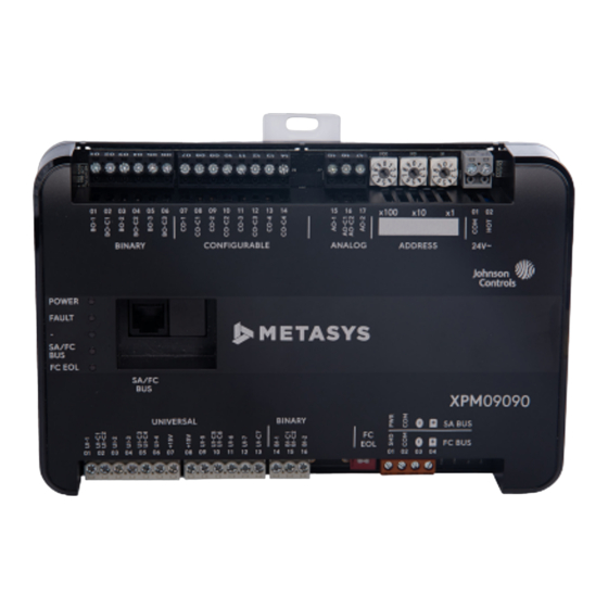
Physical features
The following figures display the physical features of XPM
expansion modules, and the accompanying table provides
a description of the physical features and a reference to
further information where required.
*241014302147B*
M4-XPM04060, M4-XPM09090, M4-XPM18000
Part No. 24-10143-02147 Rev. B
Release 12.0
2022-05-20
(For factory use only)
Advertisement

Related Manuals for Johnson Controls M4-XPM


Summary of Contents for Johnson Controls M4-XPM
- Page 1 2022-05-20 Application Canada This Class (A) digital apparatus meets all the The M4-XPM series expansion I/O modules can serve requirements of the Canadian Interference-Causing in one of two capacities depending on where they are Equipment Regulations. installed in the Metasys system. When installed on the Sensor/Actuator (SA) Bus of an equipment controller, an Cet appareil numérique de la Classe (A) respecte toutes...
- Page 2 Supply Power Terminal Block: Gray terminals; 24 VAC, Class 2. See Figure 9. Cover Lift Tab. See Removing the expansion module cover. SA/FC Bus Terminal Block: Orange terminal. See SA/FC Bus Terminal Block. End-of-Line (EOL) Switch. See Setting the End-of-Line (EOL) switch. M4-XPM Expansion Modules Installation Guide...
-
Page 3: Wall Mount Applications
Observe the following guidelines when wiring an XPM Note: expansion module: • Mounting dimensions are listed in millimeters in the above figures. • The DIN rail channel and the mounting clips are shown in an extended position. M4-XPM Expansion Modules Installation Guide... - Page 4 For detailed information about configuring and wiring an MS/TP Bus, FC bus, and SA bus, refer to the MS/TP Communications Bus Technical Bulletin (LIT-12011034). M4-XPM Expansion Modules Installation Guide...
- Page 5 SA bus that require power. Supply power terminal header SA/FC bus port Wires from Johnson Controls 24 VAC, class 2 power transformer The SA/FC bus port on the front of the expansion module is an RJ-12, 6-position modular jack that provides a...
- Page 6 Cable runs over 30 m (100 ft) may require an offset in • Run all low-voltage wiring and cables separate from the input/output software setup. high-voltage wiring. M4-XPM Expansion Modules Installation Guide...
- Page 7 Binary Output - 24 VAC Triac (External Power Source only) See Guideline C in Table 4. Connects CO-n to CO-Cn when activated. External Power Source Requirements: 24 VAC maximum output voltage 0.5 A maximum output current 40 mA minimum load current M4-XPM Expansion Modules Installation Guide...
- Page 8 0.5 A maximum output current 40 mA minimum load current BO-Cn Binary Output Common for all Binary Output terminals. Note: Each Binary Output Common terminal (BO-Cn) is isolated from all other commons, including other Binary Output Common terminals. M4-XPM Expansion Modules Installation Guide...
- Page 9 Use the following figure to estimate the maximum cable length relative to the wire size and the load current (in mA) when wiring inputs and outputs. Figure 10: Maximum wire length for low-voltage (<30 V) Inputs and Outputs by current and wire size M4-XPM Expansion Modules Installation Guide...
- Page 10 Technical Bulletin (LIT-12011034). Termination diagrams A set of Johnson Controls termination diagrams provides details for wiring inputs and outputs to the expansion modules. See the figures in this section for the applicable termination diagrams. Note: References to the analog output apply to the XPM09090 model only.
- Page 11 Table 6: Termination details Type of field Type of Input/ Termination diagrams device Output Temperature Sensor Voltage Input - External Source Voltage Input - Internal Source Voltage Input (Self-Powered) Current Input - External Source (Isolated) M4-XPM Expansion Modules Installation Guide...
- Page 12 Termination diagrams device Output Current Input - Internal Source (2- wire) Current Input - Internal Source (3 wire) Current Input - External Source (in Loop) Feedback from EPP-1000 Dry Contact UI or BI (Binary Input) M4-XPM Expansion Modules Installation Guide...
- Page 13 Type of field Type of Input/ Termination diagrams device Output 0–10 VDC Output to Actuator (External Source) 0–10 VDC Output to Actuator (Internal Source) Current Output 24 VAC Triac Output (Switch Low, External Source) Analog Output (Current) M4-XPM Expansion Modules Installation Guide...
- Page 14 Output 4–20 mA Output to Actuator 4–20 mA Output to Actuator Incremental Control to Actuator (Switch Low, Externally Sourced) 24 VAC Binary Output (Switch Low, Externally Sourced) 24 VAC Binary Output (Switch High, Externally Sourced) M4-XPM Expansion Modules Installation Guide...
- Page 15 Note: The bottom jack (J2) on the TE-700 and TE-6x00 Series Sensors is not usable as a zone bus or an SAB connection. Network Stat SA Bus with Terminals Addressable Network Stat with SA Bus Terminals (Fixed Address = 199) M4-XPM Expansion Modules Installation Guide...
-
Page 16: Setup And Adjustments
ZFR Pro wireless 4-127 To prevent any possibility of damage from an communication Note: Addresses 0-3 are accidental short, remove power from the reserved and not for use on expansion module. expansion modules. M4-XPM Expansion Modules Installation Guide... - Page 17 When an expansion module is connected to power position. with its EOL switch set to ON, the amber EOL LED on the controller cover is illuminated. M4-XPM Expansion Modules Installation Guide...
- Page 18 Observe the Status LEDs on the front of the expansion module. Table 10 provides LED status indicator information for troubleshooting the expansion module. To troubleshoot a local controller display, refer to the DIS1710 Local Controller Display Technical Bulletin (LIT-12011270) or Local Controller Display User Guide (LIT-12013762). M4-XPM Expansion Modules Installation Guide...
-
Page 19: Ordering Information And Accessories
ZFR-HPSST-0 Wireless System Survey Tool. For use with the higher power WRG1830/ZFR183x System and lower power WRZ Sensors (10mW). Refer to the ZFR-HPSST-0 Wireless Sensing System Tool Installation Guide (Part No. 24-11461-00012) for usage instructions. M4-XPM Expansion Modules Installation Guide... - Page 20 XPM expansion modules support Zigbee wireless functionality for the FC bus and for sensors with additional hardware. Device addressing for BACnet MS/TP Decimal address set using the three rotary switches; valid controller device addresses 4-127 M4-XPM Expansion Modules Installation Guide...
- Page 21 The performance specifications are nominal and conform to acceptable industry standard. For application at conditions beyond these specifications, consult the local Johnson Controls office. Johnson Controls shall not be liable for damages resulting from misapplication or misuse of its products.
-
Page 22: Repair Information
Contact information Contact your local branch office: www.johnsoncontrols.com/locations Contact Johnson Controls: www.johnsoncontrols.com/ contact-us © 2022 Johnson Controls. All rights reserved. All specifications and other information shown were current as of document revision and are subject to change without notice. www.johnsoncontrols.com...
Need help?
Do you have a question about the M4-XPM and is the answer not in the manual?
Questions and answers