Advertisement
NCM45x0-2 Series Network Control Module Installation
Instructions
MS-NCM4510-2, MS-NCM4520-2
Applications
The NCM45x0-2 Series Network Control Module is a
Metasys® supervisory controller that emulates the
NCM350/361, yet uses the same hardware platform as
the Network Automation Engine (NAE45). The
NCM45x0-2 Series is offered in two models: N2 Bus or
LON Network. In this document, Network Control Module
(NCM) refers to either model. See
North American Emissions
Compliance
United States
This equipment has been tested and found to comply
with the limits for a Class B digital device, pursuant
to Part 15 of the FCC Rules. These limits are
designed to provide reasonable protection against
harmful interference in a residential installation. This
equipment generates, uses and can radiate radio
frequency energy and, if not installed and used in
accordance with the instructions, may cause harmful
interference to radio communications. However,
there is no guarantee that interference will not occur
in a particular installation. If this equipment does
cause harmful interference to radio or television
reception, which can be determined by turning the
equipment off and on, the user is encouraged to try
to correct the interference by one or more of the
following measures:
•
Reorient or relocate the receiving antenna.
•
Increase the separation between the equipment
and receiver.
•
Connect the equipment into an outlet on a circuit
different from that to which the receiver is
connected.
•
Consult the dealer or an experienced radio/TV
technician for help.
NCM45x0-2 Series Network Control Module Installation Instructions
Canada
This Class (B) digital apparatus meets all the
requirements of the Canadian Interference-Causing
Equipment Regulations.
Cet appareil numérique de la Classe (B) respecte
toutes les exigences du Règlement sur le matériel
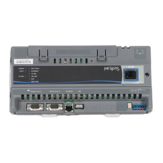
Figure
1.
brouilleur du Canada.
Installation
Follow these guidelines when installing an NCM:
•
•
•
•
Parts Included
•
•
•
Materials and Special Tools Needed
•
•
Part No. 24-10249-18, Rev. E
Supersedes January 24, 2011
Transport the NCM in the original container to
minimize vibration and shock damage to the NCM.
Verify that all the parts shipped with the NCM.
Do not drop the NCM or subject it to physical shock.
Do not open the NCM housing (except the data
protection battery compartment). The NCM has no
user-serviceable parts inside.
one NCM with removable terminal plugs
one data protection battery (installed and connected
at the factory)
one Installation Instructions sheet
three fasteners appropriate for the mounting surface
(#8 screws or M4 screws), or one 20 cm (8-in.) or
longer piece of DIN rail and appropriate hardware for
mounting the DIN rail
small straight-blade screwdriver for securing wires in
the terminal blocks
Software Release 6.0
Issued January 30, 2013
1
Advertisement
Table of Contents

Related Manuals for Johnson Controls MS-NCM4510-2


Summary of Contents for Johnson Controls MS-NCM4510-2
- Page 1 NCM45x0-2 Series Network Control Module Installation Instructions MS-NCM4510-2, MS-NCM4520-2 Part No. 24-10249-18, Rev. E Software Release 6.0 Issued January 30, 2013 Supersedes January 24, 2011 Applications Canada The NCM45x0-2 Series Network Control Module is a Metasys® supervisory controller that emulates the...
-
Page 2: Location Considerations
Figure 1: Front of NCM45x0-2 Showing Dimensions (mm/in), Physical Features, and Required Mounting Space around the NCM (mm/in) Mounting • Do not mount the NCM on surfaces that are prone to vibration or in areas where electromagnetic emissions Location Considerations can interfere with NCM communication. - Page 3 3. Drill holes in the wall at the locations marked in Step 4. Push the bottom mounting clips up to secure the NCM 2 and insert wall anchors (if necessary). on the DIN rail tracks. Figure 2: NCM Mounting Screw Hole To remove the NCM from the DIN rail, snap the bottom Dimensions and Mounting Area Requirements DIN clips to the outward extended position, and carefully...
- Page 4 NCM100 or NCM200 that is installed in a NCM45x0-2 Network Control Module Commissioning baseframe enclosure Guide (LIT-12011176) for details. NCM that is an Attached Resource Computer • While the NCM45x0-2 is restarting, the LEDs on the Network (ARCNET®) node. A Metasys Ethernet unit are not used to indicate its network address or Router may be required if the current network act as diagnostic indicators of a particular error...
-
Page 5: Ethernet Port
Mount the NCM securely before wiring the NCM. See the Refer to the NCM45x0-2 Network Control Module Mounting section. Commissioning Guide (LIT-12011176) for information about these different types of direct and dial-up Follow these guidelines when wiring an NCM: connections to the NCM. •... - Page 6 Figure 6: Network Terminal Block and Wiring Figure 7: 24 VAC Supply Power Wiring Connections Note: Power supply wire colors may be different on transformers not manufactured by Johnson 4. If a dial application is required, connect an external Controls®. Follow the transformer manufacturer’s modem to the RS232C port you wish to use.
-
Page 7: Setup And Adjustments
Table 2: Guidelines for L Network Bus Topology ORKS Cable Type Maximum Segment Length with FTT10 Maximum Segment Length with FTT10 and/or LPT10 Devices Only Devices Level IV 22 AWG 1,400 m (4,600 ft) 1,150 m (3,770 ft) JY (St.) Y 2 x 2 x 0.8 900 m (2,950 ft) 750 m (2,460 ft) 1 For the bus topology, the maximum length stub cable is 3 m (10 ft), and the stub lengths must be calculated into the overall... -
Page 8: Troubleshooting
The data protection battery slowly loses charge when 24 Important: Do not disconnect the battery while the unit VAC power is removed from the NCM. If the battery is shutting down, or the data being saved completely loses charge, the NCM real-time clock stops. may be corrupted. -
Page 9: Repair Information
Up to 127 devices ORKS ORKS are supported on the L port. ORKS MS-NCM4510-2G Buy American equivalent to MS-NCM4510-2 MS-NCM4520-2G Buy American equivalent to MS-NCM4520-2 MS-NCM4510-702 Repair for MS-NCM4510-2 MS-NCM4520-702 Repair for MS-NCM4520-2 NCM45x0-2 Series Network Control Module Installation Instructions... -
Page 10: Technical Specifications
Table 8: NCM45x0-2 Accessories Ordering Information Product Code Number Description MS-BAT1020-0 Replacement data protection battery: Rechargeable NiMH 3.6 VDC, 500 mAh battery with a typical life of 5 to 7 years at 21°C (70°F) (Higher operating temperatures reduce battery life.) Y65T31-0 Power transformer family (Class 2, 24 VAC, 40 VA maximum output), no enclosure... - Page 11 The performance specifications are nominal and conform to acceptable industry standard. For application at conditions beyond the specifications, consult the local Johnson Controls office. Johnson Controls, Inc. shall not be liable for damages resulting from misapplication or misuse of its products.
Need help?
Do you have a question about the MS-NCM4510-2 and is the answer not in the manual?
Questions and answers