Advertisement
Quick Links
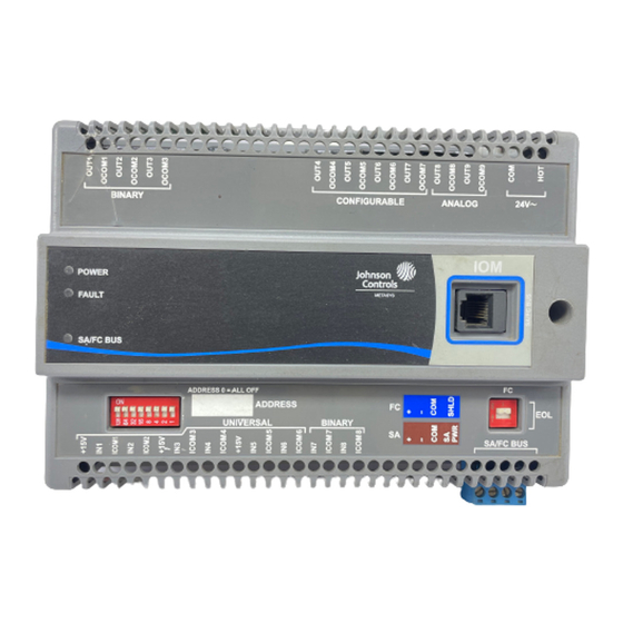
IOU4710 Input/Output Module Installation Instructions
MS-IOU4710-0U
Application
The IOU47 field controller is part of the Metasys® system
Field Equipment Controller family. This controller expands
the number of points connected to a Network Automation
Engine (NAE), Network Control Engine (NCE), Field
Equipment Controller (FEC), or Advanced Application
Field Equipment Controller (FAC) to monitor and control
a wide variety of HVAC equipment.
The IOU controller operates on an RS-485 BACnet®
MS/TP Bus as BACnet Application Specific Controllers
(B-ASCs) and integrate into Johnson Controls® and
third-party BACnet systems.
Note: With CCT Release 10.3 and Release Module (RM)
10.2, a new capability allows VMAs, FECs, and
FACs to communicate by using either the BACnet
or the N2 field bus networking protocol. The I/O
can be connected through the SA bus to a host
controller that is using either the BACnet or the
N2 protocol. Only the BACnet protocol is
supported when the I/O is connected directly to
the trunk using the FC bus.
Important: The MS-IOU4710-0U model is used in
Metasys Release 8.1 smoke control
applications and is UL 864 UUKL/UUKLC
10th Edition Smoke Control Listed. You
must refer to the Metasys® System UL 864
10th Edition UUKL/ORD-C100-13 UUKLC
Smoke Control System Technical Bulletin
(LIT-12012487) for detailed requirements
and procedures for installing,
commissioning, and operating UL 864
UUKL/UUKLC Listed Metasys system
devices. The UL 864 UUKL/UUKLC listing
for Smoke Control Equipment is voided if
(1) you do not use the required software
tools at the required versions; or (2) you do
not meet the requirements or do not follow
the procedures as documented in the
Metasys® System UL 864 10th Edition
UUKL/ORD-C100-13 UUKLC Smoke
Control System Technical Bulletin
(LIT-12012487).
IOU4710 Input/Output Module Installation Instructions
Part No. 24-10144-254, Rev. A
North American Emissions
Compliance
Canada
This Class (A) digital apparatus meets all the
requirements of the Canadian Interference-Causing
Equipment Regulations.
Cet appareil numérique de la Classe (A) respecte toutes
les exigences du Règlement sur le matériel brouilleur
du Canada.
United States
This equipment has been tested and found to comply
with the limits for a Class A digital device pursuant to
Part 15 of the FCC Rules. These limits are designed to
provide reasonable protection against harmful
interference when this equipment is operated in a
commercial environment. This equipment generates,
uses, and can radiate radio frequency energy and, if not
installed and used in accordance with the instruction
manual, may cause harmful interference to radio
communications. Operation of this equipment in a
residential area may cause harmful interference, in which
case the users will be required to correct the interference
at their own expense.
Installation
Observe these guidelines when installing a controller:
•
Transport the controller in the original container to
minimize vibration and shock damage.
•
Verify that all parts shipped with the controller.
•
Do not drop the controller or subject it to physical
shock.
Parts Included
•
one controller with removable terminal blocks (Power
and SA/FC bus are removable)
•
one installation instructions sheet
Software Release 8.1
Issued March 2018
1
Advertisement

Related Manuals for Johnson Controls MS-IOU4710-0U


Summary of Contents for Johnson Controls MS-IOU4710-0U
- Page 1 FC bus. uses, and can radiate radio frequency energy and, if not installed and used in accordance with the instruction Important: The MS-IOU4710-0U model is used in manual, may cause harmful interference to radio Metasys Release 8.1 smoke control communications.
- Page 2 Figure 1: Controller Mounting Positions Materials and Special Tools Needed • three fasteners appropriate for the mounting surface (M4 screws or #8 screws) • one 20 cm (8 in.) or longer piece of 35 mm DIN rail and appropriate hardware for DIN rail mount (only) •...
- Page 3 1. Place the hinge tabs (cover) onto the top of the hinge Important: Do not overtighten the mounting screws. slots (base). Overtightening the screws may damage Do not fully insert the tabs into the slots. If the tabs the mounting clips. are fully inserted into the slots, the cover hinge may Figure 2: Back of Controller Showing Extended not allow the cover to close.
- Page 4 Figure 4: IOU4710 Physical Features (Labeled IOM) Wiring Observe the following guidelines when wiring a controller: Risk of Property Damage: Do not apply power to the system before checking all wiring connections. Short circuited or improperly connected wires may result in permanent damage to the equipment.
- Page 5 Important: Electrostatic discharge can damage controller components. Use proper electrostatic discharge precautions during When connecting the IOU to an SA bus, wire the bus installation, setup, and servicing to avoid terminal block plugs on the controller and other SA bus damaging the controller.
- Page 6 Figure 7: Pin Number Assignments for Sensor, SA Figure 8: 24 VAC Supply Power Terminal Block Wiring Bus and FC Bus Ports on Controllers Supply Power Terminal Block The 24 VAC supply power terminal block is a gray, removable, 3-terminal plug that fits into a board-mounted Important: Connect 24 VAC supply power to the jack on the top right of the controller.
- Page 7 Termination Details A set of Johnson Controls® termination diagrams provides details for wiring inputs and outputs to the controllers. See the figures in this section for the applicable termination diagrams. Table 1: Termination Details Type of Field Device Type of...
- Page 8 Table 1: Termination Details Type of Field Device Type of Termination Diagrams Input/Output Current Input - Internal Source (3 wire) Current Input - External Source (in Loop) Feedback from EPP-1000 Dry Contact (Binary Input) UI or BI 0–10 VDC Output to Actuator CO or AO (External Source) 0–10 VDC Output to Actuator...
- Page 9 Table 1: Termination Details Type of Field Device Type of Termination Diagrams Input/Output 4–20 mA Output to Actuator CO or AO 4–20 mA Output to Actuator CO or AO Voltage (Analog Output) Analog Output (Current) 24 VAC Triac Output (Switch CO or AO Low, External Source) Incremental Control to...
- Page 10 Table 1: Termination Details Type of Field Device Type of Termination Diagrams Input/Output Incremental Control to CO or AO Actuator (Switch High, Externally Sourced) Incremental Control to Actuator (Switch Low, Externally Sourced) 24 VAC Binary Output (Switch Low, Externally Sourced) 24 VAC Binary Output (Switch High, Externally Sourced) Incremental Control to...
- Page 11 Table 1: Termination Details Type of Field Device Type of Termination Diagrams Input/Output Network Stat with Phone Jack SA Bus (Fixed Address = 199) Network Stat with Terminals SA Bus Addressable Network Stat with Terminals SA Bus (Fixed Address = 199) Terminal Wiring Guidelines, In addition to the wiring guidelines in Table...
- Page 12 Table Internal 12 V. 15k ohm pull up Qualified Sensors: 0-2k ohm potentiometer, RTD (1k Nickel [Johnson Controls® sensor], 1k Platinum, and A99B Silicon Temperature Sensor) Negative Temperature Coefficient (NTC) Sensor (10k Type L, 10k JCI Type II, 2.252k Type...
- Page 13 Table 2: IOU47 Terminal Blocks, Functions, Ratings, Requirements, and Cables Terminal Block Terminal Function, Ratings, Requirements Determine Wire Size and Label Label Maximum Cable Length ANALOG OUTn Analog Output - Voltage Mode (0–10 VDC) See Guideline C in Table (Outputs) 10 VDC maximum output voltage 10 mA maximum output current Required an external load of 1,000 ohm or more.
- Page 14 Table 2: IOU47 Terminal Blocks, Functions, Ratings, Requirements, and Cables Terminal Block Terminal Function, Ratings, Requirements Determine Wire Size and Label Label Maximum Cable Length CONFIGURABLE OUTn Analog Output - Voltage Mode (0–10 VDC) See Guideline A in Table (Outputs) 10 VDC maximum output voltage 10 mA maximum output current Required an external load of 1,000 ohm or more.
- Page 15 Cable and Wire Length Guidelines Table 3 defines cable length guidelines for the various wire sizes that may be used for wiring low-voltage (<30 V) input and outputs. Table 3: Cable Length Guidelines for Recommended Wire Sizes for Low-Voltage (<30 V) Inputs and Outputs Guideline Wire Size/Gauge and Type Maximum Cable...
- Page 16 In addition to the guidelines in Table 4, observe these SA/FC Bus and Supply Power guidelines when wiring an SA or FC bus and the 24 VAC Wiring Guidelines supply power: Table 4 provides information about the functions, ratings, • Run all low-voltage wiring and cables separate from and requirements for the communication bus and supply high-voltage wiring.
-
Page 17: Setup And Adjustments
64, 32, 16, 8, 4, 2, and 1 (Figure 10). Switches 64 through addresses for Johnson Controls MS/TP 1 are device address switches. Switch 128 is a mode communications bus applications. switch that enables a controller to operate on a ZFR/ZFR Pro Series Wireless Field Bus. - Page 18 Setting the End-of-Line (EOL) Switch Important: Do not connect an external power source to a binary output (BO) when the BO power Each controller has an EOL switch, which, when set to source jumper is in the internal power (INT) ON, sets the controller as a terminating device on the position.
-
Page 19: Replacing The Fuse
Tool Help (LIT-12011147) for detailed information on commissioning controllers. Repair Information The MS-IOU4710-0U model is UL 864 10th Edition UUKL/ORD-C100-13 UUKLC listed for smoke control. If a controller fails to operate within its specifications, contact the Johnson Controls Repair Center in Louisville, Kentucky, at 1-502-671-7312. -
Page 20: Technical Specifications
Technical Specifications Table 8: IOU4710-0U Technical Specifications Product Code Number MS-IOU4710-0U Input/Output Module, model listed for Smoke Control, consisting Supply Voltage 24 VAC (nominal, 20 VAC minimum/30 VAC maximum), 50/60 Hz, power supply Class 2 (North America) Power Consumption... - Page 21 The performance specifications are nominal and conform to acceptable industry standard. For application at conditions beyond these specifications, consult the local Johnson Controls® office. Johnson Controls shall not be liable for damages resulting from misapplication or misuse of its products.
- Page 22 Building Technologies & Solutions 507 E. Michigan Street, Milwaukee, WI 53202 Johnson Controls® is a registered trademark of Johnson Controls. All other marks herein are the marks of their respective owners.© 2018 Johnson Controls Published in U.S.A. www.johnsoncontrols.com IOU4710 Input/Output Module Installation Instructions...
Need help?
Do you have a question about the MS-IOU4710-0U and is the answer not in the manual?
Questions and answers