Table of Contents
Advertisement
Quick Links
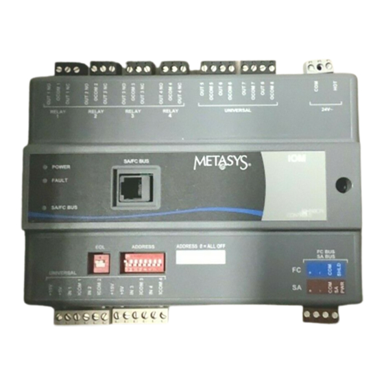
IOM2710 and IOM3710 Input/Output Modules
Installation Instructions
MS-IOM2710-0U, MS-IOM3710-0U
Applications
The Input/Output Module (IOM) 2710 and IOM3710 are
members of the Metasys® system Field Equipment
Controller (FEC) family. The IOM controller provides
increased capacity to larger FEC applications when
used on the Sensor-Actuator (SA) Bus. The IOM
controller can also be used on the Field Controller (FC)
Bus to connect additional I/O points to the system.
IMPORTANT: The MS-IOM2710-0U and MS-
IOM3710-0U models are used in Metasys Release
8.1 smoke control applications and are UL 864
UUKL/UUKLC 10th Edition Smoke Control Listed.
You must refer to the Metasys® System UL 864
10th Edition UUKL/ORD-C100-13 UUKLC Smoke
Control System (LIT-12012487) for detailed
requirements and procedures for installing,
commissioning, and operating UL 864 UUKL/
UUKLC Listed Metasys system devices. The UL 864
UUKL/UUKLC listing for Smoke Control Equipment
is voided if (1) you do not use the required software
tools at the required versions; or (2) you do not meet
the requirements or do not follow the procedures as
documented in the Metasys® System UL 864 10th
Edition UUKL/ORD-C100-13 UUKLC Smoke
Control System (LIT-12012487).
North American Emissions Compliance
United States
This equipment has been tested and found to
comply with the limits for a Class A digital device
pursuant to Part 15 of the FCC Rules. These limits
are designed to provide reasonable protection
against harmful interference when this equipment is
operated in a commercial environment. This
equipment generates, uses, and can radiate radio
frequency energy and, if not installed and used in
accordance with the instruction manual, may cause
harmful interference to radio communications.
Operation of this equipment in a residential area is
likely to cause harmful interference, in which case
the user will be required to correct the interference
at his/her own expense.
Canada
This Class (A) digital apparatus meets all the
requirements of the Canadian Interference-Causing
Equipment Regulations.
Cet appareil numérique de la Classe (A) respecte
toutes les exigences du Règlement sur le matériel
brouilleur du Canada.
Installation
Observe the following guidelines when installing the
IOM controller:
•
Transport the IOM controller in the original
container to minimize vibration and shock damage
to the IOM.
•
Do not drop the IOM controller or subject it to
physical shock.
Materials and Special Tools Needed
You need either of the following items to install the IOM
controller:
•
three fasteners appropriate for the mounting
surface (#8 screws or M4 screws)
•
one 20.3 cm (8 in.) or longer piece of DIN rail and
appropriate hardware for mounting the DIN rail
Mounting
Follow these guidelines when mounting an IOM
controller:
•
Ensure that the mounting surface can support the
IOM controller and any user-supplied enclosure.
•
Mount the IOM controller in the proper orientation.
See the Wall Mount Applications and DIN Rail
Mount Applications sections.
•
Mount the IOM controller on an even surface
whenever possible.
•
Use shims or washers to mount the unit securely
on the mounting surface.
•
Mount the IOM controller in areas free of corrosive
vapors and observe the environmental limitations
listed in the Technical Specifications section.
IOM2710 and IOM3710 Input/Output Modules Installation Instructions
(barcode for factory use only)
Part No. 24-10144-262, Rev. A
Issued March 2018
Release 8.1
1
Advertisement
Table of Contents

Related Manuals for Johnson Controls MS-IOM2710-0U


Summary of Contents for Johnson Controls MS-IOM2710-0U
- Page 1 Règlement sur le matériel Bus to connect additional I/O points to the system. brouilleur du Canada. IMPORTANT: The MS-IOM2710-0U and MS- Installation IOM3710-0U models are used in Metasys Release Observe the following guidelines when installing the 8.1 smoke control applications and are UL 864...
-
Page 2: Wall Mount Applications
• Do not mount the IOM controller on surfaces that On panel or enclosure mount applications, observe are prone to vibration, such as duct work, or in these guidelines: areas where electromagnetic emissions from other • Do not install the IOM controller in an airtight devices or wiring can interfere with IOM controller enclosure. - Page 3 To remove the IOM controller from the DIN rail, snap Figure 2: IOM27/37 Controller Mounting Features, the bottom DIN clips to the outboard position and mm (in.) carefully lift the IOM controller off the DIN rail. 1-7/8 Figure 4: Required Orientation for DIN Rail Mount Applications 3-1/2 3-1/2...
- Page 4 Note: The SA/FC Bus Port (RJ-12 6-position Figure 5: FC Bus Terminal Block Wiring modular connector) provides 15 VDC on one of its pins, which is used to power the MS-BTCVT. Note: If the IOM controller is at one end of the SA Bus daisy chain, set the End-of-Line (EOL) switch to ON.
- Page 5 Table 1: IOM2710 and IOM3710 Controller Wiring List (Part 1 of 2) Terminal Terminal Function and Electrical Ratings/Requirements Wiring Requirements Labels (See Table 2 for A, B, or C.) Block Universal IN +5 V Sources 5 VDC power for active devices Same as IN 60 mA total current +15 V...
- Page 6 Table 1: IOM2710 and IOM3710 Controller Wiring List (Part 2 of 2) Terminal Terminal Function and Electrical Ratings/Requirements Wiring Requirements Labels (See Table 2 for A, B, or C.) Block Relay OUT NO n Normally Open Contact Output Connects OCOM to OUT NO when activated. Control 240 VAC maximum voltage 1/3 hp 125 VAC, 1/2 hp 250 VAC...
-
Page 7: Setup And Adjustments
Table 3 shows and describes the valid FC Bus and SA Bus devices addresses for FECs and IOMs on The IOM controller can reside on either the FC Bus or Johnson Controls® MS/TP communications bus the SA Bus. When you set the address, you are setting applications. -
Page 8: Troubleshooting
Use Table to order accessories for the IOM controller. are UL 864 10th Edition UUKL/ORD-C100-13 UUKLC listed for smoke control. If the device fails to operate within its specifications, contact the Johnson Controls Repair Center in Louisville, Kentucky, at 1-502-671- 7312. -
Page 9: Technical Specifications
The performance specifications are nominal and conform to acceptable industry standard. For application at conditions beyond these specifications, consult the local Johnson Controls office. Johnson Controls, Inc. shall not be liable for damages resulting from misapplication or misuse of its products. - Page 10 507 E. Michigan Street, Milwaukee, WI 53202 Metasys® and Johnson Controls® are registered trademarks of Johnson Controls. All other marks herein are the marks of their respective owners. © 2018 Johnson Controls. IOM2710 and IOM3710 Input/Output Modules Installation Instructions Published in U.S.A.
Need help?
Do you have a question about the MS-IOM2710-0U and is the answer not in the manual?
Questions and answers