
Related Manuals for Rice Lake EL232 XPCD


Summary of Contents for Rice Lake EL232 XPCD
- Page 1 EL232 XPCD Explosion Proof Remote Display Installation Manual To be the best by every measure 16942...
-
Page 3: Table Of Contents
3.3 Configuration of the EL232 XPCD........ - Page 4 ES232 XPCD Installation Manual...
-
Page 5: About This Manual
This EL232 has been modified for use in a hazardous electrical environment. This manual provides information on installation of the EL232 XPCD. The installer should be familiar with the National Electrical Code and RP 12.6 ( Recommended Practice ) requirements for installation of equipment in hazardous areas (NEC Article 504, Intrinsically Safe Systems ) published through the Instrument Society of America. - Page 6 The push buttons, rotary switches and sealing fittings are all attached to the enclosure via drilled and tapped holes in the enclosure. Just as with the flange, all threaded operators and fittings carefully control the flame path. EL232 XPCD Installation Manual...
- Page 7 Enlarged view below Explosion Propagation of gas due to pressure from an internal explosion The distance from the boundary of Cooling from the inside of the enclosure to the expansion of gas gasket is known as the Flame Path. (Boyle’s Gas Law) This distance must be at least 1"...
- Page 8 EL232 XPCD Installation Manual...
-
Page 9: Introduction
Introduction The EL232 XPCD is a high performance serial remote data display. It receives serial ASCII data (20 mA current loop or RS-232), and displays weight data on a 8" LED display. Five LED status indicators are provided for Lbs, Kg, Gross, Net, and no signal. -
Page 10: Front Panel Annunciators
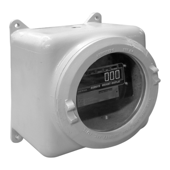
Front Panel Annunciators Figure 1-1 illustrates the EL232 XPCD front panel which include six LED display digits and five LED annunciators. L B S K G S G R O S S N E T NO SIGNAL REMOTE WEIGHT DISPLAY MADE IN U.S.A. -
Page 11: Installation And Wiring
Glass Face The glass face on the EL232 XPCD may look indestructible but it is not. If damaged in any way, the entire unit must be completely turned off at the source until it is replaced. The enclosure must be protected from blows and scrapes from passing equipment, falling objects, thick glues or resins, certain acids which eat aluminum, and other hazards which can break or damage the enclosure. -
Page 12: Sealoff Fittings
Sealoff Fittings The utmost care must be taken to completely seal the inside of the remote display off from the outside world. To do this all wiring into and out of the enclosure must be in conduit using sealoff fittings between the remote display and the conduit. -
Page 13: Cabling And Conduit Runs
Cabling and Conduit Runs 2.3.1 Cabling There are two types of cables that pass through a sealoff fitting, single conductor and multi conductor. Single Conductor Cabling Single conductor cables are typically redundant ground wires (used with resistive intrinsic safety barrier). Due to the nature of the method by which insulation is applied to wire, a single conductor wire (single or multi strand) can be considered gas tight. -
Page 14: Conduit Runs
2.3.2 Conduit Runs Conduit can be run either vertically or horizontally. But either way the conduit must be sealed properly to maintain the explosion proof integrity of the unit. The following paragraphs explain the proper way to install a conduit run and the sealing fittings. Horizontal Conduit Runs ®... -
Page 15: Ac Power Wiring
AC Power Wiring Electrical connections made in an explosion proof installation are made through rigid steel conduit through threaded openings in the back or sides of the enclosure and must comply with the National Electrical Code for installation of equipment in hazardous areas (NEC Article 504, Intrinsically Safe Systems ). -
Page 16: Indicator Setup
(or if you have a custom program). Note: Set up the EL232 XPCD on the bench with the indicator you intend to use before taking it to the installation site. Brand Model... -
Page 17: Condec Data Format
Use when all else fails. Table 3-1. Indicator Setup Parameters (Continued) Any device that has a programmable ASCII output can be used with the EL232 XPCD. Set the device to emulate any of the following: 3.1.1 Condec Data Format Figure 3-1 shows the Condec UMC series continuous output data format. -
Page 18: Analogic Data Format
3.1.3 Analogic Data Format Figure 3-3 shows the Analogic continuous output data format. <STX> <nnnnnnnnn> <ttttttttt> <SP> <S> <UNIT> <SP> <TERM> Space Space <CR> or STX (02h) character character <LF> or <CR> <LF> Net Weight: 9 characters, 7 Status <S> is the sum of: 0 = kilogram active weight digits, no leading 1 = gram... -
Page 19: 20 Ma Active Current Loop Input
Figure 3-6. 20 mA Active Current Loop Input Hookup The 20 mA receiver in the EL232 XPCD is a HP-4200 and requires current swings of less than 4 mA as a mark and greater than 12 mA for a space. The output of the HP-4200 is a TTL signal which appears at pin #7 of the chip. -
Page 20: 20 Ma Passive Current Loop Input
5 VDC, it can normally only drive two drops. If the same loop were powered by 24 VDC, it could power about 11 remote displays. The EL232 XPCD can supply power to a passive current loop. This voltage supplies about 8 VDC for use in the loop. -
Page 21: Configuration Of The El232 Xpcd
Configuration of the EL232 XPCD To configure the EL232 XPCD, you must know the following: • Baud rate • Indicator type • Data format - RS232 or 20 mA current loop Once this information is known, it is entered through SW1, the eight-position DIP switch on the upper left hand... -
Page 22: Loss Of Signal Display
Serial Data Output The EL232 XPCD comes standard with an active 20 Indicator mA current loop transmitter which echoes the serial Indicator Type SW1-3 SW1-4 SW1-5 SW1-6 data received by the EL232 XPCD. This data is echoed as a 20 mA loop regardless of whether the Condec input source was RS232 or current loop. -
Page 23: El232 Xpcd Operation
Once power is applied, the EL232 XPCD enters the power on clear mode. All status switches are read at this time and the unit is configured for baud rate, indicator type, and input signal type. The EL232 XPCD display goes through a power up sequence which can provide valuable information about the operating condition and setup of the unit. -
Page 24: Receiving Data For The First Time
Receiving Data for the First Time After the power up sequence, the EL232 XPCD synchronizes with the incoming serial data line and looks for data to receive. If no readable data is received within a few seconds, the NO SIG LED... -
Page 25: Appendix
Use an oscilloscope, printer, logic probe, or voltmeter to verify that the meter is sending continuous data. Use a logic probe to check the signal on the EL232 XPCD CPU board to see if data is actually being received. Connect the probe as shown below. -
Page 26: Specifications
Approximately 25 lb (11.3 kg) Baud Rate: 1200, 2400, 4800, and 9600 Interfaces: 20 mA and RS232 standard. The EL232 XPCD can communicate, as shipped, with twelve of the most common scale indicator families currently available. Please consult factory for model numbers and interface requirements. -
Page 27: El232 Xpcd Limited Warranty
EL232 XPCD Limited Warranty Rice Lake Weighing Systems (RLWS) warrants that all RLWS equipment and systems properly installed by a Distributor or Original Equipment Manufacturer (OEM) will operate per written specifications as confirmed by the Distributor/OEM and accepted by RLWS. All systems and components are warranted against defects in materials and workmanship for one year. - Page 30 230 W. Coleman St. • Rice Lake, WI 54868 • USA U.S. 800-472-6703 • Canada/Mexico 800-321-6703 International 715-234-9171 www.ricelake.com mobile: m.ricelake.com © 2011 Rice Lake Weighing Systems PN 16942 06/11...
Need help?
Do you have a question about the EL232 XPCD and is the answer not in the manual?
Questions and answers