Table of Contents
Advertisement
Quick Links
Installation Instructions
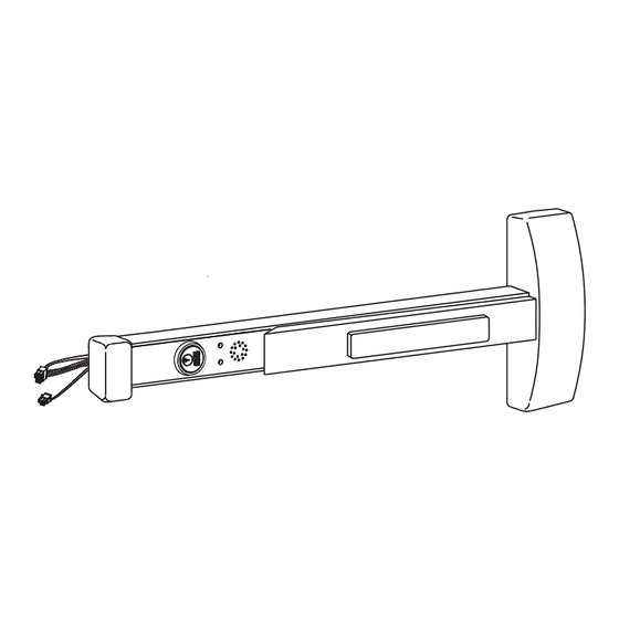
Delayed Egress 57-80 Series
Exit Device
WARNING
This product can expose you to
lead which is known to the state of
California to cause cancer and birth
defects or other reproductive harm.
For more information go to www.
P65warnings.ca.gov.
1-800-727-5477 • www.sargentlock.com
Copyright © 2005, 2007, 2023, SARGENT Manufacturing Company. All rights reserved. Reproduction in whole or in part without the express
written permission of SARGENT Manufacturing Company is prohibited. Patent pending and/or patent www.assaabloydss.com/patents.
WARNING
Attention Installer: Improper
installation may result in dam-
age to the product and void the
factory warranty.
A7743F 1/23
Advertisement
Table of Contents

Related Manuals for Assa Abloy SARGENT Delayed Egress 57-80 Series


Summary of Contents for Assa Abloy SARGENT Delayed Egress 57-80 Series
- Page 1 Installation Instructions Delayed Egress 57-80 Series Exit Device WARNING WARNING This product can expose you to Attention Installer: Improper lead which is known to the state of installation may result in dam- California to cause cancer and birth age to the product and void the defects or other reproductive harm.
-
Page 2: Table Of Contents
Delayed Egress 57-80 Series Exit Device Installation Instructions Table of Contents Warning ..................3 General Description . -
Page 3: Warning
Delayed Egress 57-80 Series Exit Device Installation Instructions Warning FCC: This equipment has been tested and found to comply with the limits for a Class B digital device, pursuant to Part 15 of the FCC Rules. These limits are designed to provide reasonable protection against harmful interference in a residential installation. -
Page 4: General Description
Delayed Egress 57-80 Series Exit Device Installation Instructions General Description The SARGENT 57-Delayed Egress Exit Device is designed to work with an external electromagnetic lock in areas that require a delayed egress which alarms at the door when any attempt is made to violate the door. The 57- device can be tied into a fi re alarm system. -
Page 5: Component Installation
Delayed Egress 57-80 Series Exit Device Installation Instructions Component Installation 1. Determine locations of components at the door. 2. Mount all hardware and peripheral equipment according to manufacturer’s instructions. Note: For exit device mechanical installation, refer to mechanical instruction sheets and templates included with product. •... - Page 6 Delayed Egress 57-80 Series Exit Device Installation Instructions Component Installation (Continued) Verify hand and bevel of door. Exit devices are always reverse bevel and are mounted on the inside of the door. Left Hand Right Hand Reverse Bevel Reverse Bevel Hinges Left Hinges Right Open Outward...
- Page 7 With new applications, a raceway harness with 8- and 4-pin connectors will be pre-installed inside the door by ASSA ABLOY door manufacturer when specifi ed during the ordering process. Raceway harness kits are also available for retrofi t applications. (For retrofi t applications, refer to retrofi t instructions.) •...
-
Page 8: Cylinder Installation
Delayed Egress 57-80 Series Exit Device Installation Instructions Cylinder Installation 1. Prepare door according to template(s) and instructions supplied with exit device. 2. Verify cylinder (size varies; consult factory) is installed in rail insert with collar prior to installing exit device on door. -
Page 9: Factory Default Settings
Delayed Egress 57-80 Series Exit Device Installation Instructions Factory Default Settings After verifying the factory default settings for the DIP switch, install the insert assembly to the rail assembly. If default feature settings need to be changed, carefully slide the insert assembly from the rail assembly to make the proper DIP switch adjustments. -
Page 10: Dip Switch Settings
Delayed Egress 57-80 Series Exit Device Installation Instructions DIP Switch Settings S2-1 Nuisance Delay (Field selectable 0 or 1 second) S2-1 A one second nuisance delay can be enabled by setting Dip Switch (S2-1) to the “On” position. When nuisance delay is enabled, the unit will require the push bar to be depressed for more than one second in order to trigger an irreversible alarm condition. -
Page 11: Wiring
1. With new applications, a raceway harness with 8 & 4-pin connectors will be pre-installed inside the door by ASSA ABLOY door manufacturer when specifi ed during the ordering process. Raceway harness kits are also available for retrofi t applications. (For retrofi t applications, refer to retrofi t instructions) 2. - Page 12 Delayed Egress 57-80 Series Exit Device Installation Instructions Wiring (Continued) The following are the input and output connector designations. Harness Connector Circuit Board Input/ Harness Function PIN No.* PIN No. Output Wire Color J1-1 input +24VDC power J1-2 input Black -Return N.O.
- Page 13 Delayed Egress 57-80 Series Exit Device Installation Instructions Wiring (Continued) Harness Connector I/O Circuit Function PIN No.* Board PIN No. 24VDC Power Supply Input (+) This input may be tied to the normally closed contact of a building’s fi re alarm system. J1-1 If the fi...
-
Page 14: Exit Device Plug-In Connector Installation
Delayed Egress 57-80 Series Exit Device Installation Instructions Exit Device Plug-in Connector Installation Note: No fi eld rail cutoff allowed. Exit device must be ordered for specifi c door width. 1. Mount exit device per instruction sheet provided. To insure trouble free operation, check that the push rail can be fully depressed. On vertical rod exit devices, check that the latch bolts do not go into hold back position until the push rail is fully depressed. -
Page 15: Sample Wiring Instructions
Delayed Egress 57-80 Series Exit Device Installation Instructions Sample Wiring Instructions Basic 57- Delayed Egress with Fire Alarm and Remote Reset During a fi re alarm condition, the fi re alarm contact opens which de-energizes the rail magnet and allows immediate egress. -
Page 16: 57- Exit Device With Inside Keypad, Fire Alarm, Door Status And Remote Horn
Delayed Egress 57-80 Series Exit Device Installation Instructions Sample Wiring Instructions 57- Exit Device with inside Keypad, Fire Alarm, Door Status and Remote Horn A valid code entry at the 4291 (Inside) keypad shunts the 57- exit device and allows egress for a time period programmable at the keypad. -
Page 17: 57- Exit Device With Fire Alarm, Keypads And Fail Safe Et
Delayed Egress 57-80 Series Exit Device Installation Instructions Sample Wiring Instructions 57- Exit Device with Fire Alarm, Keypads and Fail Safe ET During a fi re alarm condition, the contact opens which de-energizes the rail electromagnet and allows immediate egress. A valid code entry at the 4291 (Inside) keypad shunts the 57- exit device and allows egress for a time period programmable at this keypad. -
Page 18: Operating Instructions
Delayed Egress 57-80 Series Exit Device Installation Instructions Operating Instructions Power Up Sequence 1. Both insert LEDs illuminate “red” for 2 seconds while concurrently sounding buzzer for 500ms. 2. Both insert LEDs illuminate “green” for 2 seconds (no buzzer). 3. The (4) diagnostic LEDS on bottom of module illuminate for 2 seconds. 4. - Page 19 Delayed Egress 57-80 Series Exit Device Installation Instructions Operating Instructions (Continued) Modes of Operation (Continued) Maintained Egress Mode Maintained Egress Mode 1. Rotate key fully clockwise (one click) and return key to center position (remove key). 2. Red (default) or Green LED will illuminate. See Dip Switch Settings section 6 for LED color settings.
- Page 20 Delayed Egress 57-80 Series Exit Device Installation Instructions Operating Instructions Modes of Operation (Continued) Unit Tied Into A Fire Alarm System – Optional for Non-Labeled Devices 1. In case of a fi re/emergency, the rail assembly will release the external electromagnet instantaneously, voiding the 15 second delay, allowing immediate egress and continuous immediate egress.
-
Page 21: Troubleshooting
Delayed Egress 57-80 Series Exit Device Installation Instructions Troubleshooting Diagnostic and Insert LEDs The tables below are provided to assist in the installation and troubleshooting of the 57- exit device. Insert LEDs Yellow Orange Green Important: Always remove power to the rail before disconnecting or reconnecting connectors at the 57- PCB module assembly. -
Page 22: Rim, Mortise And Vertical Rod Exit Devices
Delayed Egress 57-80 Series Exit Device Installation Instructions Troubleshooting (Continued) Rim, Mortise and Vertical Rod Exit Devices When jumper is missing or in wrong position, the Yellow Diagnostic LED turns ON. To locate (J5) jumper, remove the Insert Assembly and Insert Assembly Plate. Default factory setting for 1 2 3 57- shown... -
Page 23: Symptom/Failure
Delayed Egress 57-80 Series Exit Device Installation Instructions Troubleshooting (Continued) Symptom/Failure *Refer to Diagnostic LED Table/Description and Minimum Requirements to Arm Rail sections. 1. Rail won’t arm. Armed LED won’t turn ON. Horn sounds immediately or after a delay. When trying to arm, the rail goes into alarm immediately after momentary egress times out or after a short delay after the momentary egress times out. - Page 24 Copyright © 2005, 2007, 2023, SARGENT Manufacturing Company. All rights reserved. Reproduction in whole or in part without the express written permission of SARGENT Manufacturing Company is A7743F 1/23 prohibited. Patent pending and/or patent www.assaabloydss.com/patents.
Need help?
Do you have a question about the SARGENT Delayed Egress 57-80 Series and is the answer not in the manual?
Questions and answers