Advertisement
Quick Links
Advertisement

Related Manuals for Assa Abloy SARGENT Profile v.G1.5/LK


Summary of Contents for Assa Abloy SARGENT Profile v.G1.5/LK
- Page 1 Profile & LK Mortise Lock Installation Instructions A7855C 02/14 Copyright 2014, Sargent Manufacturing Company, an ASSA ABLOY Group company. All rights reserved. Reproduction in whole or in part without the express written permission of Sargent Manufacturing Company is prohibited.
-
Page 2: Table Of Contents
Table of Contents Warning ...................2 General Description ..............3 Specifications ................3 Features ...................3 Parts Breakdown ..............4 Installation Instructions ............6 RF Technology Lock ...............15 Hardwire Wiring Options ............16 Operational Check ..............21 Warning Changes or modifications to this unit not expressly approved by the party responsible for compliance could void the user’s authority to operate the equipment. -
Page 3: General Description
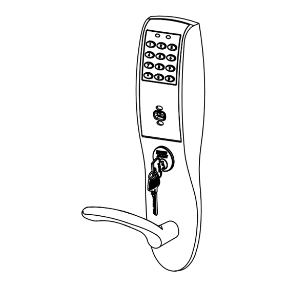
Profile Series v.G1.5/LK Mortise Lock General Description The SARGENT Profile v.G1.5/LK Mortise Lock is designed for areas which require stand alone authorized entry. It is a self-contained microprocessor-controlled keypad with non-volatile memory. The keypad holds a total of 100 (LK)/2000 (G1-LU, G1-PK, G1-PA, G1-TU, G1-TP, G1-TA) different user codes. User codes utilized for Master and Supervisory Codes, respectively. -
Page 4: Parts Breakdown
Pro le Series v.G1.5 Profile Series v.G1.5/LK Mortise Lock Parts Breakdown 18/19 18 19 17 20 27/28 800-810-WIRE (9473) • www.sargentlock.com • A7855B 1-800-810-WIRE • www.sargentlock.com • A7855C... - Page 5 Profile Series v.G1.5/LK Mortise Lock Parts Breakdown (Continued) ITEM PART No. DESCRIPTION REQ’D ITEM PART No. DESCRIPTION REQ’D 01-1212 Security Screw 82-4190 Outside Escutcheon with Cylinder Hole and Key Pad, or Key 01-0297 Security Tool Pad/Prox (G1-LU, G1-PK, G1-TU, G1-TP) 82-0507 Thumb Turn 82-4191...
-
Page 6: Installation Instructions
Profile Series v.G1.5/LK Mortise Lock Installation Instructions Step #1 – Verify Hand and Bevel of Door A. Verify Hand and Bevel of Door Stand on outside/locked side of door when determining the door hand LHRB RHRB Left Hand Left Hand Right Hand Right Hand Hinges Left... - Page 7 Profile Series v.G1.5/LK Mortise Lock Step #2 – How to Change Hand of Lockbody A. Reverse Lock Hand Red surface of locking piece must face the outside/locked side of door. To rotate locking piece (Fig. 2A): 1. Position lock body with red surface of locking piece visible. 2.
- Page 8 Profile Series v.G1.5/LK Mortise Lock Step #3 – Install Lock Body 1. Insert lock body into mortised cutout (Fig. 3A). Non-Cylinder Side 2. Hold lock body loosely in place with (2) lock body screws. Note: Do not completely tighten screws at this time. Harness exits Non-Cylinder side (2) #12-24 x 1/2”...
- Page 9 Profile Series v.G1.5/LK Mortise Lock Step #5 – Install Weatherseal Gasket (Exterior Doors) 1. Carefully remove the backing from the gasket. 2. Apply gasket to escutcheon: • Starting in one place, press the adhesive side of the gasket firmly against the escutcheon. •...
- Page 10 Profile Series v.G1.5/LK Mortise Lock Step #7 – Inside Escutcheon Wire Connections Images are shown without gasket. If gasket is necessary, refer to Step #5. Before the controller is attached to the door: Reader Ribbon 1. Attach the reader assembly Cable ribbon cable into the back of the controller assembly...
- Page 11 Profile Series v.G1.5/LK Mortise Lock Step #8 – Inside Lever Installation Inside of Door 1. Slide lever handle onto spindle until fully seated (Fig. 8A). 2. Insert #8-32 x 1-1/4” screws through inside escutcheon and thread into outside escutcheon. 3. Straighten escutcheons and tighten securely. 4.
- Page 12 Profile Series v.G1.5/LK Mortise Lock Outside of Door Step #10 – Attach Front Plate Attach front plate with (2) flat head screws. Front Plate (2) Flat Head Screws Fig. 10A Lock Body Screws Step #11 – Attach Battery Keeper and Cover 1.
- Page 13 Profile Series v.G1.5/LK Mortise Lock Step #12 – Install and Remove Batteries* A. Install Batteries and Keeper 1. Place (6) “AA” batteries into the compartment, being careful to properly align polarity (Fig. 12A). 2. To install battery keeper, insert the tabs on the bottom of the keeper into the battery compartment slots and press the keeper tightly against batteries and inserting tabs into bottom slots.
-
Page 14: Rf Technology Lock
Profile Series v.G1.5/LK Mortise Lock RF Technology Lock Flathead Through-bolt Installation for the RF Technology Lock for Antenna G1-TU, G1-TA, G1-TP is, for the most part, Board Antenna installed as described in section 6. Board Mounting In addition: Posts The antenna board must be carefully moved to access the upper through-bolt screw. - Page 15 Installation Notes 1. With new applications, an ElectroLynx® door harness with 8 and 4 pin connectors will be pre-installed inside door by ASSA ABLOY door manufacturer when specified during ordering process. 2. Wiring to pigtail harness is per facility wiring requirement.
- Page 16 Profile Series v.G1.5/LK Mortise Lock ElectroLynx Lock Wire Connections Door Position Switch (DPS) Install the SARGENT 3287 Door Status Switch according to instructions included in the kit. Wire the 3287 Door Status Switch to the ElectroLynx frame har- ness and to the door status wires: 1.
- Page 17 Installation 1. ElectroLynx® System Wiring Instructions (Fig. 1, 1A and Fig. 2): a. Look for the mating part on ASSA ABLOY doors and frames. b. Plug in all connectors during product installation (Fig. 2). c. Hard wire door status switch as shown 2.
- Page 18 Installation 1. ElectroLynx® System Wiring Instructions (Fig. 1, 1A and Fig. 3): a. Look for the mating part on ASSA ABLOY doors and frames. b. Plug in all connectors during product installation (Fig. 3). c. Hard wire hard power and/or remote unlock (REX) (Fig. 3).
- Page 19 Installation 1. ElectroLynx® System Wiring Instructions (Fig. 1, 1A and Fig. 3): a. Look for the mating part on ASSA ABLOY doors and frames. b. Plug in all connectors during product installation (Fig. 3). c. Hard wire hard power and/or remote unlock (REX) (Fig. 3).
-
Page 20: Operational Check
Profile Series v.G1.5/LK Mortise Lock Operational Check For devices with cylinders, insert key into cylinder and rotate. Check to see if: 1. The key retracts the latch. Key should rotate freely. Key should extend and retract the deadbolt (if applicable). 2. - Page 21 Profile Series v.G1.5 Mortise Lock Notes 1-800-810-WIRE • www.sargentlock.com • A7855C...
- Page 22 The company’s customer base includes commercial construction, institutional, and industrial markets. Copyright © 2014, Sargent Manufacturing Company, an ASSA ABLOY Group company. All rights reserved. Reproduction in whole or in part without the express written permission of Sargent Manufacturing Company is prohibited.
Need help?
Do you have a question about the SARGENT Profile v.G1.5/LK and is the answer not in the manual?
Questions and answers