Electrolux Professional IC6 48 Basic Series Installation Manual
Hide thumbs
Also See for IC6 48 Basic Series:
- Installation manual (80 pages) ,
- Installation manual (76 pages)
Table of Contents
Advertisement
Quick Links
Advertisement
Table of Contents

Related Manuals for Electrolux Professional IC6 48 Basic Series


Summary of Contents for Electrolux Professional IC6 48 Basic Series
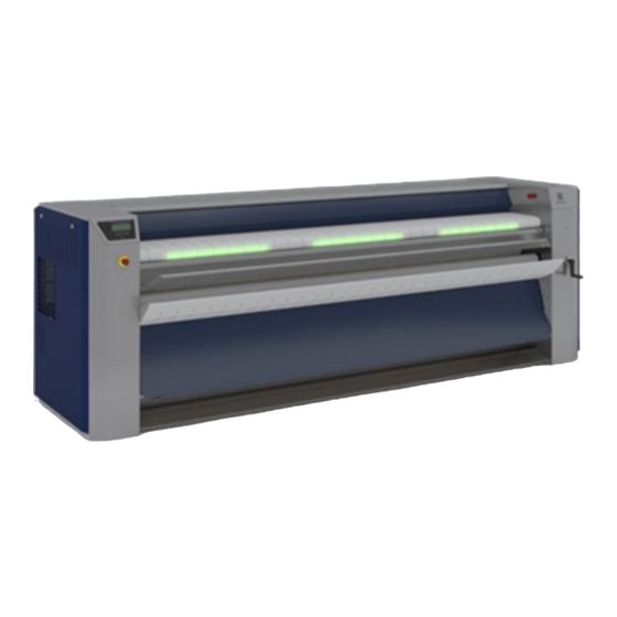
- Page 1 Installation manual Ironers IC6 48xx Basic/LF/FLF/R Original language 10102059/EN...
-
Page 3: Table Of Contents
Contents Contents 1 General instructions :...........................5 Environmental information ......................5 Ergonomics certification ......................6 Disposal information ........................7 1.3.1 Disposal of appliance at end of life ..................7 1.3.2 Disposal of packing ......................7 Preliminary instructions ......................7 1.4.1 Precautions for use......................9 1.4.2 Symbols ........................10 1.4.3 Personal protection equipment ..................11 1.4.4 Emergency stop ...................... - Page 4 Contents Supplies..........................62 Sound level ..........................62 Electric power supply : ......................63 4.5.1 TABLE 1 (in accordance with EN standard 60204–1)............64 4.5.2 TABLE 2 correction factors for different ambient temperatures : ........64 4.5.3 TABLE 3 correction factors for different cable insulating materials : ........64 4.5.4 TABLE 4 B2, C and E correction factors for cable grouping : ..........64 4.5.5 Calculation ........................65 4.5.6 Electrical Standard characteristics for IC6 48xx :...............65...
-
Page 5: General Instructions
Installation manual 1 General instructions : Caution All the illustrations in this manual do not necessarily represent your machine, but the action shown is always compatible with your product! 1.1 Environmental information Concerned by providing the end user with useful and necessary environmental information, we wish to precise: •... -
Page 6: Ergonomics Certification
Installation manual 1.2 Ergonomics certification The human body is designed for movement and activity but physical stress injuries as a result of static and repetitive movements or unfavorable working postures may occur. The ergonomic features of our product, the ones which may influence your physical and cognitive interaction with it, have been assessed and certified. -
Page 7: Disposal Information
Installation manual 1.3 Disposal information 1.3.1 Disposal of appliance at end of life Before disposing of the machine, make sure to carefully check its physical condition, and in particular any parts of the structure that can give or break during scrapping. The machine’s parts must be disposed of in a differentiated way, according to their different characteristics (e.g. - Page 8 Installation manual Do not use the machine unless it is plugged into a correctly earthed power socket complying with stand- ards in force. Caution This device must not be installed in places accessible to the public. Warning Make sure the machine is disconnected from the mains before repairing or servicing. Important Any repairing or maintenance operation should be carried out by a specialist.
-
Page 9: Precautions For Use
Installation manual Important It is specially advised not to install the machine on a synthetic floor covering. The frictional electricity may hinder the good working of the machine Under no circumstances should a gas-heating machine be installed in a building which includes a dry- cleaning machine. -
Page 10: Symbols
Installation manual 1.4.2 Symbols Caution. An exclamation mark inside an equilateral triangle offers the user important advice about usage, servicing, and hazard- ous conditions Caution, presence of dangerous current. A flash lightning with an arrow at its end inside an equilateral triangle , warns the user about the presence of uninsu- lated “dangerous current”... -
Page 11: Personal Protection Equipment
Installation manual 1.4.3 Personal protection equipment Given below is a summary table of the Personal Protection Equipment (PPE) to be used during the various phases of the machine’s service life. Phase Protection Safety Gloves Glasses Ear protectors Mask Safety helmet garments footwear Transport... -
Page 12: Note About The A.c. Power
Installation manual 1.5 Note about the A.C. power According to the EN 60204-1:1997 standard, the machine is provided for A.C. supplies corresponding to the ex- tracted characteristics below : 4.3.2 A.C. supplies Voltage: Steady state voltage: from 0.9 to 1.1 of nominal voltage. Frequency: from 0.99 to 1.01 of nominal frequency continuously. -
Page 13: Locking And Tagging Procedure
Installation manual 1.6 Locking and tagging procedure A red insert at the beginning of this instruction handbook schematically shows the locking and tagging procedure de- scribed below. If you wish, you can detach this insert and display it close to the machine to remind maintenance per- sonnel of the safety instructions. -
Page 14: Working Place Lighting
Installation manual Unlock the stop valves and the main switch. 1.7 Working place lighting The lighting should be designed so as to avoid eye strain for the operator ; it should be uniform without any glare, and should be sufficient to detect any hazards. The average lighting value on the working place recommended by the clothing industry for inspecting linen is 500 lux. -
Page 15: Handling
Installation manual 2 Handling Important It is obligatory that all these operations are undertaken by handling specialists. 2.1 Unpacking You should have found an instruction handbook and keys to open the machine casings, in the machine. Depending on its destination, the ironer is delivered bare or may be placed on a transport pallet and/or packed with plastic film. -
Page 16: Lifting With Handlings Straps
Installation manual 2.3 Lifting with handlings straps Lifting in that case can only be done with handling straps (C : minimum capacity 2500 daN / L : minimum length 4m) which bear weight of the machine. Caution Make sure to place the straps correctly to avoid any bending of parts of the machine. Caution In order to avoid any bending of casings, you should never climb and stand on top of the machine. -
Page 17: Installation
Installation manual 3 Installation : 3.1 Feeding boxes installation for Model IC6 48xx basic or LF Important Before putting the machine into service, it is compulsory to replace the feeding boxes in their functioning place. Caution To do so, it is recommended to handle the part for two people for very long machines (IC64825, IC64828 or IC64832) 3.1.1 Replace Low feeding box : Caution... -
Page 18: Replace Feeding Box
Installation manual 3.1.2 Replace feeding box : 1. Unscrew the 4 screws of the engagement tank 2. Remove the pan, being careful of collisions with the pan supports and other parts. It is recommended to handle the part to 2 people. 3. -
Page 19: Installation
Installation manual 3.2 Installation The ironer must be transported to its final position in the laundry before the pallet is removed. The installation must be done by competent technicians in accordance with local codes and regulations. When there are not local codes and regulations, the installation must be comply with European standards applicable. The machine must be installed on a perfectly even surface, strong and horizontal, capable resisting to the efforts shown in the technical characteristics. -
Page 20: How To Remove The Pallet
Installation manual 3.2.1 How to remove the pallet : When the pallet is putting in its right place, you can remove it by following these points depending of your enable tools : Remove the fixation (A) of red handling brackets from the pallet on each side of the machine. 3.2.1.1 Remove the pallet with a two-wheel forklift load : Once the machine is placed on the ground with the pallet, it is advisable to use a two-wheel forklift load as below to... - Page 21 Installation manual If this type of tool is unavailable, follow the procedure in the next chapter to remove the pallet from the machine. 3.2.1.2 Remove the pallet without a two-wheel forklift load : Equipment : • 01 x hydraulic cylinder •...
- Page 22 Installation manual • Wedge with 3 pieces of wood (400x70x60) 2 on thickness70 mm and 1 on the thickness 60mm. 2 (400x70x60) + 1 (400x70x60) = 2x70mm + 60 mm = 200 mm • Lower the right side of the machine on the wedges...
- Page 23 Installation manual STEP 2 : • Repeat STEP 1 on the left side of the machine. STEP 3 : • Remove the pallet. The same size as the machine, the pallet has to pass between the wedges without any problem. Warning...
- Page 24 Installation manual Remove the pallet in a straight line so as not to come into contact with the wedges holding the machine in suspension. STEP 4 : • For safety, wedge under the 2 box spar ( Front / Rear) as close as possible to the casing with same thickness of wedging as on the side of the machine : 3 pieces of wood (400x70x60) 2 on the thickness 70 mm and 1 on the thickness 60 mm..
- Page 25 Installation manual A delta of 45 mm is obtained between the two sides of the machine. STEP 10 : • Lift the machine and remove from the left side the wedge (400x70x60) 70 mm thick Right side : 1 (400x150x25) = 25 mm. Left side : machine on the ground.
-
Page 26: Levelling The Machine
Installation manual 3.2.2 Levelling the machine : Adjust the nuts with a spanner and adjust the dryer ironer so that it is horizontal and that its four stands are perfectly vertical. Check with a spirit level placed on the sole plate for the longitudinal direction and the machine top cover for the trans- verse direction (see below) The maximum stand height adjustment is 80 mm (3”) Tighten the lock nuts after adjustment for each pads. -
Page 27: Remove Of The Transport Locks Fitted
Installation manual 3.3 Remove of the transport locks fitted. Important Before putting the machine into service, it is compulsory to remove the different transport locks fitted. The machine should be in its right place before removing these transport locks. 3.3.1 Transport locks fitted inside the casing of the feeder for Model IC6 48xx FLF: To do so, remove the fixing screws of the red transportation bridles. -
Page 28: Transport Angles
Installation manual 3.3.2 Transport angles : Screw off the screws to remove the 2 red transport angles (B) with a key. Caution Do not remove this screws. Keep this angles to eventually lift the machine. Block the screws which maintained this angles. -
Page 29: Electrical Connection
Installation manual 3.4 Electrical connection Prior to use, the machine should be plugged into a correctly earthed power socket complying with the standard in force. Important The mechanical and electrical installation of the machine should only be done by qualified personnel. Important Make sure that both the power voltage is correct and the power supply of your installation is sufficient before con- necting the machine.Use only a cable to supply the machine. - Page 30 Installation manual Pass The power supply cable of the machine through the stuffing box (A) on the top of the left casing. In order to know all machines technical characteristics concerning electricity (connection, wiring,...) referes to chapter in appendices For each machine, install a fixed multipole circuit breaker ( or fuses protector) in the laundry main caninet.
- Page 31 Installation manual...
- Page 32 Installation manual Mains transformer connection diagrams according to the customer’s various mains voltage (machines pro- vided with a transformer only). 400 Volts supply Measure the mains voltage at the primary with a volt- meter (V) between 0 and 400 volts of the transformer. If the voltage is equal to 400 volts, do not touch the transformer connection which should be as indicated in the margin.
- Page 33 Installation manual Important Once connected, make sure to check the correct order of phase connections. (see chapter operating inspection below)
-
Page 34: Connection Diagrams For The Control Circuit Power Supply (T2)
Installation manual 3.4.1 Connection diagrams for the control circuit power supply (T2) The tension of the control circuit delivered by the power supply must be 24 volts dc. The supply tension for your ma- chine is normally 230/400 volts between phases, this tension can however be different. The potentiometer (A) allows to adjust the tension. - Page 35 Installation manual Before starting the machine, do not push the circuit breakers Q5 and Q701 in the electrical cabinet before checking the fan’s rotation direction. For few seconds, manually activate the breaker that drive the fan motor : Check on the electrical drawing for the breaker name. Then visually check the rotation way of the turbine. A sticker in- dicate the correct rotation way.
-
Page 36: Connection Of The Ironer Evacuation System
Installation manual 3.5 Connection of the ironer evacuation system : You should have found an instruction handbook and keys to open the machine casings, in the machine. Depending o,n its destination, the ironer is delivered bare or may be placed on a transport pallet and/or packed with plastic film. -
Page 37: Fresh Air Inlet
Installation manual 3.5.1 Fresh air inlet To allow the dryer ironer to work at its best, it is important that the laundry air inlet passes through an opening from the outside. The fresh air arrival must be equivalent to the volume of evacuated air (please refer to the output of the fans at zero pressure in the technical characteristics) Important In the case of several machines, these values should be added together. -
Page 38: Evacuation Duct
Installation manual 3.5.2 Evacuation duct It is recommended that a separate smooth-walled evacuation duct should be connected to each dryer, providing the least possible resistance to air. Check that the shaft flow is at least twice the capacity of the ironer exhaust fan. Danger To prevent any risk of burnings, the vapours’evacuation duct of the flatwork ironers of the linen has to be insu- lated (to be done by the customer) -
Page 39: Exhaust Pipes Pressure Control
Installation manual 3.5.4 Exhaust pipes pressure control : In order to achieve proper operation, this exhaust pipes must always be kept as short as possible and must have as few bends as possible. If an outlet channel joins a main channel, the angle of incidence must not exceed 45°. If the distance from the outlet channel is bigger than xx meters, a series fans must be installed further down the outlet channel or the section of the pipe must be increased. -
Page 40: Evacuation System If Several Dryers Are Connected To A Common Evacuaton Duct (Except Gas Heating Machines)
Installation manual 3.5.5 Evacuation system if several dryers are connected to a common evacuaton duct (except gas heating machines): If several ironers are installed with a common evacuation duct, the cross section of the evacuation duct must in- crease as a function of the number of installed machines so that each of them operates at the same value of air resistance.. -
Page 41: Steam And Condensate Connections
Installation manual 3.6 Steam and condensate connections : There is always a risk that a certain amount of water will be carried in steam. Water is carried in the lower parts of the supply tubes, and steam in the upper parts. Make a swan neck branch-T on the main tube to prevent this water damaging the machine heating system. -
Page 42: Steam Connection Dn 20 (3/4" Bsp)
Installation manual 3.6.1 Steam connection DN 20 (3/4” BSP) : The customer must install a line purge, a manually closing valve with handwheel lockable in off position (do not use a 1/4 turn valve) and a filter on the supply side of the ironer. The customer must install a safety valve if the boiler used operates at a pressure over the acceptable vapour of 1000 kPa maxi (10 bar). -
Page 43: Approval
Installation manual 3.6.3 D.E.S.P. approval This technical form for pressure concerns an assembly constituted of : - a cylinder classified in category of risk IV according to article 4 and Annex II of Directive 2014/68 / UE, - pipings (DN20) responding to the article 4 point 3 of Directive 2014/68 /UE. Manufacturer : Electrolux Laundry System France SNC 52, Rue Pasteur... -
Page 44: Gas Connection
Installation manual 3.7 Gas connection : Caution The installation, connection and gas arrival adjustments for the machine must be done by qualified personnel only. -
Page 45: Gas Supply Dn 20 (3/4" Bsp)
Installation manual 3.7.1 Gas supply DN 20 (3/4” BSP) : The customer must install a filter and a manual stop valve on the supply side of the machine if natural gas is used. For butane or propane, the customer must install a filter, a manual closing valve and a pressure reducer. Connect the installation at the back of the machine. -
Page 46: Determinate The Gas Type
Installation manual If the gas inlet pressure (P1) is identical to the nominal pressure of the machine (P2), it is possible to insert a reser- voir as close as possible to the machine in order to protect against any falls in pressure when the machine starts up. Anfd increase the diameter of gas pipe supply to allow the flow rate. -
Page 47: Check Before Use
Installation manual 3.8 Check before use 3.8.1 Positioning roller rotation check The rollers located between the drive disk and the cylinder in the right hand unit must not rotate continuously while the machine is operating. Caution This check must be carried out when you install the machine and once a month. If the rollers rotate permanently, you must call the technician to adjust the plate to avoid mechanical wear on the cylinder. -
Page 48: Model : Ic6 48Xx Basic
Installation manual 1 : Identification plate 2 : Adjustment label (for gas machine only) 4.1.1 Model : IC6 48xx basic : Ironing width Units 1.9 m 2.1 m 2.5 m 2.8 m 3.2 m Packaging dimensions (pallet or crate) Length (A) 2720 2930 3350... -
Page 49: Model : Ic6 48Xx Lf Length Folding
Installation manual 4.1.2 Model : IC6 48xx LF Length Folding: Ironing width Units 1.9 m 2.1 m 2.5 m 2.8 m 3.2 m Packaging dimensions (pallet or crate) Length (A) 2720 2930 3350 3550 3980 Width (B) 1200 1200 1200 1200 1200 Height (C) pallet... -
Page 50: Model : Ic6 48Xx R Rear Load Removal
Installation manual 4.1.4 Model : IC6 48xx R Rear load removal: Ironing width Units 1.9 m 2.1 m 2.5 m 2.8 m 3.2 m Packaging dimensions (pallet or crate) Length (A) 2780 2980 3410 3620 4040 Width (B) 1775 1775 1775 1775 1775... -
Page 51: Technical Characteristics
Installation manual 4.2 Technical characteristics 4.2.1 Model : IC6 48xx Basic First level : Front View Second level : Back view and Left View Third level : Top View... - Page 52 Installation manual Characteristics / type machine Units 4819 4821 4825 4828 4832 Overall width 2575 2785 3205 3415 3835 Ironer width 1910 2120 2540 2750 3170 Width between feet 2300 2510 2930 3140 3560 Cylinder diameter Gas / Electric heating Cylinder diameter Steam heating Effective working width 1910...
- Page 53 Installation manual Maximum electrical consumption Maximum steam consumption at 900 kPa kg/h Inner volume steam cylinder Max. water evaporation capacity With 50 kg/h % residual moisture content and 100 % cylinder utilization (according to ISO 93.98 standard). Heat loss (3% of installed heating power)
-
Page 54: Model : Ic6 48Xx Lf Length Folding
Installation manual 4.2.2 Model : IC6 48xx LF Length Folding First level : Front View Second level : Back view and Left View Third level : Top View... - Page 55 Installation manual Characteristics / type machine Units 4819 4821 4825 4828 4832 Overall width 2575 2785 3205 3415 3835 Ironer width 1910 2120 2540 2750 3170 Width between feet 2300 2510 2930 3140 3560 Cylinder diameter Gas / Electric heating Cylinder diameter Steam heating Effective working width 1910...
- Page 56 Installation manual Maximum electrical consumption Maximum steam consumption at 900 kPa kg/h Inner volume steam cylinder Max. water evaporation capacity With 50 kg/h % residual moisture content and 100 % cylinder utilization (according to ISO 93.98 standard). Heat loss (3% of installed heating power)
-
Page 57: Model : Ic6 48Xx Flf Feeder Length Folding
Installation manual 4.2.3 Model : IC6 48xx FLF Feeder Length Folding First level : Front View Second level : Back view andLeft View Third level : Top View... - Page 58 Installation manual Characteristics / type machine Units 4819 4821 4825 4828 4832 Overall width 2575 2785 3205 3415 3835 Ironer width 1910 2120 2540 2750 3170 Width between feet 2300 2510 2930 3140 3560 Cylinder diameter Gas / Electric heating Cylinder diameter Steam heating Effective working width 1910...
- Page 59 Installation manual Maximum electrical consumption Maximum steam consumption at 900 kPa kg/h Inner volume steam cylinder Max. water evaporation capacity With 50 kg/h % residual moisture content and 100 % cylinder utilization (according to ISO 93.98 standard). Heat loss (3% of installed heating power)
-
Page 60: Model : Ic6 48Xx R With Rear Load Removal
Installation manual 4.2.4 Model : IC6 48xx R with Rear load removal First level : Front View Second level : Left View Third level : Back view andTop View... - Page 61 Installation manual Characteristics / type machine Units 4819 4821 4825 4828 4832 Overall width 2575 2785 3205 3415 3835 Ironer width 1910 2120 2540 2750 3170 Width between feet 2300 2510 2930 3140 3560 Cylinder diameter Gas / Electric heating Cylinder diameter Steam heating Effective working width 1910...
-
Page 62: Supplies
Installation manual Maximum electrical consumption Maximum steam consumption at 900 kPa kg/h Inner volume steam cylinder Max. water evaporation capacity With 50 kg/h % residual moisture content and 100 % cylinder utilization (according to ISO 93.98 standard). Heat loss (3% of installed heating power) 4.3 Supplies You can take the box placed inside of the casing. -
Page 63: Electric Power Supply
Installation manual Point A Point B Flatwork ironer folder (LF) Point C Point D Point A Point B Feeder flatwork ironer folder (FLF) Point C Point D Point A Point B Flatwork ironer with rear load re- moval (R) Point C Point D Point A Point B... - Page 64 Installation manual 4.5.1 TABLE 1 (in accordance with EN standard 60204–1) Values given for : Cable with copper conductors. Cable with PVC insulation (for other insulants see TABLE 3). Ambient temperature 40°C max. (for others see TABLE 2) Three-phase cable under load without including starting currents. BT / C / E cable layout.
-
Page 65: Calculation
Installation manual 4.5.5 Calculation The total current included for usint Table 1 should be the maximum rated current for the machine divided by the prod- uct of the different correction factors. Other correction factors may also be applied ; consult cable manufacturers. Calculation : example The machine has a rated current of 60 A The ambient temperature is 45°C ;... -
Page 66: Gas Setting Characteristics Ic6 48Xx Ffs
Installation manual 4.6 Gas setting characteristics IC6 48xx FFS : Caution The installation, connection and gas arrival adjustments for the machine must be done by qualified personnel only. -
Page 67: Legend Of Symbols Used
Installation manual 4.6.1 Legend of symbols used : • I : Machine working with only one gas family • II : Machine working with two gas families • 1 : 1st family : caol gas or town gas (for information : not used here) •... -
Page 68: Testing Pressure
Installation manual 4.6.2 Testing pressure : According to the EN 437 standard, the values of the testing pressures mentionned in our various documents are val- ues for static pressures taken at the gas inlet connection of the machine ; heating of the machine being on. -
Page 69: Setting Gas Adjustment
Installation manual 4.6.3 Setting gas adjustment : The machine is adjusted at the plant to be suitable for the kind of gas specified on the order. If you have to supply your machine with gas in a familly different from the gas for which your machine was adjusted , proceed as follows : Check that the diameter of the injectors is adequate for the kind of gas of your installation (see Table of injectors be- low). - Page 70 Installation manual Important Adjustments should be made by qualified personnel only.
-
Page 71: Adjustment And Checking Of The Outlet Pressure
Installation manual 4.6.4 Adjustment and checking of the outlet pressure The gas outlet pressure of the solenoid valve is adjusted at the factory. If you have to make another adjustment, pro- ceed as follows : • A : Inlet • B : Outlet •... - Page 72 Installation manual 1 : Close the gas inlet and remove the binding screw from the pres- sure tapping (F) and connect the manometer tube. 2 : The electricity supply must be energized otherwise gas will not be supplied to the burner. 3 : Open and check the gas inlet main burner using the manometer on the pressure tapping (F) 4 : Remove pressure regulator cap (D)
-
Page 73: Tables Of Correspondences
Installation manual 4.6.5 Tables of Correspondences : TABLE OF CORRESPONDENCES : IRONER 4819 Working Heat emission Consumption Pressure at Consumption Diameter of Category Type supply injectors injectors Index of Gas pressure in kW (Hi) in kg/h in mm in mm H2O in M3/h in mbar *2E, 2H ,... - Page 74 Installation manual 46.34 MJ/kg 2.10 5.05 * For Belgium, no work is allowed between G20 and G25 Important G20 (H) = natural gas , Lacq Type (20 mbar)G25 (L) = natural gas , Groningue Type (20 or 25 mbar)G30 (H) = Butane gas (28/30, 50 mbar)G31 = Propane gas (28/30, 37 , 50 mbar) Important Tightness test after installationThe gas leak test is performed as follows :1/ Paint pipe joints, pilot gas tubing con-...
-
Page 75: Explanation Of Washing Symbols
Installation manual 4.7 Explanation of washing symbols (ISO 3758:2005 standard) To overcome language barriers, the following are symbols used internationally to give you guidance and recommen- dations when washing different textiles. 4.7.1 Washing The tub symbolizes washing. Max. washing tem- Symbols Mechanical action perature in °C... -
Page 76: Bleaching
Installation manual 4.7.2 Bleaching The triangle symbolizes bleaching. Symbols Explanation Bleaching allowed (chlorine or oxygen). Bleaching allowed (only oxygen). Do not bleach. 4.7.3 Drying The circle in a square symbolizes tumble drying. Symbols Explanation Can be put in a tumble dryer. Normal temperature. -
Page 77: Dry Or Water Cleaning
Installation manual 4.7.5 Dry or water cleaning The circle symbolizes dry or water cleaning. Symbols Explanation Normal dry cleaning with perchloroethyl, solvent of hydrocarb. Mild dry cleaning with perchloroethyl, sol- vent of hydrocarb. Normal dry cleaning with solvent of hydrocarbon. Mild dry cleaning with solvent of hydrocarbon. -
Page 78: Conversion Of Measurement Units
Installation manual 4.8 Conversion of measurement units This following is a list of correspondences of the main frequency used units, to avoid the need to use measurement unit conversion table. 1 bar = 100 000 Pa British thermal unit 1 Btu = 1 055.06 J 1 bar = 1.019 7 kg/cm²... - Page 80 Electrolux Professional AB 341 80 Ljungby, Sweden www.electroluxprofessional.com...
Need help?
Do you have a question about the IC6 48 Basic Series and is the answer not in the manual?
Questions and answers