
Subscribe to Our Youtube Channel
Related Manuals for Kobold DAG-M1F


Summary of Contents for Kobold DAG-M1F
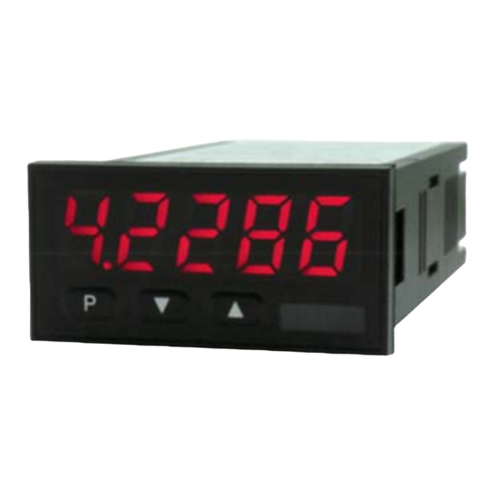
- Page 1 Operating Instructions Digital Indicator and Controller for Panel Mounting Model: DAG-M1F...
-
Page 2: Table Of Contents
Error elimination ..................39 Disposal ...................... 40 EU Declaration of Conformance ..............41 Manufactured and sold by: Kobold Messring GmbH Nordring 22-24 D-65719 Hofheim Tel.: +49(0)6192-2990 Fax: +49(0)6192-23398 E-Mail: info.de@kobold.com Internet: www.kobold.com page 2 DAG-M1F K05/0123... -
Page 3: Note
Please read these operating instructions before unpacking and putting the unit into operation. Follow the instructions precisely as described herein. The instruction manuals on our website www.kobold.com are always for currently manufactured version of our products. Due to technical changes, the instruction manuals available online may not always correspond to the product version you have purchased. -
Page 4: Brief Description
DAG-M1F 5. Brief description The panel meter DAG-M1F can evaluate pulses in many different ways and show the result in the 5-digit LED-display. Available options are: frequency coverage with optional filters, summate of pulses or display values via the time, detection of a rotational speed or collection of a position via an incremental encoder. -
Page 5: Assembly
3. Click the fixing elements back into place and tighten the clamping screws by hand. Then use a screwdriver to tighten them another half a turn. CAUTION! The torque should not exceed 0.1 Nm! The dimension symbols can be exchanged before installation via a channel on the side! DAG-M1F K05/0123 page 5... -
Page 6: Electrical Connection
Frequency 0.01Hz to 9.9999 kHz with speed transmitter / 0 to 2.5000 kHz at position survey Attention! For Namur sensors with a nominal voltage of approx. 8 V, a sensor supply of 12 VDC is needed! page 6 DAG-M1F K05/0123... - Page 7 DAG-M1F Connection examples: DAG-M1F K05/0123 page 7...
-
Page 8: Function And Operation Description
Pressing the navigation keys leads to a break-off the value input and to a change into the menu level. All adjustments are saved automatically by the device and changes into operating mode, if no further key operation is done within the next 10 seconds. page 8 DAG-M1F K05/0123... - Page 9 DAG-M1F Function chart: DAG-M1F K05/0123 page 9...
-
Page 10: Setting Up The Device
/ display mode. 9.2 Standard parameterization (flat operation level) To parameterize, press the [P] key in operating mode for 1 second. The display then changes to the menu level with the first menu item TYPE. page 10 DAG-M1F K05/0123... - Page 11 DAG-M1F DAG-M1F K05/0123 page 11...
- Page 12 DAG-M1F page 12 DAG-M1F K05/0123...
- Page 13 DAG-M1F DAG-M1F K05/0123 page 13...
- Page 14 DAG-M1F page 14 DAG-M1F K05/0123...
-
Page 15: Programming Interlock "Run
DAG-M1F 9.3 Programming interlock “run” DAG-M1F K05/0123 page 15... -
Page 16: Extended Parameterization (Professional Operation Level)
DAG-M1F Extended parameterization (Professional operation level) 9.4.1 Signal input parameters page 16 DAG-M1F K05/0123... - Page 17 DAG-M1F DAG-M1F K05/0123 page 17...
- Page 18 DAG-M1F page 18 DAG-M1F K05/0123...
- Page 19 DAG-M1F DAG-M1F K05/0123 page 19...
- Page 20 DAG-M1F 9.4.2 General device parameters page 20 DAG-M1F K05/0123...
- Page 21 DAG-M1F DAG-M1F K05/0123 page 21...
- Page 22 DAG-M1F page 22 DAG-M1F K05/0123...
- Page 23 DAG-M1F 9.4.3 Safety parameters DAG-M1F K05/0123 page 23...
- Page 24 DAG-M1F 9.4.4 Analog output parameters for analogue output page 24 DAG-M1F K05/0123...
- Page 25 DAG-M1F DAG-M1F K05/0123 page 25...
- Page 26 DAG-M1F 9.4.5 Relay functions page 26 DAG-M1F K05/0123...
- Page 27 DAG-M1F 9.4.6 Alarm parameters DAG-M1F K05/0123 page 27...
- Page 28 DAG-M1F page 28 DAG-M1F K05/0123...
- Page 29 DAG-M1F 9.4.7 Totalizer (Volume measurement) DAG-M1F K05/0123 page 29...
-
Page 30: Reset To Factory Settings
With reset, the default values of the program table are loaded and used for subsequent operation. This sets the unit back to the state in which it was supplied. Caution! All application-related data are lost. page 30 DAG-M1F K05/0123... -
Page 31: Alarms / Relays
This device has 4 virtual alarms that can monitor one limit value in regard of an undercut exceedance. Each alarm can be allocated to an optional relay output S1- S4. Furthermore, alarms can be controlled by events like e.g. hold or min/max value. DAG-M1F K05/0123 page 31... - Page 32 The switching-off delay operates in the same way, keeps the alarm / the relay switched longer for the parameterized time. page 32 DAG-M1F K05/0123...
-
Page 33: Programmer Examples
On a manually operated bender for sheet metal the bending angle shall be displayed in degree. The device is in zero state (0°) during switching on of the display. An incremental encoder with 360 pulses/rotation is used. DAG-M1F K05/0123 page 33... - Page 34 Based on the default settings of the display, the following parameters need to be changed: If the frequency needs to be displayed with a position after decimal point, then a 60 has to be selected as final value for this adjustment. page 34 DAG-M1F K05/0123...
- Page 35 U/min. 0…3600 U/min is preset as rotation speed range of the machine. Calculation of the input frequency Number of sprockets Rotation speed = 3600 U/min Setting up the device Based on the default settings of the device, following parameters need to be changed: DAG-M1F K05/0123 page 35...
-
Page 36: Technical Information
DAG-M1F 13. Technical Information Operating instructions, data sheet, approvals and further information via the QR code on the device or via www.kobold.com 14. Order Codes Operating instructions, data sheet, approvals and further information via the QR code on the device or via www.kobold.com 15. -
Page 37: Safety Advices
Any electrical connection deviating from the connection diagram can endanger human life and/or can destroy the equipment. The terminal area of the devices is part of the service. Here electrostatic discharge needs to be avoided. Attention! High voltages can cause dangerous body currents. DAG-M1F K05/0123 page 37... - Page 38 Galvanic isolated potentials within one complex need to be placed on an appropriate point (normally earth or machines ground). So, a lower disturbance sensibility against impacted energy can be reached and dangerous potentials, that can occur on long lines or due to faulty wiring, can be avoided. page 38 DAG-M1F K05/0123...
-
Page 39: Error Elimination
DAG-M1F 17. Error elimination DAG-M1F K05/0123 page 39... -
Page 40: Disposal
(Cd, Hg, Li or Pb) of the heavy metal that is decisive for the classification as containing pollutants: 1. „Cd" stands for cadmium 2. „Hg" stands for mercury 3. „Pb" stands for lead 4. „Li" stands for lithium Electrical and electronic equipment page 40 DAG-M1F K05/0123... -
Page 41: Eu Declaration Of Conformance
DAG-M1F 19. EU Declaration of Conformance We, KOBOLD Messring GmbH, Hofheim-Ts, Germany, declare under our sole responsibility that the product: Digital Indicating Unit model: DAG-M1F to which this declaration relates is in conformity with the standards noted below: EN 61010-1:2010 + A1:2019 + A1:2019/AC:2019...
Need help?
Do you have a question about the DAG-M1F and is the answer not in the manual?
Questions and answers