
Related Manuals for Kobold DAG-M12


Summary of Contents for Kobold DAG-M12
- Page 1 Operating Instructions Digital Indicator and Controller for Panel Mounting Pt100 2-/3-/4-wire -200°C…850°C / -328°F…1562°F Model: DAG-M12...
-
Page 2: Table Of Contents
Error elimination ..................25 Disposal ...................... 26 EU Declaration of Conformance ..............27 Manufactured and sold by: Kobold Messring GmbH Nordring 22-24 D-65719 Hofheim Tel.: +49(0)6192-2990 Fax: +49(0)6192-23398 E-Mail: info.de@kobold.com Internet: www.kobold.com page 2 DAG-M12 K05/0123... -
Page 3: Note
Please read these operating instructions before unpacking and putting the unit into operation. Follow the instructions precisely as described herein. The instruction manuals on our website www.kobold.com are always for currently manufactured version of our products. Due to technical changes, the instruction manuals available online may not always correspond to the product version you have purchased. -
Page 4: Brief Description
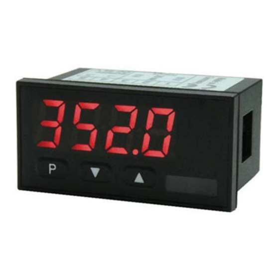
DAG-M12 5. Brief description The panel meter instrument DAG-M12 is a 5-digit device for Pt100 temperature sensors and a visual threshold value monitoring via the display. The configuration happens via three keys at the front. The integrated programming interlock prevents unrequested changes of parameters and can be unlocked again with an individual code. -
Page 5: Electrical Connection
DAG-M12 7. Electrical connection Type DAG-M123000R Supply of 24 VDC DAG-M12 K05/0123 page 5... -
Page 6: Function Description And Operation
Pressing the [0] key (Zero-key) leads to a break-off of the value input and to change into the menu level. All adjustments are saved automatically by the device and it changes into operating mode, if no further key operation is done within the next 10 seconds. page 6 DAG-M12 K05/0123... - Page 7 DAG-M12 Function chart DAG-M12 K05/0123 page 7...
-
Page 8: Setting Up The Device
/ display mode. 9.2 Standard parameterization (Flat operation level) To parameterize the display, press the [P] key in operating mode for 1 second. The display then changes to the menu level with the first menu item TYPE. page 8 DAG-M12 K05/0123... - Page 9 DAG-M12 DAG-M12 K05/0123 page 9...
-
Page 10: Programming Interlock
DAG-M12 9.3 Programming interlock page 10 DAG-M12 K05/0123... -
Page 11: Extended Parameterization (Professional Operation Level)
DAG-M12 9.4 Extended parameterization (Professional operation level) 9.4.1 Signal input parameters DAG-M12 K05/0123 page 11... - Page 12 DAG-M12 9.4.2 General device parameters page 12 DAG-M12 K05/0123...
- Page 13 DAG-M12 DAG-M12 K05/0123 page 13...
- Page 14 DAG-M12 9.4.3 Safety parameters page 14 DAG-M12 K05/0123...
- Page 15 DAG-M12 9.4.4 Analogue output parameters DAG-M12 K05/0123 page 15...
- Page 16 DAG-M12 page 16 DAG-M12 K05/0123...
- Page 17 DAG-M12 9.4.5 Relay functions DAG-M12 K05/0123 page 17...
- Page 18 DAG-M12 page 18 DAG-M12 K05/0123...
- Page 19 DAG-M12 9.4.6 Alarm parameters DAG-M12 K05/0123 page 19...
- Page 20 DAG-M12 Programming interlock run Description see page 10 menu level RUN page 20 DAG-M12 K05/0123...
-
Page 21: Reset To Factory Settings
This device has 4 virtual alarms that can monitor one limit value in regard of an undercut or exceedance. Each alarm can be allocated to an optional relay output S1-S2. Furthermore, alarms can be controlled by events like e.g. min/max value. DAG-M12 K05/0123 page 21... - Page 22 The switching-off delay operates in the same way, keeps the alarm / the relay switched longer for the parameterized time. page 22 DAG-M12 K05/0123...
-
Page 23: Technical Information
DAG-M12 12. Technical Information Operating instructions, data sheet, approvals and further information via the QR code on the device or via www.kobold.com 13. Order Codes Operating instructions, data sheet, approvals and further information via the QR code on the device or via www.kobold.com 14. -
Page 24: Safety Advices
The device is not suitable for installation in areas where there is a risk of explosion. Any electrical connection deviating from the connection diagram can endanger human life and/or can destroy the equipment. The terminal area of the devices is part of the service. Here electrostatic page 24 DAG-M12 K05/0123... -
Page 25: Error Elimination
(normally earth or machines ground). So, a lower disturbance sensibility against impacted energy can be reached and dangerous potentials, that can occur on long lines or due to faulty wiring, can be avoided. 16. Error elimination DAG-M12 K05/0123 page 25... -
Page 26: Disposal
(Cd, Hg, Li or Pb) of the heavy metal that is decisive for the classification as containing pollutants: 1. „Cd" stands for cadmium 2. „Hg" stands for mercury 3. „Pb" stands for lead 4. „Li" stands for lithium Electrical and electronic equipment page 26 DAG-M12 K05/0123... -
Page 27: Eu Declaration Of Conformance
DAG-M12 18. EU Declaration of Conformance We, KOBOLD Messring GmbH, Hofheim-Ts, Germany, declare under our sole responsibility that the product: Digital Indicating Unit model: DAG-M12V to which this declaration relates is in conformity with the standards noted below: EN 61010-1:2010 + A1:2019 + A1:2019/AC:2019...
Need help?
Do you have a question about the DAG-M12 and is the answer not in the manual?
Questions and answers