
Related Manuals for Kobold DAG-M3V Series


Summary of Contents for Kobold DAG-M3V Series
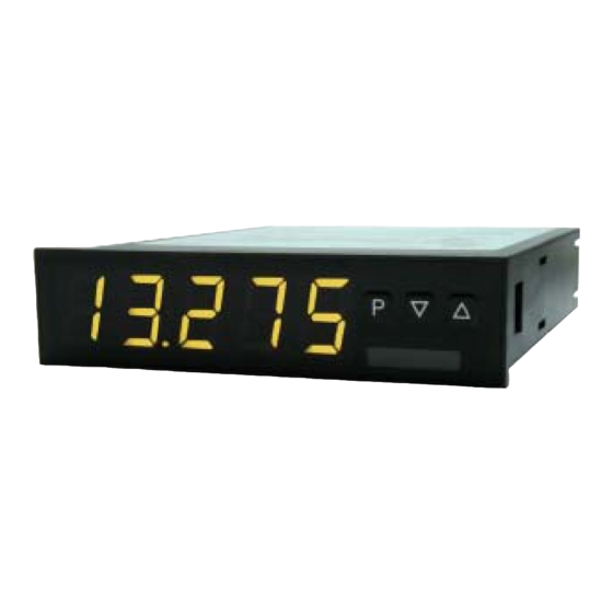
- Page 1 Operating Instructions Digital Indicating Unit Standard signals 0/4-20 mA, 0-10 VDC Model: DAG-M3V…, 96 x 24 mm...
-
Page 2: Table Of Contents
DAG-M3V We don’t accept warranty and liability claims neither upon this publication nor in case of improper treatment of the described products. The document may contain technical inaccuracies and typographical errors. The content will be revised on a regular basis. These changes will be implemented in later versions. - Page 3 DAG-M3V Manufactured and sold by: Kobold Messring GmbH Nordring 22-24 D-65719 Hofheim Tel.: +49(0)6192-2990 Fax: +49(0)6192-23398 E-Mail: info.de@kobold.com Internet: www.kobold.com DAG-M3V K06/0823 page 3...
-
Page 4: Note
Please read these operating instructions before unpacking and putting the unit into operation. Follow the instructions precisely as described herein. The instruction manuals on our website www.kobold.com are always for currently manufactured version of our products. Due to technical changes, the instruction manuals available online may not always correspond to the product version you have purchased. -
Page 5: Regulation Use
DAG-M3V 4. Regulation Use Any use of the device, which exceeds the manufacturer’s specification, may invalidate its warranty. Therefore, any resulting damage is not the responsibility of the manufacturer. The user assumes all risk for such usage. 5. Brief description The panel meter instrument DAG-M3V is a 5-digit device for direct current / direct voltage signals and a visual threshold value monitoring via the display. -
Page 6: Assembly
DAG-M3V 6. Assembly Please read the Safety advices on page 36 before installation and keep this user manual for future reference. 1. After removing the fixing elements, insert the device. 2. Check the seal to make sure it fits securely. 3. -
Page 7: Electrical Connection
DAG-M3V 7. Electrical Connection Type DAG-M3V8 supply 100-240 VAC 50/60Hz, DC ±10% Type DAG-M3V7 supply 10-40 VDC galv. Isolated, 18-30 VAC 50/60Hz Connection examples Below please find some connection examples that show practical applications. For devices with current inputs / Voltage inputs, without sensor supply. DAG-M3V K06/0823 page 7... - Page 8 DAG-M3V DAG-M3V devices With current respectively voltage input in combination with a 24 VDC sensor supply. page 8 DAG-M3V K08/0623...
-
Page 9: Function Description And Operation
DAG-M3V 8. Function description and operation Operation The operation is divided into three different levels. Menu level (delivery status) This level is for the standard settings of the device. Only menu items which are sufficient to set the device into operation are displayed. To get into the professional level, run through the menu level and parameterize “prof”... - Page 10 DAG-M3V Function chart: page 10 DAG-M3V K08/0623...
-
Page 11: Setting Up The Device
DAG-M3V 9. Setting up the device 9.1 Switching on Once the installation is complete, you can start the device by applying the voltage supply. Before, check once again that all electrical connections are correct. Starting sequence For 1 second during the switching-on process, the segment test (8 8 8 8 8) is displayed followed by an indication of the software type and, after that also for 1 second the software version. - Page 12 DAG-M3V page 12 DAG-M3V K08/0623...
- Page 13 DAG-M3V DAG-M3V K06/0823 page 13...
-
Page 14: Programming Interlock Run
DAG-M3V 9.3 Programming interlock RUN page 14 DAG-M3V K08/0623... -
Page 15: Extended Parameterization (Professional Operation Level)
DAG-M3V 9.4 Extended parameterization (Professional operation level) 9.4.1 Signal input parameters DAG-M3V K06/0823 page 15... - Page 16 DAG-M3V page 16 DAG-M3V K08/0623...
- Page 17 DAG-M3V DAG-M3V K06/0823 page 17...
- Page 18 DAG-M3V 9.4.2 General device parameters page 18 DAG-M3V K08/0623...
- Page 19 DAG-M3V DAG-M3V K06/0823 page 19...
- Page 20 DAG-M3V page 20 DAG-M3V K08/0623...
- Page 21 DAG-M3V DAG-M3V K06/0823 page 21...
- Page 22 DAG-M3V page 22 DAG-M3V K08/0623...
- Page 23 DAG-M3V 9.4.3 Safety parameters DAG-M3V K06/0823 page 23...
- Page 24 DAG-M3V 9.4.4 Serial parameters page 24 DAG-M3V K08/0623...
- Page 25 DAG-M3V 9.4.5 Analogue output parameters DAG-M3V K06/0823 page 25...
- Page 26 DAG-M3V page 26 DAG-M3V K08/0623...
- Page 27 DAG-M3V 9.4.6 Relay functions DAG-M3V K06/0823 page 27...
- Page 28 DAG-M3V 9.4.7 Alarm parameters page 28 DAG-M3V K08/0623...
- Page 29 DAG-M3V DAG-M3V K06/0823 page 29...
- Page 30 DAG-M3V 9.4.8 Totalizer (volume metering) page 30 DAG-M3V K08/0623...
-
Page 31: Reset To Default Values
DAG-M3V Programming interlock RUN Description see page 14, menu level RUN 10. Reset to default values To return the unit to a defined basic state, a reset can be carried out to the default values. The following procedure should be used: ... -
Page 32: Alarms / Relays
DAG-M3V 11. Alarms / Relays This device has 8 virtual alarms that can monitor one limit value in regard of an undercut or exceedance. Each alarm can be allocated to an optional relay output S1-S2; furthermore, alarms can be controlled by events like e.g. Hold or min-/max. value. - Page 33 DAG-M3V Operating current By operating current the alarm S1-S2 is off below the threshold and on on reaching the threshold. Quiescent current By quiescent current the alarm S1-S2 is on below the threshold and switched off on reaching the threshold. Switching-on delay The switching-on delay is activated via an alarm and e.g.
-
Page 34: Interfaces
DAG-M3V 12. Interfaces The interface RS485 is connected via a screened data line with twisted wires (Twisted-Pair). On each end of the bus segment a termination of the bus lines needs to be connected. This is necessary to ensure a secure data transfer to the bus. -
Page 35: Sensor Alignment Offset / Final Value
DAG-M3V 13. Sensor alignment offset / final value The device is equipped with a semi-automatic sensor calibration (SENSu / SENSa). A switching output operates the trimming resistor, which exists in some sensors. An adjustment of offset and final value takes place, after which sensor can be used directly. -
Page 36: Technical Information
DAG-M3V 14. Technical Information Operating instructions, data sheet, approvals and further information via the QR code on the device or via www.kobold.com 15. Order Codes Operating instructions, data sheet, approvals and further information via the QR code on the device or via www.kobold.com 16. - Page 37 DAG-M3V Installation The DAG-device must be installed by a suitable qualified specialist (e.g. with a qualification in industrial electronics). Notes on installation There must be no magnetic or electric fields in the vicinity of the device, e.g. due to transformers, mobile phones or electrostatic discharge. ...
-
Page 38: Error Elimination
DAG-M3V 18. Error elimination page 38 DAG-M3V K08/0623... -
Page 39: Disposal
DAG-M3V 19. Disposal Note! Avoid environmental damage caused by media-contaminated parts Dispose of the device and packaging in an environmentally friendly manner Comply with applicable national and international disposal regulations and environmental regulations. Batteries Batteries containing pollutants are marked with a sign consisting of a crossed-out garbage can and the chemical symbol (Cd, Hg, Li or Pb) of the heavy metal that is decisive for the classification as containing pollutants: 1. -
Page 40: Eu Declaration Of Conformance
DAG-M3V 20. EU Declaration of Conformance We, KOBOLD Messring GmbH, Hofheim-Ts, Germany, declare under our sole responsibility that the product: Digital Indicating Unit model: DAG-M3V to which this declaration relates is in conformity with the standards noted below: EN 61010-1:2010+A1:2019+A1:2019/AC:2019... -
Page 41: Declaration Of Conformity
DAG-M3V 21. UK Declaration of Conformity We, KOBOLD Messring GmbH, Hofheim-Ts, Germany, declare under our sole responsibility that the product: Digital Indicating Unit model: DAG-M3V to which this declaration relates is in conformity with the standards noted below: BS EN 61010-1:2010+A1:2019 Safety requirements for electrical equipment for measurement, control, and laboratory use. -
Page 42: Appendix Modbus Device Interface
DAG-M3V 22. Appendix MODBUS Device Interface page 42 DAG-M3V K08/0623... - Page 43 DAG-M3V DAG-M3V K06/0823 page 43...
- Page 44 DAG-M3V page 44 DAG-M3V K08/0623...
- Page 45 DAG-M3V DAG-M3V K06/0823 page 45...
- Page 46 DAG-M3V page 46 DAG-M3V K08/0623...
- Page 47 DAG-M3V DAG-M3V K06/0823 page 47...
- Page 48 DAG-M3V page 48 DAG-M3V K08/0623...
- Page 49 DAG-M3V DAG-M3V K06/0823 page 49...
- Page 50 DAG-M3V page 50 DAG-M3V K08/0623...
- Page 51 DAG-M3V DAG-M3V K06/0823 page 51...
Need help?
Do you have a question about the DAG-M3V Series and is the answer not in the manual?
Questions and answers