
Subscribe to Our Youtube Channel
Related Manuals for Kobold DAG-M3F


Summary of Contents for Kobold DAG-M3F
- Page 1 Operating Instructions Digital Indicator and Controller for Panel Mounting Model: DAG-M3F...
-
Page 2: Table Of Contents
Order Codes ....................40 Dimensions ....................40 Safety advices ..................... 41 Error elimination ..................42 Disposal ...................... 43 EU Declaration of Conformance ..............44 page 2 DAG-M3F K05/0123... - Page 3 DAG-M3F Manufactured and sold by: Kobold Messring GmbH Nordring 22-24 D-65719 Hofheim Tel.: +49(0)6192-2990 Fax: +49(0)6192-23398 E-Mail: info.de@kobold.com Internet: www.kobold.com DAG-M3F K05/0123 page 3...
-
Page 4: Note
Please read these operating instructions before unpacking and putting the unit into operation. Follow the instructions precisely as described herein. The instruction manuals on our website www.kobold.com are always for currently manufactured version of our products. Due to technical changes, the instruction manuals available online may not always correspond to the product version you have purchased. -
Page 5: Operating Principle
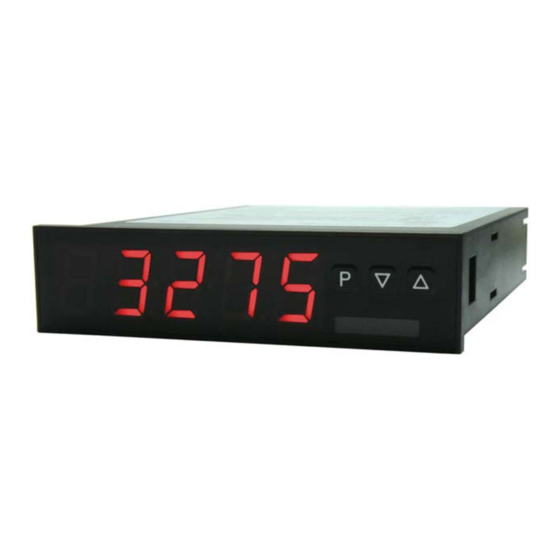
DAG-M3F 5. Operating Principle The panel meter DAG-M3F can evaluate pulses in many different ways and show the result in the 5-digit LED-display. Available options are: frequency coverage with optional filters, summate of pulses or display values via the time, detection of a rotational speed or collection of a position via an incremental encoder. -
Page 6: Assembly
Then use a screwdriver to tighten them another half a turn. CAUTION! The torque should not exceed 0.1 Nm! The dimension symbols can be exchanged before installation via a channel on the side! page 6 DAG-M3F K05/0123... -
Page 7: Electrical Connection
DAG-M3F 7. Electrical Connection Type DAG-M3F80W0R supply 100-240 VAC 50/60Hz, DC ±10% Type DAG-M3F70W0R supply 10-40 VDC galv. isolated, 18-30 VAC 50/60Hz Connection examples: DAG-M3F K05/0123 page 7... - Page 8 DAG-M3F Connection examples: page 8 DAG-M3F K05/0123...
-
Page 9: Function And Operation Description
All adjustments are safed automatically by the device and it changes into operating mode, if no further key operation is done within the next 10 seconds. DAG-M3F K05/0123 page 9... - Page 10 DAG-M3F page 10 DAG-M3F K05/0123...
-
Page 11: Setting Up The Device
9.2 Standard parameterisation: (flat operation level) To parameterize the display, press the [P] key in operating mode for 1 second. The display then changes to the menu level with the first menu item TYPE. DAG-M3F K05/0123 page 11... - Page 12 DAG-M3F page 12 DAG-M3F K05/0123...
- Page 13 DAG-M3F DAG-M3F K05/0123 page 13...
- Page 14 DAG-M3F page 14 DAG-M3F K05/0123...
-
Page 15: Programming Interlock Run
DAG-M3F 9.3 Programming interlock RUN DAG-M3F K05/0123 page 15... -
Page 16: Extended Parameterisation (Professional Operation Level)
DAG-M3F 9.4 Extended parameterisation (Professional operation level) 9.4.1 Signal input parameters page 16 DAG-M3F K05/0123... - Page 17 DAG-M3F DAG-M3F K05/0123 page 17...
- Page 18 DAG-M3F page 18 DAG-M3F K05/0123...
- Page 19 DAG-M3F DAG-M3F K05/0123 page 19...
- Page 20 DAG-M3F 9.4.2 General device parameters page 20 DAG-M3F K05/0123...
- Page 21 DAG-M3F DAG-M3F K05/0123 page 21...
- Page 22 DAG-M3F page 22 DAG-M3F K05/0123...
- Page 23 DAG-M3F DAG-M3F K05/0123 page 23...
- Page 24 DAG-M3F 9.4.3 Safety parameters page 24 DAG-M3F K05/0123...
- Page 25 DAG-M3F 9.4.4 Serial parameters DAG-M3F K05/0123 page 25...
- Page 26 DAG-M3F 9.4.5 Analog output parameters page 26 DAG-M3F K05/0123...
- Page 27 DAG-M3F DAG-M3F K05/0123 page 27...
- Page 28 DAG-M3F 9.4.6 Relay functions page 28 DAG-M3F K05/0123...
- Page 29 DAG-M3F DAG-M3F K05/0123 page 29...
- Page 30 DAG-M3F 9.4.7 Alarm parameters page 30 DAG-M3F K05/0123...
- Page 31 DAG-M3F DAG-M3F K05/0123 page 31...
- Page 32 DAG-M3F 9.4.8 Totaliser (Volume measurement page 32 DAG-M3F K05/0123...
- Page 33 DAG-M3F Description see page 14, menu level RUN DAG-M3F K05/0123 page 33...
-
Page 34: Reset To Factory Settings
With reset, the default values of the program table are loaded and used for subsequent operation. This puts the unit back to the state in which it was supplied. Caution! All application-related data are lost page 34 DAG-M3F K05/0123... -
Page 35: Alarms/Relays
This device has 4 virtual alarms that can monitor one limit value in regard of an undercut or exceedance. Each alarm can be allocated to an optional relay output S1-S2; furthermore, alarms can be controlled by events like e.g. Hold value or min/max-value. DAG-M3F K05/0123 page 35... -
Page 36: Interfaces Rs232 And Rs485
(Twisted-Pair). On each end of the bus segment a termination of the bus lines needs to be connected. This is necessary to ensure a secure data transfer to the bus. For this a resistance (120 Ohm) is interposed between the lines Data B (+) and Data A (–). page 36 DAG-M3F K05/0123... -
Page 37: Programmer Examples
There is a zero point position with a limit switch, that can zero the display if required. Advice: The display starts always on position zero. The parameter dig.in can be found under parameter group –fct – in the extended parameterisation Prof. DAG-M3F K05/0123 page 37... - Page 38 Based on the default settings of the display, the following parameters need to be changed: If the frequency needs to be displayed with a position after decimal point, then a 60 has to be selected as final value for this adjustment. page 38 DAG-M3F K05/0123...
- Page 39 U/min. 0…3600 U/min is preset as rotation speed range of the machine. Calculation of the input frequency Setting up the device Based on the default settings of the device, following parameters need to be changed: DAG-M3F K05/0123 page 39...
-
Page 40: Technical Information
DAG-M3F 14. Technical Information Operating instructions, data sheet, approvals and further information via the QR code on the device or via www.kobold.com 15. Order Codes Operating instructions, data sheet, approvals and further information via the QR code on the device or via www.kobold.com 16. -
Page 41: Safety Advices
Galvanic isolated potentials within one complex need to be placed on a appropriate point (normally earth or machines ground). So, a lower disturbance sensibility against impacted energy can be reached and dangerous potentials, that can occur on long lines or due to faulty wiring, can be avoided. DAG-M3F K05/0123 page 41... -
Page 42: Error Elimination
DAG-M3F 18. Error elimination page 42 DAG-M3F K05/0123... -
Page 43: Disposal
(Cd, Hg, Li or Pb) of the heavy metal that is decisive for the classification as containing pollutants: 1. „Cd" stands for cadmium 2. „Hg" stands for mercury 3. „Pb" stands for lead 4. „Li" stands for lithium Electrical and electronic equipment DAG-M3F K05/0123 page 43... -
Page 44: Eu Declaration Of Conformance
DAG-M3F 20. EU Declaration of Conformance We, KOBOLD Messring GmbH, Hofheim-Ts, Germany, declare under our sole responsibility that the product: Digital Indicator and Controller Model: DAG-M3F to which this declaration relates is in conformity with the standards noted below: EN 61010-1:2010 + A1:2019 + A1:2019/AC:2019...
Need help?
Do you have a question about the DAG-M3F and is the answer not in the manual?
Questions and answers