Keysight Technologies X-Series Manual
Signal analyzer
Hide thumbs
Also See for X-Series:
- Getting started manual (107 pages) ,
- Programming manual (398 pages) ,
- Installation notes (27 pages)
Table of Contents
Advertisement
Quick Links
Advertisement
Table of Contents

Related Manuals for Keysight Technologies X-Series


Summary of Contents for Keysight Technologies X-Series
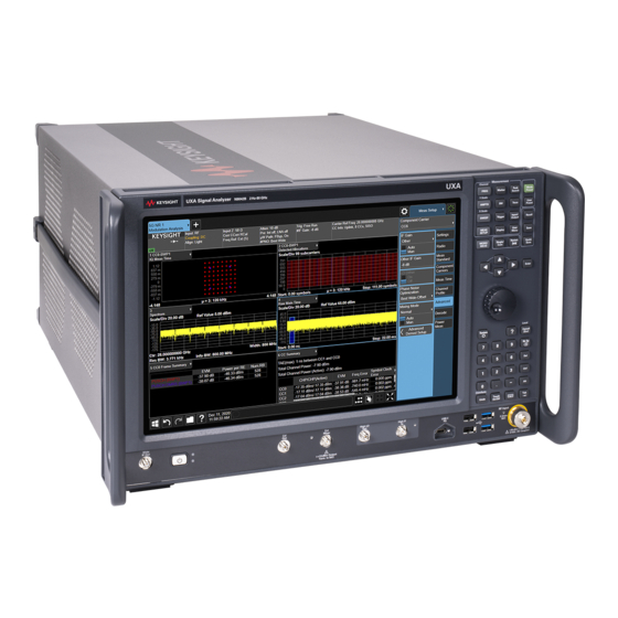
- Page 1 X-Series Signal Analyzer N9042B Cooling Fan Upgrade Option HW2 INSTALLATION NOTE...
- Page 2 The information contained in this document is subject to change without notice. Keysight Technologies makes no warranty of any kind with regard to this material, including but not limited to, the implied warranties of merchantability and fitness for a particular purpose.
- Page 3 Option HW2 – Cooling Fan Upgrade Option HW2 – Cooling Fan Upgrade Products Affected: UXA N9042B To Be Performed By: (X) Keysight Service Center (X) Advanced User ( ) User Estimated Installation Time: 1.5 Hours Estimated Adjustment Time: 0.0 Hours Estimated Verification Time: 1.0 Hours This document provides detailed instructions for the installation of the Cooling Fan upgrade for the...
-
Page 4: Table Of Contents
What You Will Find in this Document What You Will Find in this Document Information......................page 5 Upgrade Contents ......................page 7 Tools Required ......................page 7 Initial Instrument Functionality Check ................ page 7 Option G2H Check......................page 7 Upgrade Instructions.................... -
Page 5: Esd Information
ESD Information ESD Information Protection from Electrostatic Discharge Electrostatic discharge (ESD) can damage or destroy electronic components. All work on electronic assemblies should be performed at a static-safe workstation. Figure 1 shows an example of a static-safe workstation using two types of ESD protection: —... - Page 6 ESD Information Handling of Electronic Components and ESD The possibility of unseen damage caused by ESD is present whenever components are transported, stored, or used. The risk of ESD damage can be greatly reduced by paying close attention to how all components are handled.
-
Page 7: Upgrade Contents
Upgrade Contents Upgrade Contents Table 1-1 Upgrade Contents Part Number Description Quantity Fan Assembly N9041-60070 Dress Cover Assembly This upgrade kits includes a new preassembled fan assembly to replace the existing one, along with a new instrument dress cover to match the new location of the cooling fans. This kit is intended to be used when either an older version of the assembly needs replacing, or when the owner of the instrument has requested to have this newly designed assembly installed to reduce the acoustic noise level of the instrument. -
Page 8: Upgrade Instructions
Upgrade Instructions Upgrade Instructions Hardware Removal Dress Cover Removal 1. Turn the instrument off and disconnect the power cord. 2. Referring to Figure 2, remove the two screws (1) that attach the strap handles (2) from both sides of the instrument and remove the strap handles. Figure 2 Dress Cover Removal 3. - Page 9 Upgrade Instructions Front Panel Removal 6. Referring to Figure 3, remove W1 (1) from the A7 Midplane board (2). Figure 3 Disconnect W1 From A7 Midplane 7. Referring to Figure 4, remove the seven flathead screws (1) from each side of the A1 Front Panel assembly and two flathead screws (2) from the bottom that attach it to the instrument.
- Page 10 Upgrade Instructions 8. Referring to Figure 5, slide the A1 Front Panel assembly aware from the instrument enough to access and remove W2 (1) from the A1A3 Front Panel Daughter board. Figure 5 W2 Access and Removal 9. Set the A1 Front Panel assembly aside. Installation Note N9042-90013...
- Page 11 Upgrade Instructions Old Fan Assembly Removal 10.Referring to Figure 6, remove the two flathead screws (1) and the two panhead screws (2) attaching the rear panel to the fan assembly. Figure 6 Fan Assembly Removal 11.Remove the four flathead screws (3)(4) attaching the top brace and the card cage side brace to the fan assembly.
- Page 12 Upgrade Instructions Figure 7 A7 Midplane Board Fan Connections 16.The old fan assembly can now be removed and discarded. Installation Note N9042-90013...
-
Page 13: Hardware Installation
Upgrade Instructions Hardware Installation Fan Assembly Installation 1. Set the bottom edge of the new fan assembly into place in the instrument with the top tilting outward 2. Referring to Figure 7, connect the two fan power supply connectors to the two lower connectors (1) on the side of the A7 Midplane board 3. - Page 14 Upgrade Instructions 8. Torque all sixteen screws that were installed in steps 4 through 7 to 9 in-lbs. Front Panel Installation 9. Referring to Figure 9, position the A1 Front Panel assembly near the front of the instrument and attach W2 (1) to the A1A3 Front Panel Daughter board. Figure 9 W2 Connection 10.Referring to...
- Page 15 Upgrade Instructions Figure 10 A1 Front Panel Installation 11.Referring to Figure 11, plug W1 (1) back into the A7 Midplane board. Figure 11 W1 Connection to A7 Midplane Board Installation Note N9042-90013...
-
Page 16: Verify Operation
Upgrade Instructions Verify Operation The operation of the new fans should be verified before installing the instrument dress cover. 1. Connect the AC mains to the instrument and turn it on. 2. Verify that both fans are spinning and sucking air into the instrument. 3. -
Page 17: Instrument Button Up
Upgrade Instructions Instrument Button Up Dress Cover Installation 1. Referring to Figure 12, carefully slide the outer cover (5) onto the instrument. Figure 12 Dress Cover Installation 2. Attach the four rear feet (4) using the four panhead screws and washers (3). Torque the screws to 21 in-lbs. -
Page 18: Adjustments And Performance Verification
Adjustments and Performance Verification Adjustments and Performance Verification Manual Procedures Required Front Panel Key Test Front Panel Display Test Front Panel Touch Test Automated Utilities Required None Automated Adjustments Required None Automated Performance Verification Testing Required Residual Response Displayed Average Noise Level Phase Noise 1. - Page 19 This information is subject to change without notice. © Keysight Technologies 2023 Edition 1, January 2023 N9042-90013 www.keysight.com...
Need help?
Do you have a question about the X-Series and is the answer not in the manual?
Questions and answers