Table of Contents
Advertisement
Quick Links
Advertisement
Chapters
Table of Contents

Related Manuals for ETAS XETK-S21.0B


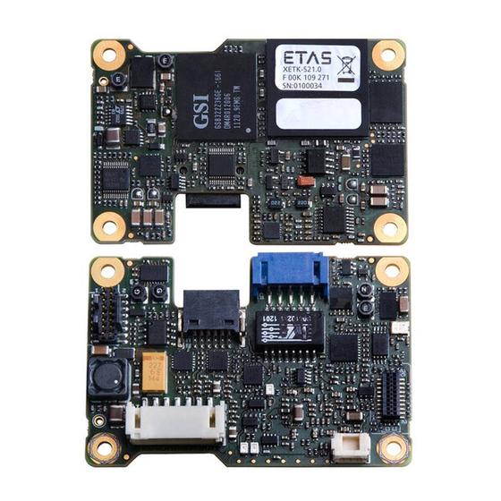
Summary of Contents for ETAS XETK-S21.0B
- Page 1 XETK-S21.0B Emulator Probe for MPC57xx and EMU57xx MCU Family User’s Guide...
- Page 2 The data in this document may not be altered or amended without special noti- fication from ETAS GmbH. ETAS GmbH undertakes no further obligation in rela- tion to this document. The software described in it can only be used if the customer is in possession of a general license agreement or single license.
-
Page 3: Table Of Contents
ECU Voltage Supervisor ........21 XETK-S21.0B - User’s Guide... - Page 4 System Requirements ......... 35 7.1.1 ETAS Compatible Hardware......35 7.1.2 PC with one Ethernet interface .
- Page 5 CBAE200 Adapter Cable ....... . 50 ETAS Module Interface Adapter Cable ......51 8.4.1...
- Page 6 Contents ETAS XETK-S21.0B - User’s Guide...
-
Page 7: About This Manual
Goal definition: any advance information... • Step 1 Any explanation for step 1... • Step 2 Any explanation for step 2... • Step 3 Any explanation for step 3... Any concluding comments... XETK-S21.0B - User’s Guide... -
Page 8: Scope Of Supply
(see chapter "Order- ing Information"). Additional cables and adapters can be obtained separately from ETAS. A list of accessories and their order designation is available in this manual and at the ETAS Home Page. -
Page 9: Basic Safety Notices
• "Declarable Substances" on page 14 • "Use of Open Source Software" on page 14 General Safety Information Please observe the Product Safety Notices ("ETAS Safety Notice") and the follow- ing safety notices to avoid health issues or damage to the device. Note Carefully read the documentation (Product Safety Advice and this User's Guide) that belongs to the product prior to the startup. - Page 10 The product is designed in accordance with state-of-the-art technology and rec- ognized safety rules. The product may be operated only in a technically flawless condition and according to the intended purpose and with regard to safety and XETK-S21.0B - User’s Guide...
- Page 11 Cabling Use exclusively ETAS cables at the connections of the product! Adhere to the maximum permissible cable lengths! Observe the assignment of the cables to the connectors! Detailed information about cabling is located in the ETK User's Guides.
-
Page 12: Identifications On The Product
SN: yyxxxxx Serial number (7-digit) XXXX/YY Product version ZZZZ Year of manufacture ETAS GmbH, Manufacturer's address PO Box 300220, 70442 Stuttgart, Germany Note For symbols and product information one or several adhesive labels can be used. XETK-S21.0B - User’s Guide... -
Page 13: Taking The Product Back And Recycling
CE marking With the CE mark attached to the product or its packaging, ETAS confirms that the product corresponds to the applicable product-specific European Directives. The CE Declaration of Conformity for the product is available upon request. -
Page 14: Declarable Substances
Some products from ETAS GmbH (e.g. modules, boards, cables) use components with substances that are subject to declaration in accordance with the REACH regulation (EU) no.1907/2006. Detailed information is located in the ETAS download center in the customer information "REACH Declaration" (www.etas.com/Reach). This information is continuously being updated. -
Page 15: Introduction
The XETK-S21.0 supports the standard full duplex 100Base-T Ethernet interface and can be connected directly or via ES51x/ES59x/ES600 modules to the PC. No additional ETAS modules are required for the access to the ECU. The XETK-S21.0 can be used for rapid prototyping applications (bypass) as well as for measure- ment and calibration applications. - Page 16 – Direct connection to PC – Open XCP on Ethernet Protocol – Supports a variety of standard applications • “ETK Drivers and Tools” update to support ETAS software tools (INCA, XCT) • Firmware update (programming of the logic device) through HSP software service packs;...
-
Page 17: Hardware Description
This process is Triggered Direct Measurement (TDM) with DISTAB13. The 100 Mbit/s XETK Ethernet interface provides communication with the PC. The power supply for the XETK-S21.0 is provided by a switch mode power sup- ply, to minimize power dissipation. XETK-S21.0B - User’s Guide... -
Page 18: Ecu Interface
• 1 Reset line which allows the XETK to monitor the system reset of the ECU • 5 Debug line interfaces for the communication between the XETK-S21.0 and the microcontroller • 2 ground lines for proper shielding of the ECU interface lines. CON7 CON6 Fig. 4-2 Location of the ECU Interfaces XETK-S21.0B - User’s Guide... -
Page 19: Xetk Ethernet Interface
The XETK Ethernet interface can be directly connected to the PC via CON5 (refer to Fig. 4-3). No additional ETAS module is required for the access to the ECU. The interface is a standard full duplex 100Base-TX Ethernet interface using the XCP protocol. -
Page 20: Debug Interface
The XETK-S21.0 features a JTAG debugging interface connector CON1 (Samtec 16 pin). This connector can be used to attach debug tool (e.g. Lauterbach or PLS debugger). It is recommended to use the ETAS Debug - Adapter (e.g. ETAF11 or AS_ETAF13) to connect the debugger to the XETK. -
Page 21: Power Supply
The XETK-S21.0 provides two opportunities to supply and supervise the ECU RAM standby voltage: 1. The XETK-S21.0 monitors the VDDSBRAM supply on board the XETK. The microcontroller’s standby power supply pin must be connected to the XETK pin VDDSBRAM. XETK-S21.0B - User’s Guide... -
Page 22: Status Leds
Green LED stays on until the calibration and development system downloads data into the calibration data memory. Otherwise switching to the Working Page is not possible. Yellow Flashing Communication active 100 Mbit/s link to calibration system established XETK-S21.0B - User’s Guide... -
Page 23: Data Emulation And Data Measurement
XETK until the microcontroller is powered up and the startup handshake is performed. Serial XETKs use the ETAS two page concept, consisting of both a Reference and a Working page. The Reference Page is located in the ECU flash and can not be modified by a simple write access. -
Page 24: Jtag Interface
ECU for these signals. Additionally, if a pull down resistor is present on the line /TRST, the ECU must use a value no smaller than 10K ohm as shown in Fig. 4-7 on page 24. XETK-S21.0B - User’s Guide... -
Page 25: Trigger Modes: Overview
A configurable period is used for triggering. The time intervals between trigger events are in accordance with the configured timer values. This values and their resolution have to be defined in the XETK’s configuration and/or A2L file. Available settings are: XETK-S21.0B - User’s Guide... -
Page 26: Reset
When waking up the ECU via the CalWakeUp pin, it can be configured if the pin is driven high until the microcontroller core voltage (VDDP) is high or if the pin should be driven high until the start-up handshake between ECU and XETK is complete. XETK-S21.0B - User’s Guide... -
Page 27: Installation
The suitable connectors JST-7 and Samtec-10 (see Fig. 5-2 for additional connec- tor details) should have been populated onto the ECU PCB for adapters ETAI10 and ETAI5/ ETAI6/ ETAI8. ETAI5 or ETAI6 or ETAI8 XETK-S21.0 ETAI10 Fig. 5-1 XETK-S21.0 Connection to the ECU XETK-S21.0B - User’s Guide... -
Page 28: Fig. 5-2 Xetk-S21.0 Connection To The Ecu
Installation ETAS XETK-S21.0 ETAI10 Samtec receptacle TFM-105-02-S-D-P ETAI5 Open Wires ETAI6 JST receptacle B5B-PH-SM4-TB ETAI8 JST receptacle B7B-PH-SM4-TB CON1 CON1 Debugger ETAF11/13 ETAF11/13 Flatcable Fig. 5-2 XETK-S21.0 Connection to the ECU XETK-S21.0B - User’s Guide... -
Page 29: Wiring
Wiring - XETK Ethernet Interface The XETK Ethernet interface can be directly connected to the PC. No additional ETAS module is required for the access to the ECU. Note The XETK Ethernet interface is compatible with the Ethernet interfaces of the ES51x/ES59x/ES600/ES910 module. -
Page 30: Fig. 5-4 Permanent Power Supply Inside Ecu Available
_~ííÉêó Fig. 5-5 Permanent Power Supply inside ECU not available Isolated Power Supply inside ECU The XETK-S21.0 does not require a galvanically isolated power supply. For special applications ETAS offers the isolated power supply ETP2. mçïÉê=pìééäó=`çååÉÅíçê mÉêã~åÉåí=pìééäó= fëçä~íÉÇ=mçïÉê=pìééäó m~Ç=Ñçê=mçïÉê=pìééäó fåéìí... - Page 31 ETAS Installation XETK-S21.0B - User’s Guide...
- Page 32 Installation ETAS XETK-S21.0B - User’s Guide...
-
Page 33: Xetk Configuration
Configuration Parameter The XCT Tool provides support concerning hardware configuration parameters and their possible values. They are described for the different (X)ETK types in the help document of the "(X)ETK Configuration Tool". XETK-S21.0B - User’s Guide... - Page 34 The XCT Tool help window opens. (X)ETK • Choose Reference to User Interface Hardware Configuration Parameters. • Choose the topic XETK-S21.0. The topic XETK-S21.0 contains information about the XETK-S21.0 hardware configuration parameters and their possible values. XETK-S21.0B - User’s Guide...
-
Page 35: Technical Data
• "Allow the computer to turn off this device to save power". 7.1.3 Software Support The configuration instructions for the XETK-S21.0B under INCA and HSP are con- tained in the relevant software documentation. • MPC57xx: Freescale microcontroller device • EMU57xx: STMicroelectronics microcontroller device You need following software versions to support the XETK-S21.0:... - Page 36 V10.7 (DISTAB13) SPC/EMU58NE84 V4.6 V6.4 V10.11 SBB V2.1 HBB V4.5 V6.3 V10.9 (DISTAB13) SPC/EMU58NN84 V4.6 V6.4 V11.2 SBB V2.1 HBB V4.5 V6.3 V11.2 (DISTAB13) Operating the XETK-S21.0 with older software versions is not possible. XETK-S21.0B - User’s Guide...
-
Page 37: Data Emulation And Measurement Memory
RAM if the entire ED RAM is needed for calibration. Configuration Item Characteristics Configuration Project-specific configuration for - different microcontrollers or - memory configurations stored in EEPROM Update Logic devices updated using HSP soft- ware XETK-S21.0B - User’s Guide... -
Page 38: Xetk Ethernet Interface
To ensure successful initialization of the network card of your PC, refer to chap- ter 7.1.2 on page 35 Environmental Conditions Item Characteristics Temperature range (operation) - 40 °C to +110 °C - 40 °F to +230 °F XETK-S21.0B - User’s Guide... -
Page 39: Power Supply
2) if I = 0 mA at pin VDDSBRAM Note The XETK-S21.0 will accept permanent power supply voltage dips down to 3 V, for a maximum duration of 15 ms (for additional details of 3 V low voltage operation, see ISO standard 16750). XETK-S21.0B - User’s Guide... -
Page 40: Test Characteristics
XETK-S21.0. The JTAG wiring to the ECU (ETAI10) must be taken into account additionally. All timings are measured at a reference level of 1.5 V. Output signals are mea- sured with 20 pF to ground and 50 to 1.5 V. 7.8.1 JTAG Timing Diagram XETK-S21.0B - User’s Guide... -
Page 41: Jtag Timing Parameters
7.8.3 Debugger Arbitration Timing Diagram 7.8.4 Debugger Arbitration Timing Parameters Parameter Value [ns] d_tck (Debugger --> XETK) d_tdi (Debugger --> XETK) d_tms (Debugger --> XETK) d_trst (Debugger --> XETK) d_tdo (XETK --> Debugger) XETK-S21.0B - User’s Guide... -
Page 42: Electrical Characteristics
Electrical Characteristics 7.9.1 ECU Interface Characteristics Parameter Symbol Condition Unit CalWakeup Output Voltage CALWAKEUP = 6 - 18 V; - 1 V Batt Batt Batt load 0 - 50 mA VDDP ECU Power Supply Supervision VDDP 2.48 2.58 2.68 Voltage (3.3 V selected) VDDP ... -
Page 43: Ecu Interface Connector Con6
Open Drain FET; I = 0.2 A Dmax Signals not connected to logic on XETK, pass through to debugger 7.9.3 Debugger Interface Connector CON1 TDI, +/-3 /TRST TMS, +/-3 /PORST +/-3 /ESR0 /WDGDIS +/-3 /EVTI XETK-S21.0B - User’s Guide... -
Page 44: Pin Assignment
Debugger event signal (currently unused) Signal Ground JTAG signal /PORST BiDir ECU Reset signal (open drain) for Reset asser- tion and supervision VDDP (Sense) In Sense for Switched power supply of ECU (igni- tion) /ESR0 ECU Reset signal for supervision XETK-S21.0B - User’s Guide... -
Page 45: Interface And Power Supply Connector Con7
ECU Reset signal (open drain) for Reset asser- tion and supervision /TRST JTAG Signal /EVTO Debugger event signal JTAG Signal Signal Ground /EVTI Debugger event signal /BREQ Bus Request to XETK /BGRANT Bus Grant from XETK /ESR0 ECU Reset signal for supervision XETK-S21.0B - User’s Guide... -
Page 46: Mechanical Dimensions
+/- 0.008 Fig. 7-2 XETK-S21.0 Dimensions - Side View Item Dimension Tolerance Dimension Tolerance [Millimeters] [Millimeters] [Inches] [Inches] 3.43 +/- 0.20 0.135 +/- 0.008 1.57 +/- 0.16 0.062 +/- 0.006 5.51 +/- 0.10 0.217 +/- 0.004 XETK-S21.0B - User’s Guide... -
Page 47: Cables And Accessories
XETK. Usable for ECUs with shielded housing. Note The hardware for mounting ECU adapter cables is not included in the cable delivery, they need to be ordered separately. For detailed information on mounting accessories contact ETAS technical support. Product Length Order Number CBAM240.1-0m6... -
Page 48: Cbam271 Adapter Cable
For mounting the cable, cut a PG9 thread into the ECU housing. For thin walled housings use a nut SM-PE 9. Available from Lapp, Order number: 52103210. Product Length Order Number CBAM271.1-0m5 0.5 m F 00K 107 867 XETK-S21.0B - User’s Guide... -
Page 49: Combined Interface And Power Supply Cable
ECU! Note For mounting the cable, cut a PG9 thread into the ECU housing. For thin walled housings use a nut SM-PE 9. Available from Lapp, Order number: 52103210. XETK-S21.0B - User’s Guide... -
Page 50: Pc Interface Cable
CBAE200 Adapter Cable Fig. 8-7 CBAE200 Adapter Cable Cable adapter to connect CBE230 cable to the PC over an RJ45 connector. The CBAE200.2-1m20 supports Gigabit Ethernet. Product Length Order Number CBAE200.2-1m20 1.20 m F 00K 105 760 XETK-S21.0B - User’s Guide... -
Page 51: Etas Module Interface Adapter Cable
Cables and Accessories ETAS Module Interface Adapter Cable 8.4.1 CBE230 Cable Fig. 8-8 CBE230 Cable Gigabit Ethernet connection cable for ETAS devices. IP67 rated Lemo connectors on both sides. Gigabit Ethernet cable with power supply. Product Length Order Number CBE230.1-3 F 00K 105 757 CBE230.1-8... -
Page 52: Power Supply Cables
Cables and Accessories ETAS Power Supply Cables 8.5.1 Cable K70 Fig. 8-10 Power Supply Cable K70 Millimeters Inches 2000 78.74 8.5.2 Cable KA50 Fig. 8-11 Power Supply Cable KA50 Millimeters Inches 7.87 1.97 XETK-S21.0B - User’s Guide... -
Page 53: Ecu Interface Adapters
See Fig. 5-2 on page 28 for details on mating connector to the ETAI5 8.6.2 XETK - ECU Adapter ETAI6 Fig. 8-13 XETK - ECU Adapter ETAI6 Millimeters Inches 100.00 3.94 Note See Fig. 5-2 on page 28 for details on mating connector to the ETAI6 XETK-S21.0B - User’s Guide... -
Page 54: Xetk - Ecu Adapter Etai8
See Fig. 5-2 on page 28 for details on mating connector to the ETAI8 8.6.4 XETK - ECU Adapter ETAI10 Fig. 8-15 XETK - ECU Adapter ETAI10 Millimeters Inches 5.35 Note See Fig. 5-2 on page 28 for details on mating connector to the ETAI10 XETK-S21.0B - User’s Guide... -
Page 55: Debug Adapter Etaf11
• adapt the ECU-ETK connector to the Debugger • adapt the ETK-Debugger connector to the Debugger ETAF11 Flatcable Fig. 8-16 ETAF11 Flatcable ETAF11 Component Placement Fig. 8-17 ETAF11 Component Placement ETAF11 PCB Fig. 8-18 ETAF11 - Mechanical Dimensions and Component Placement XETK-S21.0B - User’s Guide... -
Page 56: Debug Adapter As_Etaf13.0
XETK-S21.0 debug connector (16 pin Samtec). The board and the cable are deliv- ered as one item. AS_ETAF13.0 Debug Adapter AS_ETAF13.0 Top AS_ETAF13.0 Bottom (Plugs into Debugger) (Plugs into Ribbon cable) 13mm AS_ETAF13.0 Debugger Adapter Board 3D view AS_ETAF13.0 Ribbon Cable 76.2mm Fig. 8-19 AS_ETAF13.0 Debug Adapter XETK-S21.0B - User’s Guide... -
Page 57: Water Proof Case Etks_C3
For mounting the XETK-S21.0 on top of ECUs, an external case is available. It is small, robust and water proof (IP65). Fig. 8-20 ETKS_C3 Top View Fig. 8-21 ETKS_C3 Bottom View Fig. 8-22 ETKS_C3 Side View XETK-S21.0B - User’s Guide... - Page 58 Cables and Accessories ETAS XETK-S21.0B - User’s Guide...
-
Page 59: Ordering Information
Debug Adapter from Debugger to ETK ETAF11 F00K 107 682 Debug Adapter from Debugger to XETK- AS_ETAF13.0 F00K 110 451 Power Supply Order Name Short Name Order Number Isolated Power Supply Interface for XETK ETP2 F 00K 104 010 XETK-S21.0B - User’s Guide... -
Page 60: Cables
Ordering Information ETAS Cables Please contact your local ETAS representative for further cable information. Note The cables showed in chapter "Cables and Accessories" on page 47 are not included in the XETK-S21.0 delivery. 9.5.1 ECU Adapter Cables Note The hardware for mounting ECU adapter cable CBAM240.1 is not included in the cable delivery, they need to be ordered separately. -
Page 61: Ethernet Cables
Y 261 A24 942 Lemo 0B FGG - open wires (2fc-1c), 2 m XETK Power Supply Cable for External Sup- KA50 F 00K 000 940 ply, with Filter Coil, Lemo 0B EGG - open wire (2fc-1c), 0m2 XETK-S21.0B - User’s Guide... -
Page 62: Waterproof Case
Ordering Information ETAS Waterproof Case Order Name Short Name Order Number Water proof case, designed for ETK-S4.x, ETKS_C3 F 00K 107 683 ETK-S6.x and ETK-S2x XETK-S21.0B - User’s Guide... -
Page 63: Etas Contact Addresses
Germany WWW: www.etas.com ETAS Subsidiaries and Technical Support For details of your local sales office as well as your local technical support team and product hotlines, take a look at the ETAS website: ETAS subsidiaries WWW: www.etas.com/en/contact.php ETAS technical support WWW: www.etas.com/en/hotlines.php... - Page 64 ETAS Contact Addresses ETAS XETK-S21.0B - User’s Guide...
-
Page 65: Figures
CBAM270 Cable (0.7 m length)..............49 Fig. 8-6 CBE200-3 Cable ..................50 Fig. 8-7 CBAE200 Adapter Cable................50 Fig. 8-8 CBE230 Cable .................... 51 Fig. 8-9 CBAE330 Adapter Cable................51 Fig. 8-10 Power Supply Cable K70................52 XETK-S21.0B - User’s Guide... - Page 66 Fig. 8-18 ETAF11 - Mechanical Dimensions and Component Placement..... 55 Fig. 8-19 AS_ETAF13.0 Debug Adapter ..............56 Fig. 8-20 ETKS_C3 Top View ..................57 Fig. 8-21 ETKS_C3 Bottom View................57 Fig. 8-22 ETKS_C3 Side View..................57 XETK-S21.0B - User’s Guide...
-
Page 67: Index
Ethernet Interface 19 CBAM270 49 ETK Configuration 33 CBAM271 48 ETKS_C3 57 CBE200-3 50 CBE230 51 Interface 47 Features 15 Power Supply 52 Configuration 37 Parameter 33 Hardware Description 17 DAP Interface 24 Identifications on the product 12 XETK-S21.0B - User’s Guide... - Page 68 REACH regulation (EU) 14 Recycling 13 Reset 26 RoHS conformity China 13 European Union 13 Safety notices Identification 7 Safety precautions 9 Scope of supply 8 Software Support 35 Status LED 22 System Requirements 35 Test Characteristics 40 XETK-S21.0B - User’s Guide...
Need help?
Do you have a question about the XETK-S21.0B and is the answer not in the manual?
Questions and answers