Table of Contents
Advertisement
Quick Links
Stand-alone HF Motion Sensor
HMW24
Daylight Harvest for Independent DALI
Mechanical Structure
70mm
4
3
1
Infrared receiver
Lens
2
Note:We recommend the mounting distance between sensor to sensor should be more than 2m to prevent sensors
from false-triggering.
Technical Data
Input Characteristics
Model No.
Mains voltage
Stand-by power
Switched power
Warming-up
Safety and EMC
EMC standard (EMC)
Safety standard (LVD)
Radio Equipment (RED)
Certi cation
Subject to change without notice.
HF
Photocell
LED indicator
(1) Sensor inset
(2) Lens pluggable
(3) Protection cover (covers the
high-voltage terminals).
(4) Ceiling (drill hole
HMW24
220~240VAC 50/60Hz
<0.5W
Max. 20pcs devices, 40mA
20s
EN55015, EN61000
EN60669, AS/NZS60669
EN300440, EN301489,
EN62479
Semko, CB, CE, EMC, RED, RCM
64.7
Ø
70mm).
Rotary Switch
Sensor Data
Model No.
Sensor principle
Operation frequency
Transmission power
Detection angle
Environment
Operation temperature
IP rating
Edition: 26 Feb. 2020
Intelligent
One-Key
Photocell
Commissioning
TX
0
6
Ambient daylight
synchronization
Programing
control
6
HMW24
High Frequency (microwave)
5.8GHz +/- 75MHz
<0.2mW
Max. ( O x H) 12m x 6m
O
360
Ta: -20
O
C ~ +50
IP20
RED
Ver. A0
threshold
O
C
IP20
Page 1/6
Advertisement
Table of Contents

Subscribe to Our Youtube Channel
Related Manuals for Hytronik HMW24


Summary of Contents for Hytronik HMW24
- Page 1 Stand-alone HF Motion Sensor HMW24 Daylight Harvest for Independent DALI Mechanical Structure 70mm 64.7 Photocell LED indicator Infrared receiver (1) Sensor inset Rotary switch preset (2) Lens pluggable Intelligent One-Key Photocell Commissioning (3) Protection cover (covers the Detection Pattern high-voltage terminals).
- Page 2 Functions and Features Daylight Harvest Light will not switch on The light switches on The light turns on at full or dims to maintain the lux level. The light output when natural light is automatically with regulates accroding to the level of natural light available. suf cient, even there is presence when natural motion detected.
- Page 3 Synchronisation Function By connecting the “SYNC” terminals in parallel (see wiring diagram), no matter which sensor detects motion, all HMW24 in the group will turn on the lights when surrounding natural light is below the daylight threshold. The detection area could be widely enlarged in this way.
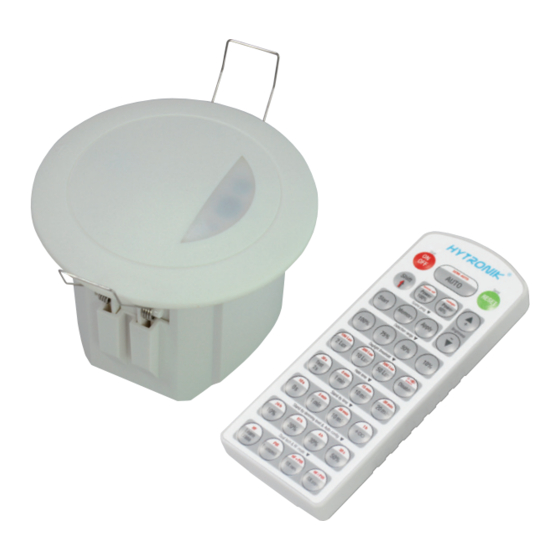
- Page 4 Scene program - 1-key commissioning 1. Press button “Start” to program. 2. Select the buttons in “Detection range”, “Daylight threshold”, “Hold-time”, “Stand-by time”, “Stand-by dimming level” to set all parameters. 3. Press button “Memory” to save all the settings programmed in the remote control. 4.
- Page 5 LED Driver LED Driver LED _ DALI+ DALI+ DALI DALI HMW24 HMW24 DALI DALI 1. 200 metres (total) max. for 1mm〔 CSA (Ta = 50メ) 2. 300 metres (total) max. for 1.5mm〔 CSA (Ta = 50メ) Detection Pattern Subject to change without notice.
- Page 6 Additional Information / Documents 1. Regarding precautions for microwave sensor installation and operation, please kindly refer to www.hytronik.com/download ->knowledge ->Microwave Sensors - Precautions for Product Installation and Operation 2. Regarding Hytronik standard guarantee policy, please refer to www.hytronik.com/download ->knowledge ->Hytronik Standard Guarantee Policy Subject to change without notice.
Need help?
Do you have a question about the HMW24 and is the answer not in the manual?
Questions and answers