Advertisement
Quick Links
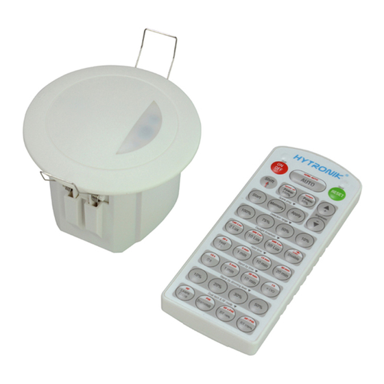
FLUSH MOUNT MICROWAVE DALI SENSOR HMW25
1. Technical Specifications
Product type
Independent microwave DALI sensor (tri-level control)
Operating voltage
220~240VAC 50/60Hz
Switched power
Max.20pcs devices Max.40mA
Power consumption
< 0.5W
o
Detection angle
360
Detection area (Max.)*
Installation Height : 6m
Detection Range (Ø) :12m
Detection range
10% / 50% / 75% / 100%
Hold time
2s / 30s / 1min / 5min / 10min / 15min / 20min / 30min
Stand-by time
0s / 10s / 1min / 5min / 10min / 30min / 1h / +
Stand-by dimming level
10% / 20% / 30% / 50%
Daylight threshold
2 ~ 500Lux, Disable
Warming up time
20s
o
Operating temperature
-20
C ~ +50
Note:We recommend the mounting distance between sensor to sensor
should be more than 2m to prevent sensors from false-triggering.
3. Rotary Switch Settings
A rotary switch is built inside the sensor for
scene selection / fast programming. Total
16 channels available:
Detection
Hold
Channel
range
time
0
100%
5s
1
100%
1min
2
100%
5min
3
100%
5min
4
100%
5min
5
100%
5min
6
100%
5min
7
100%
10min
8
100%
10min
9
100%
10min
A
100%
10min
B
75%
10min
C
50%
10min
D
100%
30min
E
100%
30min
F
100%
5s
Note: settings can also be changed by remote control HRC-11. The last action controls.
4. Functions
4.1 Tri-level Control (Corridor Function)
Hytronik builds this function inside the motion sensor to achieve tri-level control, for some areas require a
light change notice before switch-off.
It offers 3 levels of light: 100%-->dimmed light-->off; and 2 periods of selectable waiting time: motion
hold-time and stand-by period; Selectable daylight threshold and freedom of detection area.
4.2 Synchronization Function
By connecting the "SYNC" terminals in parallel (see wiring diagram), no matter which sensor detects
motion, all HMW25 in the group will turn on the lights when surrounding natural light is below the daylight
threshold. The sensor module is shared and the detection area could be widely enlarged in this way.
Installation and Instruction Manual
o
C
Rotary switch preset (Please
see the location in 2. Installation)
Stand-by
Stand-by
time
dimming level
10s
10%
5min
10%
10min
10%
30min
10%
0s
Disable
+∞
10%
+∞
30%
10min
10%
30min
10%
+∞
10%
+∞
30%
+∞
10%
+∞
10%
+∞
10%
+∞
30%
10s
10%
2. Installation
Warnings:
1. Installation of the sensor involves connecting it to the mains supply. This work must be
carried out by a specialist in accordance with electrotechnical regulations.
2. Disconnect supply before installing.
Infrared receiver
Rotary switch preset
Daylight
Lens
threshold
Disable
2Lux
10Lux
30Lux
4.3 Lux Off Function
10Lux
The built-in daylight sensor can read ambient natural light and switch off the fixture automatically
30Lux
whenever artificial light is unneeded (natural light lux level exceeds daylight threshold).
Disable
Note: if the stand-by time is preset at "+∞", the fixture never switches off even when natural light
2Lux
is sufficient.
10Lux
30Lux
Disable
4.4 Semi-auto Function (Absence Detection)
30Lux
The motion sensor is employed, but only activated on the manual press of the push switch,
10Lux
light keeps on in the presence, and dims down in the absence, and eventually switches off
50Lux
automatically in the long absence.
Disable
2Lux
4.5 Manual Override
With the help of push-switch, this sensor maybe over-ridden by the end-users to switch on/off
the lights manually, or adjust the light brightness during motion hold-time. This makes the
product more user-friendly and offers more options to fit for extra-ordinary demands.
* Short push (<1s): on/off function;
ON → OFF: the light turns off immediately and cannot be lighten for a certain time (equals
to hold time preset) even there is movement is detected. After this period, the sensor goes
back to auto sensor mode.
OFF → ON: the light turns on 100% and goes to auto sensor mode, even when ambient
Lux level exceeds the daylight threshold.
* Long push (>1s): adjust the maximum brightness (between 10% and 100%) during
Note: end-user can choose either function 4.4 or 4.5 for application. Default function is 4.5.
70mm
4
3
Photocell
1
LED indicator
(1) Sensor inset
(2) Lens pluggable
(3) Protection cover (covers the
high-voltage terminals, and leaves
the DALI terminals exposed).
(4) Ceiling (drill hole O 70mm).
2
hold-time. Both the settings on DIP switch and manual override can
overwrite each other, the last adjustment remains in memory.
64.7
HMW25-20181218-A1
Advertisement

Subscribe to Our Youtube Channel
Related Manuals for Hytronik HMW25


Summary of Contents for Hytronik HMW25
- Page 1 By connecting the “SYNC” terminals in parallel (see wiring diagram), no matter which sensor detects motion, all HMW25 in the group will turn on the lights when surrounding natural light is below the daylight threshold. The sensor module is shared and the detection area could be widely enlarged in this way.
- Page 2 The fixture is on when it should not Adjust zone, change installation site expelled from fans, open windows Hytronik Industrial Ltd. | www.hytronik.com 3rd Floor, block C, complex building, 155#, Bai'gang road south, Bai'gang village, Xiao Jin Kou town, Huicheng district, Huizhou 516023...
Need help?
Do you have a question about the HMW25 and is the answer not in the manual?
Questions and answers