Advertisement
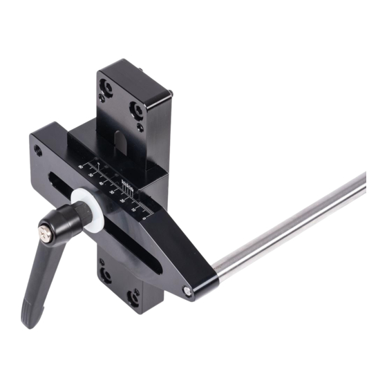
SUPPORT BAR
WITH DUAL AXIS
ADJUSTMENT
Terminology of the Support Bar
Support Bar
Left
Front
These are the striations,
we call them sharpening lines
Bar
Platen
Up
Back
Right
Down
1
Grub screw A
A
Grub screw C
Grub screw D
The 'RED' circles in figure (A) shows the
positions of the grub screws used to adjust
the support bar, to the side of the frame. The
'GREEN' circles in figure (B) shows the
position of the Hex head screws used to fix
the support bar to the side of the linisher.
2
Setting the Jig
Loosen the two studs
Bar
Code 103738
Original Instructions
Grub screw B
B
Continues Over...
Advertisement
Table of Contents

Subscribe to Our Youtube Channel
Related Manuals for Axminster PROFESSIONAL 103738


Summary of Contents for Axminster PROFESSIONAL 103738
- Page 1 Code 103738 Original Instructions Grub screw B Grub screw A SUPPORT BAR WITH DUAL AXIS ADJUSTMENT Grub screw C Terminology of the Support Bar Grub screw D These are the striations, we call them sharpening lines The ‘RED’ circles in figure (A) shows the Support Bar positions of the grub screws used to adjust the support bar, to the side of the frame.
- Page 2 Platen Steel frame 0.5 to 1mm Clearance Loosen the two threaded studs holding the platen. Adjust the platen so it projects out from the steel frame of about 0.5 to 1mm. Tighten the studs to secure the platen in place. Setting the Bar to the Platen Method One Method Two...
Need help?
Do you have a question about the PROFESSIONAL 103738 and is the answer not in the manual?
Questions and answers