
Subscribe to Our Youtube Channel
Related Manuals for BCM MX6210N


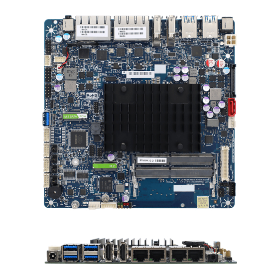
Summary of Contents for BCM MX6210N
- Page 1 MX6210N/MX6412J Intel® Celeron N6210/J6412 SoC Mini-ITX Motherboard User’s Manual Edition 1.02 – December, 2021...
- Page 2 Copyright Notice Copyright 2020 BCM Advanced Research, ALL RIGHTS RESERVED. No part of this document may be reproduced, copied, translated, or transmitted in any form or by any means, electronic or mechanical, for any purpose, without the prior written permission of the original manufacturer.
- Page 3 Disclaimer BCM Advanced Research reserves the right to make changes, without notice, to any product, including circuits and/or software described or contained in this manual in order to improve design and/or performance. BCM Advanced Research assumes no responsibility or liability for...
- Page 4 Manual Objectives This manual describes in detail the BCM MX6210N and MX6412J Main board. We strongly recommend that you study this manual carefully before attempting to interface with this mainboard or change the standard configurations. Whilst all the necessary information is available in this manual we would recommend that unless you are confident, you contact your supplier for guidance.
-
Page 5: Table Of Contents
MX6210N/MX6412J User’s Manual CONTENTS Thin Mini-ITX Board Features ..................8 1. Hardware Specification ................... 12 1.1 HW Design ......................12 1.1.1 Block Diagram ................... 12 1.1.2 Placement - Top ..................13 1.1.3 Placement - Bottom ................... 14 1.1.4 Placement – Rear IO ................. 14 1.1.5 Silkscreen and Label Definition .............. - Page 6 MX6210N/MX6412J User’s Manual 2.5.1 COM Power Jumper Setting ..............34 2.5.2 CMOS Jumper Setting ................35 2.5.3 Backlight Power Jumper Setting ............... 35 2.5.4 LCD Power Jumper Setting ..............36 2.6 Power Management ................... 37 1 Main Page ......................... 39 2 Advanced Page ......................
- Page 7 MX6210N/MX6412J User’s Manual 6 Save & Exit Page ...................... 82 7 Recovery Page (Active for 4.3 Secure Flash Update only) ........83...
-
Page 8: Thin Mini-Itx Board Features
MX6210N/MX6412J User’s Manual Thin Mini-ITX Board Features This chapter briefly describes the features of Thin Mini-ITX Board MX6210N and MX6412J. Below to summarize the major features of the Desktop Board. Feature Summary : MX6210N and MX6412J F ABLE EATURES General SPEC Processor Intel®... - Page 9 MX6210N/MX6412J User’s Manual Type PCI Express Gigabit Ethernet Ethernet 2 Intel® i225-LM (HSIO LANE #3) Type PCI Express Gigabit Ethernet Ethernet 3 Intel® i211-AT (HSIO LANE #4) Type PCI Express Gigabit Ethernet Ethernet 4 Intel® i211-AT (HSIO LANE #5) Type...
- Page 10 MX6210N/MX6412J User’s Manual DC output: 5V 1 x SPI Header (2x4 2.0mm Header) eSPI 1 x eSPI Header (2x5 2.0mm Header) SATA 1 x SATA III Connectors (Red) SATA Power 1 x 15 pin SATA Power Connector Front Audio 1 x Front Audio Header (2x5 2.54mm Pitch) Front Panel 1 x Front Panel Header (2x5 2.54mm Pitch)
- Page 11 MX6210N/MX6412J User’s Manual Temperature -10 C to 60 C Humidity 5% to 85% non-condensing Accessories SATA Signal 1 x SATA Signal Cable SATA Power 1 x SATA Power Cable I/O Shield 1 x Full Size I/O Shield 1 x Half Size I/O Shield...
-
Page 12: Hardware Specification
MX6210N/MX6412J User’s Manual 1. Hardware Specification HW Design 1.1.1 Block Diagram... -
Page 13: Placement - Top
MX6210N/MX6412J User’s Manual 1.1.2 Placement - Top T1 HDR: Front Audio JUMP: COM4 PWR SET T2 HDR: I2C Buzzer T3 HDR: INT_SPK1 Socket / IC: BIOS (MP is no socket) T4 HDR: Battery HDR: eSPI T5 HDR: Front USB2x2 HDR: SPI... -
Page 14: Placement - Bottom
MX6210N/MX6412J User’s Manual T11 Socket: M2 Key-M Socket:DIMM1 T12 CONN: USB3.0 Jumper: LCD_PWR T13 HDR: COM1 Jumper: PNL PWR T14 HDR: COM2 HDR: BACK Light PWR T15 JUMP: COM1 PWR SET CONN: LVDS T16 JUMP: COM2 PWR SET HDR: CPU FAN... -
Page 15: Silkscreen And Label Definition
MX6210N/MX6412J User’s Manual 1.1.5 Silkscreen and Label Definition PWA# Table PWA# Stage Note PVT/MVT Production Release ECR/Rework ECR/Rework ECR with PCB change CE, FCC, and RoHS Logo PWB# Table PWB# Stage Note... - Page 16 6th and 7th digits = Year (06), 8th and 9th digits = Week (46 = 46th week of that year), 10th = BCM internal control code, contact Wing for details. 11th - 15th digits = Serial Number (start with 00001).
-
Page 17: Product Specification
MX6210N/MX6412J User’s Manual LOM MAC Address Label Product Specification 2.1 Elkhart Lake Processor Spec CPU/SOC parts spec Intel® Celeron® Processor N6210 spec Intel® Pentium® Processor J6412 spec 2.2 System Memory- 2ea DDR4 SO-DIMM EHL memory controller can support DDR4 technologies. The system supports memory configuration 1x64 DDR4 and 2x64 DDR4. -
Page 18: Onboard Graphics
MX6210N/MX6412J User’s Manual 2.3 Onboard Graphics Board must support all integrated graphics features supported by the processor through the PCH (including but not limited to DirectX, HD/Blu-ray video hardware decoding, PAVP-Lite and HDCP). Support 3 Display pipes, simultaneous multi-streaming on all three display pipes (1x Internal and 2x External Displays) Supports Intel®... - Page 19 MX6210N/MX6412J User’s Manual Supports Audio on HDMI • LVDS feature: eDP to LVDS bridge IC: Parade PS8625QFN56GTR Enables the use of LVDS display panels with DisplayPort or eDP™ video Source devices ™ Single link or dual link LVDS output, clock speed up to 135MHz ...
-
Page 20: Connector Pinout & Indicator Definition
MX6210N/MX6412J User’s Manual Add GP_D19_TGPIO43_LVDS_CBL_L_DET_N to support LVDS cable detection from Pin 8 & Pin 26 Connector: TF-CON;LVDS,SBU,20Pin*2,1.25mm,MA,ST,Gold Flash,TWO SIDE,Nature,PA6T Joint Tech Electronic Industrial Co.,Ltd. A1252WV-SF-2X20PD01 XIAN YI INTERNATIONAL CO., LTD W2631-40P-R3211 2.4 Connector Pinout & Indicator Definition 2.4.1 Panel Backlight Header... -
Page 21: Edp (Optional)
MX6210N/MX6412J User’s Manual 2.4.2 eDP (Optional) Connector: TF-CON;SBU,40Pin,0.5mm,FM,R/A,Gold Flash,WHITE ACES ELECTRONIC CO.,LTD 88341-4001 2.4.3 M.2 M Key & E Key Expansion Slot Slot Configuration Electrical Physical Connector Color M2_KE1 M.2 key E socket M.2 Key E socket Black M2_KM1 M.2 key M socket M.2 key M socket... - Page 22 MX6210N/MX6412J User’s Manual Function Function DAS/DSS#_IO/LED1#_I_0/3_3V PERN1 PERP1 PERT1 PERP1 DEVSLP_O PERN0 / SATA B+ PERP0 / SATA B- PETN0 / SATA A- PETP0 / SATA A+ PERST#_O_0/3_3V CLKREQ#_IO_0/3_3V REFCLKN REFCLKP PEDET_NC_PCIE/GND_SATA...
-
Page 23: Usb 3.0 Port
MX6210N/MX6412J User’s Manual 2.4.4 USB 3.0 Port 4ea USB 3.0: dual USB3.0 port x2 connector USB3.0 bus control by USB3.0 Gen1 hub ( Genesys® GL3523 USB2.0 bus control by EHL SOC USB3.0 Internal – Type A 1ea USB 3.0 Type-A connector USB3.0 /USB2.0 bus control by EHL SOC... -
Page 24: Sata Power - 15Pin Standard
MX6210N/MX6412J User’s Manual Pin Signal Pin Signal +5V DC +5V DC Data (negative) Data (negative) Data (positive) Data (positive) Ground Ground Key (no pin) No Connect TF-CON;HDR,SBU,5Pin*2,-P9,MA,2.54mm,BLACK,ST,Gold Flash,PA6T(Nylon 6T),NO P9,DIP Joint Tech A2546WV-2X05PR6BG0NQ9G GRAND-TEK HPH-212050-006 SUPERIOR TECH PHED-DS010G1ABONA-N012 2.4.6 SATA Power – 15pin Standard Board must provide internal SATA power connector in order to power internal SATA devices. -
Page 25: I211 And I215Lm Lan Indicator
MX6210N/MX6412J User’s Manual Name Color Description +3.3VDC Orange +3.3 VDC +3.3VDC Orange +3.3 VDC +3.3VDC/ DevSleep Black Ground Black Ground Black Ground +5VDC +5 VDC +5VDC +5 VDC +5VDC +5 VDC Black Ground Black Black Ground +12VDC Yellow +12 VDC... - Page 26 MX6210N/MX6412J User’s Manual or LAN disable LAN link is established or Link Green LAN port disable Link Green blinking LAN activity occurring 10/100 M b/s data rate Speed or LAN disable Speed Green 2500 M b/s data rate 1000 M b/s data rate...
-
Page 27: Audio Combo Jack
MX6210N/MX6412J User’s Manual 2.4.8 Audio Combo Jack Codec driver cannot support Headset type auto detection from iPhone-type and Nokia-type parts Here is jumper setting guide to support iPhone-type or Nokia-type parts JMIC1 Jumper setting iPhone-type headset CITA CITA (1-2) (3-4) -
Page 28: Front I/O Header
MX6210N/MX6412J User’s Manual 2.4.9 Front I/O Header Front I/O header 5P*2: MIC + Line out Front panel audio header must be 2x5, 2.54mm pitch, colored BLACK and keyed at pin 8 TF-CON;HDR,SBU,5Pin*2,-P8,MA,2.54mm,BLACK,ST,Gold Flash,PA6T(Nylon 6T) SUPERIOR TECH CO.,LTD. PHED-DS010G1ABONA-N020 Aquatech Corporation YNK12030-HPH-212050-002 2.4.10 Speaker Header... -
Page 29: Cpu & Sys Fan Header
MX6210N/MX6412J User’s Manual COM3_P9_40mils RI (Ring Indicator) 10 Key Key (no pin) COM3, COM4 : 2 x RS232/422/485 Port (with 5V/12V/RI) Signal Signal RS232 RS485 RS422 RS232 RS485 RS422 1 DCD (Data Carrier Detect) R(A) / T(A) TX(B) 2 RXD# (Receive Data) -
Page 30: Front Panel Header
MX6210N/MX6412J User’s Manual 2.4.13 Front Panel Header Pin Signal Name Description Signal Name Description HDD_POWER_LED Pull-up resistor (750 ) to +5V POWER_LED_MAIN [Out] Front panel LED (main color) HDD_LED# [Out] Hard disk activity LED POWER_LED_ALT [Out] Front panel LED (alt color) - Page 31 MX6210N/MX6412J User’s Manual pin2 link pin2 SPI_CS0_R_N pin3 link pin3 SPI0_CLK_FLSH pin4 link pin4 SPI0_IO1_MISO pin5 link pin5 MISO SPI0_IO0_MOSI pin6 link pin6 MOSI SPI0_IO3_HOLD_N pin7 link pin8 I/O3 SPI0_IO2_WP_N Step6: Run “program BIOS code” at SF100/SF600 tool J_SPI1 SPI header pinout:...
-
Page 32: Espi Header
MX6210N/MX6412J User’s Manual J_SPI1 3VSB_SPI SPI_CS0_R_N SPI0_CLK_FLSH SPI0_IO1_MISO_R SPI0_IO0_MOSI_R SPI0_IO3_HOLD_N SPI0_IO2_WP_N 2.0mm 4Pin*2 SF600 SPI NOR Flash Wp/DQ2 signal is optional Function Function MISO/DQ1 Hold/DQ3 Wp/DQ2 MOSI/DQ0 Reset 2.4.15 eSPI Header J_eSPI1 P80H_eSPI_IO0 3VSB P80H_eSPI_IO1 P80H_eSPI_CLKIN P80H_eSPI_IO2 P80H_eSPI_RST0_N R 0 B # 5 3... -
Page 33: I2C Header
MX6210N/MX6412J User’s Manual 2.4.16 I2C Header Function Pin Pin Function V_I2C_3P3V I2C_RST_N_3P3V 3P3V_I2C2_SCL 1P8V_I2C5_SCL 3P3V_I2C2_SDA 1P8V_I2C5_SDA I2C_INT_N_3P3V TF-CON;HDR,SBU,4Pin*2,4 Walls,MA,2.0mm,BEIGE,ST,Gold Flash Joint Tech A2004WV-2X04PY21 2.4.17 I2S Header Function V_I2S_PW HDR_I2S_TXD HDR_I2S_SCLK HDR_I2S_SFRM HDR_I2S_RXD TF-CON;HDR,SBU,6Pin,4 Walls,MA,2.0mm,BEIGE,ST,TIN, Joint Tech A2001WV-06PR4NT1N05G 2.4.18 GPIO Header... -
Page 34: Dc-In Connector
MX6210N/MX6412J User’s Manual TF-CON;HDR,SBU,5Pin*2,MA,2.0mm,BLACK,ST,Gold Flash,PA6T(Nylon 6T) Joint Tech A2016WV-2X05P6T ACES 60476-010T1-001 2.4.19 DC-in Connector 12V – 24V Wide Range DC-In DC_JACK1 and PW_ATX4P_1 are optional to support DC input power PW_ATX4P_1 is Mini-Fit Jr 4 Pin DC-In Connector VIN_12V_24V DC_JACK1... -
Page 35: Cmos Jumper Setting
MX6210N/MX6412J User’s Manual Support RI signal (Default) JPCOM_1/JPCOM_2/JPCOM_3/JPCOM_4 V_12P NRI1 COM1_P9 V+5P 2.5.2 CMOS Jumper Setting Pins 3&2: Jumper position for CMOS Clear Signal Name SRTC_RTEST_N 2.5.3 Backlight Power Jumper Setting Pin Signal Description... -
Page 36: Lcd Power Jumper Setting
MX6210N/MX6412J User’s Manual 1 PNL_BL_5V 5V option 2 BKLT_PWR Send voltage to connector 3 PNL_BL_12V 12V option 2.5.4 LCD Power Jumper Setting Pin Signal Description 1 Key No pin 2 5V 5V option (default) 3 8v~24V Vin option same as DC-IN power rail... -
Page 37: Power Management
MX6210N/MX6412J User’s Manual 2.6 Power Management Wake-Up Event From ACPI State Comments Power button S3, S4, S5, deep S5/S4 Deep sleep doesn’t support Deep S3 function Doesn’t support “S5/S4 WOL disable” and RTC alarm S3, S4, S5 “Deep power enable mode at S4/S5”... - Page 38 MX6210N/MX6412J User’s Manual MX6210N & MX6412J BIOS SETUP SPEC...
-
Page 39: Main Page
MX6210N/MX6412J User’s Manual 1 Main Page Main Advanced EventLogs Security Boot Save & Exit Item help BIOS Information BIOS Vendor American Megatrends Core Version 5.19 Compliancy UEFI 2.7 ; PI 1.6 BIOS Version MX6211N (71821) BIOS V0.04 Build Date 03/30/2021... - Page 40 MX6210N/MX6412J User’s Manual Comment This field is not selectable. There is no help text associated with it. Field Name Processor Information Value Display the installed CPU brand. Comment This field is not selectable. There is no help text associated with it.
-
Page 41: Advanced Page
MX6210N/MX6412J User’s Manual 2 Advanced Page Main Advanced EventLogs Security Boot Save & Exit Item help ►Onboard Device ►CPU Configuration ►PCH-FW Configuration ►Trusted Computing ►NCT6126D Super IO Configuration ►Hardware Monitor ►S5 RTC Wake Settings ►Network Stack Configuration →←: Select Screen ►NVMe Configuration... -
Page 42: Onboard Device
MX6210N/MX6412J User’s Manual Field Name Network Stack Configuration Help Network Stack Settings. Comment Press Enter when selected to go into the associated Sub-Menu. NVMe Configuration Field Name Help NVMe Device Options Settings Comment Press Enter when selected to go into the associated Sub-Menu. - Page 43 MX6210N/MX6412J User’s Manual Help Select DVMT 5.0 Pre-Allocated (Fixed) Graphics Memory size used by the Internal Graphics Device. DVMT Total Gfx Mem Field Name Default Value [256M] Possible Value 128M 256M Help Select DVMT5.0 Total Graphic Memory size used by the Internal Graphics Device.
-
Page 44: Cpu Configuration
MX6210N/MX6412J User’s Manual Help Select LCD panel used by Internal Graphics Device by selecting the appropriate setup item. Field Name Dual Mode USB3.0 Port Default Value [USB Host Mode] Possible Value USB Host Mode USB Device Mode Help Select USB Operation Mode. - Page 45 MX6210N/MX6412J User’s Manual Default Value Displays the CPU Speed Comment This field is not selectable. There is no help text associated with it. Field Name L1 Data Cache Default Value L1 Data Cache Size Comment This field is not selectable. There is no help text associated with it.
-
Page 46: Pch-Fw Configuration
MX6210N/MX6412J User’s Manual PCH-FW Configuration Main Advanced EventLogs Security Boot Save & Exit Item help ME Firmware Version 15.40.10.2204 ME Firmware Mode Normal Mode ME Firmware SKU Consumer SKU ME Firmware Status 1 0x90000255 ME Firmware Status 2 0x8B100106 ME State [Enabled] →←: Select Screen... -
Page 47: Firmware Update Configuration
MX6210N/MX6412J User’s Manual Help When Disabled ME will be put into ME Temporarily Disabled Mode. ME Unconfig on RTC Clear Field Name Default Value [Enabled] Possible Value Disabled Enabled Help When disabled ME will not be unconfigured on RTC Clear. -
Page 48: Ptt Configuration
MX6210N/MX6412J User’s Manual PTT Configuration Main Advanced EventLogs Security Boot Save & Exit Item help PTT Capability / State 1 / 0 TPM Device Selection [dTPM] →←: Select Screen ↑↓: Select Item Enter: Select +/- : Change Opt F1: General Help... -
Page 49: Trusted Computing
MX6210N/MX6412J User’s Manual Trusted Computing Main Advanced EventLogs Security Boot Save & Exit Item help TPM 2.0 Device Found Firmware Version: 7.85 Vender: Security Device Support [Enable] →←: Select Screen Pending operation [None] ↑↓: Select Item Enter: Select +/- : Change Opt... -
Page 50: Nct6126D Super Io Configuration
MX6210N/MX6412J User’s Manual NCT6126D Super IO Configuration Main Advanced EventLogs Security Boot Save & Exit NCT6126D Super IO Configuration Item help Super IO Chip NCT6126D ►Serial Port 1 Configuration →←: Select Screen ►Serial Port 2 Configuration ↑↓: Select Item ►Serial Port 3 Configuration Enter: Select ►Serial Port 4 Configuration... -
Page 51: Serial Port 1 Configuration
MX6210N/MX6412J User’s Manual Serial Port 1 Configuration Main Advanced EventLogs Security Boot Save & Exit Serial Port 1 Configuration Item help →←: Select Screen Serial Port [Enabled] ↑↓: Select Item Device Settings IO=3F8h; IRQ=4; Enter: Select +/- : Change Opt... -
Page 52: Serial Port 2 Configuration
MX6210N/MX6412J User’s Manual Serial Port 2 Configuration Main Advanced EventLogs Security Boot Save & Exit Serial Port 2 Configuration Item help →←: Select Screen Serial Port [Enabled] ↑↓: Select Item Device Settings IO=2F8h; IRQ=3; Enter: Select +/- : Change Opt... -
Page 53: Serial Port 3 Configuration
MX6210N/MX6412J User’s Manual Serial Port 3 Configuration Main Advanced EventLogs Security Boot Save & Exit Serial Port 3 Configuration Item help →←: Select Screen Serial Port [Enabled] ↑↓: Select Item Device Settings IO=220h; IRQ=11; Enter: Select +/- : Change Opt... -
Page 54: Serial Port 4 Configuration
MX6210N/MX6412J User’s Manual Serial Port 4 Configuration Main Advanced EventLogs Security Boot Save & Exit Serial Port 4 Configuration Item help →←: Select Screen Serial Port [Enabled] ↑↓: Select Item Device Settings IO=3F8h; IRQ=4; Enter: Select +/- : Change Opt... -
Page 55: Hardware Monitor
MX6210N/MX6412J User’s Manual Hardware Monitor Main Advanced EventLogs Security Boot Save & Exit PC Health Status Item help : xx °C CPU Temperature : xx °C VR Temperature : xx °C System Temperature System Fan Speed : xxxx RPM CPU Fan Speed : xxxx RPM →←: Select Screen... -
Page 56: Smart Fan
MX6210N/MX6412J User’s Manual Smart Fan Main Advanced Chipset Security Boot Save & Exit ►System Fan Setting →←: Select Screen ►CPU Fan Setting Enter: Select +/- : Change Opt F1: General Help F2: Previous Values F3: Optimized Defaults F4: Save & Reset ESC: Exit Version 2.20.1271. -
Page 57: System Fan Setting
MX6210N/MX6412J User’s Manual System Fan Setting Main Advanced Chipset Security Boot Save & Exit Item help System Fan Setting System Fan Mode [SMART FAN IV] Step up time Step down time Temperature 1 Temperature 2 Temperature 3 Temperature 4 FD/RPM 1... - Page 58 MX6210N/MX6412J User’s Manual Default Value Possible Value 0 ~ 255 Help The value of temperature 1. Temperature 2 Field Name Default Value Possible Value 0 ~ 255 Help The value of temperature 2. Temperature 3 Field Name Default Value Possible Value...
- Page 59 MX6210N/MX6412J User’s Manual Help Enable critical duty, if enable will use critical duty value for fan out. If not will use full speed for fan out. Tolerance value Field Name Default Value Possible Value 0 ~ 7 Help Tolerance value.
-
Page 60: Cpu Fan Setting
MX6210N/MX6412J User’s Manual CPU Fan Setting Main Advanced Chipset Security Boot Save & Exit Item help CPU Fan Setting CPU Fan Mode [SMART FAN IV] Step up time Step down time Temperature 1 Temperature 2 Temperature 3 Temperature 4 FD/RPM 1... - Page 61 MX6210N/MX6412J User’s Manual Help The amount of time Fan takes to increase its values by one step. (Units are intervals of 0.1 second) Temperature 1 Field Name Default Value Possible Value 0 ~ 255 Help The value of temperature 1.
- Page 62 MX6210N/MX6412J User’s Manual Enable critical duty Field Name Default Value [Disabled] Possible Value Disabled Enabled Help Enable critical duty, if enable will use critical duty value for fan out. If not will use full speed for fan out. Tolerance value...
-
Page 63: S5 Rtc Wake Settings
MX6210N/MX6412J User’s Manual S5 RTC Wake Settings Main Advanced EventLogs Security Boot Save & Exit Item help Wake system from S5 [Disabled] Wake up hour Wake up minute Wake up second →←: Select Screen ↑↓: Select Item Enter: Select +/- : Change Opt... - Page 64 MX6210N/MX6412J User’s Manual Default Value Possible Value 0 - 59 Help Select 0 – 59 for Second...
-
Page 65: Network Stack Configuration
MX6210N/MX6412J User’s Manual Network Stack Configuration Main Advanced EventLogs Security Boot Save & Exit Item help Network stack [Enabled] Ipv4 PXE Support [Disabled] →←: Select Screen Ipv6 PXE Support [Disabled] ↑↓: Select Item Enter: Select +/- : Change Opt F1: General Help... -
Page 66: Nvme Configuration
MX6210N/MX6412J User’s Manual NVMe Configuration Main Advanced EventLogs Security Boot Save & Exit Item help NVMe Configuration ►(Device) →←: Select Screen ↑↓: Select Item Enter: Select +/- : Change Opt F1: General Help F2: Previous Values F3: Optimized Defaults F4: Save & Reset... -
Page 67: Event Logs
MX6210N/MX6412J User’s Manual 3 Event Logs Change Smbios Event Log Settings Field Name Help Press <Enter> to change the Smbios Event Log configuration. Comment Press Enter when selected to go into the associated Sub-Menu. Field Name View Smbios Event Log Help Press <Enter>... -
Page 68: Change Smbios Event Log Settings
MX6210N/MX6412J User’s Manual Change Smbios Event Log Settings Smbios Event Log Field Name Default Value [Enabled] Possible Value Enabled Disabled Help Change this to enable or disable all feature of Smbios Event Logging during boot. Erase Event Log Field Name... -
Page 69: View Smbios Event Log
MX6210N/MX6412J User’s Manual View Smbios Event Log DATE / TIME / ERROR CODE / SEVERITY / COUNT Field Name Default Value MM/DD/YY HH:MM:SS Smbios 0x16 N/A N/A Possible Value By Events. Help By Events. -
Page 70: Security Page
MX6210N/MX6412J User’s Manual 4 Security Page Main Advanced EventLogs Security Boot Save & Exit Item help Password Description If Only the Administrator's password is set, then this only limits access to Setup and is only asked for when entering Setup. - Page 71 MX6210N/MX6412J User’s Manual Help Secure Boot Configuration Comment Press Enter when selected to go into the associated Sub-Menu. Field Name BIOS Update Help BIOS Update support Comment Press Enter when selected to go into the associated Sub-Menu.
-
Page 72: Hdd Security
MX6210N/MX6412J User’s Manual HDD Security Main Advanced EventLogs Security Boot Save & Exit Item help HDD Password Description : Allows Access to Set, Modify and Clear Hard Disk User Password Master Password. User Password is mandatory to Enable HDD Security. -
Page 73: Secure Boot
MX6210N/MX6412J User’s Manual Secure Boot Main Advanced EventLogs Security Boot Save & Exit Item help System Mode Setup Secure Boot [Disabled] →←: Select Screen Not Active ↑↓: Select Item Enter: Select Secure Boot Mode [Custom] +/- : Change Opt F1: General Help ►... -
Page 74: Key Management
MX6210N/MX6412J User’s Manual Key Management Main Advanced EventLogs Security Boot Save & Exit Item help Vender Key Valid Factory Key Provision [Disabled] ► Restore Factory Keys ► Reset To Setup Mode ► Export Secure Boot variables ► Enroll Efi Image ►... - Page 75 MX6210N/MX6412J User’s Manual Help Allow the image to run in Secure Boot mode. Enroll SHA256 Hash certificate of a PE image into Authorized Signature Database (db) Field Name Remove ‘UEFI CA’ from DB Help Device Guard ready system must not list 'Microsoft UEFI CA' Certificate in...
- Page 76 MX6210N/MX6412J User’s Manual b)EFI_CERT_X509 (DER) c)EFI_CERT_RSA2048 (bin) d)EFI_CERT_SHAXXX 2.Authenticated UEFI Variable 3.EFI PE/COFF Image(SHA256) Key Source: Factory,External,Mixed comment Press Enter when selected to go into the associated Sub-Menu. Authorized TimeStamps Field Name Default Value Size:0, Keys:0, Key source: No Keys...
-
Page 77: Bios Update
MX6210N/MX6412J User’s Manual BIOS Update Main Advanced EventLogs Security Boot Save & Exit Item help ►Path for ROM Image Notice : ROM Image must in the root folder of storage device. →←: Select Screen File name must match with current BIOS project. -
Page 78: Boot Page
MX6210N/MX6412J User’s Manual 5 Boot Page Main Advanced EventLogs Security Boot Save & Exit Item help Boot Configuration Setup Prompt Timeout Bootup NumLock State [On] FIXED BOOT ORDER Priorities Boot Option #1 [USB Floppy] Boot Option #2 [CD/DVD] Boot Option #3 [USB CD/DVD] →←: Select Screen... - Page 79 MX6210N/MX6412J User’s Manual Default Value [USB Floppy] Possible Value USB Floppy, CD/DVD, USB CD/DVD, Hard Disk , USB Key, USB Hard Disk , NVME, Network, Disabled Help Sets the system boot order Boot Option #2 Field Name Default Value [CD/DVD]...
- Page 80 MX6210N/MX6412J User’s Manual CDROM/DVD Drives. Comment Press Enter when selected to go into the associated Sub-Menu. Field Name UEFI USB CDROM/DVD ROM Drive BBS Priorities Help Specifies the Boot Device Priority sequence from available UEFI USB CDROM/DVD Drives. Comment Press Enter when selected to go into the associated Sub-Menu.
-
Page 81: (List Boot Device Type) Drive Bbs Priorities
MX6210N/MX6412J User’s Manual (List Boot Device Type) Drive BBS Priorities Main Advanced EventLogs Security Boot Save & Exit Item help Boot Option #1 [Boot Device Name 1] Boot Option #2 [Boot Device Name 2] →←: Select Screen ↑↓: Select Item... - Page 82 MX6210N/MX6412J User’s Manual 6 Save & Exit Page Main Advanced EventLogs Security Boot Save & Exit Item help Save Changes and Reset Discard Changes and Reset Restore Defaults →←: Select Screen ↑↓: Select Item Enter: Select +/- : Change Opt...
- Page 83 MX6210N/MX6412J User’s Manual 7 Recovery Page (Active for 4.3 Secure Flash Update only) Main Advanced EventLogs Security Boot Save & Exit Recovery Item help Please select block you want to update Reset NVRAM [Disabled] ►Process with flash update →←: Select Screen ↑↓: Select Item...
- Page 84 MX6210N/MX6412J User’s Manual 5. Press “Process with flash update”. 6. When the BIOS is updating, you will see the following screen. 7. When BIOS update is done, you will see the information as below. Press any key to reboot the system.
Need help?
Do you have a question about the MX6210N and is the answer not in the manual?
Questions and answers