
Related Manuals for Juniper MX150


Summary of Contents for Juniper MX150
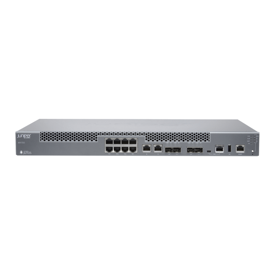
- Page 1 MX150 Universal Routing Platform Hardware Guide Modified: 2019-03-19 Copyright © 2019, Juniper Networks, Inc.
- Page 2 END USER LICENSE AGREEMENT The Juniper Networks product that is the subject of this technical documentation consists of (or is intended for use with) Juniper Networks software. Use of such software is subject to the terms and conditions of the End User License Agreement (“EULA”) posted at https://support.juniper.net/support/eula/.
-
Page 3: Table Of Contents
Management Port LEDs on MX150 ........23... - Page 4 Connecting AC Power to an MX150 ....... . . 55...
- Page 5 Packing a MX150 Router or Component for Shipping ....77 Packing an MX150 for Shipping ....... . . 78 Packing MX150 Components for Shipping .
- Page 6 Agency Approvals for MX150 ........
- Page 7 Figure 1: MX150 Port Panel ..........18 Figure 2: MX150 Front Panel Components ....... . 19 Figure 3: MX150 Rear Panel .
- Page 8 MX150 Universal Routing Platform Hardware Guide viii Copyright © 2019, Juniper Networks, Inc.
- Page 9 Table 4: Chassis Status LEDs in an MX150 ....... .
- Page 10 MX150 Universal Routing Platform Hardware Guide Copyright © 2019, Juniper Networks, Inc.
-
Page 11: About The Documentation
® To obtain the most current version of all Juniper Networks technical documentation, see the product documentation page on the Juniper Networks website at https://www.juniper.net/documentation/ If the information in the latest release notes differs from the information in the documentation, follow the product Release Notes. -
Page 12: Table 1: Notice Icons
MX150 Universal Routing Platform Hardware Guide Table 1: Notice Icons Icon Meaning Description Informational note Indicates important features or instructions. Caution Indicates a situation that might result in loss of data or hardware damage. Warning Alerts you to the risk of personal injury or death. -
Page 13: Documentation Feedback
We encourage you to provide feedback so that we can improve our documentation. You can use either of the following methods: Online feedback system—Click TechLibrary Feedback, on the lower right of any page on the Juniper Networks TechLibrary site, and do one of the following: Copyright © 2019, Juniper Networks, Inc. xiii... -
Page 14: Requesting Technical Support
Requesting Technical Support Technical product support is available through the Juniper Networks Technical Assistance Center (JTAC). If you are a customer with an active Juniper Care or Partner Support Services support contract, or are covered under warranty, and need post-sales technical support, you can access our tools and resources online or open a case with JTAC. -
Page 15: Creating A Service Request With Jtac
About the Documentation Join and participate in the Juniper Networks Community Forum: https://www.juniper.net/company/communities/ Create a service request online: https://myjuniper.juniper.net To verify service entitlement by product serial number, use our Serial Number Entitlement (SNE) Tool: https://entitlementsearch.juniper.net/entitlementsearch/ Creating a Service Request with JTAC You can create a service request with JTAC on the Web or by telephone. - Page 16 MX150 Universal Routing Platform Hardware Guide Copyright © 2019, Juniper Networks, Inc.
-
Page 17: Overview
The MX150 is 1 rack unit (U) tall. The MX150 can be mounted on a desk or any other level surface, on two posts in a Rack, and on four pots in a rack or Cabinet. The MX150 conserves space and contains costs associated with power and cooling. -
Page 18: System Software
An integrated branch router. A secure router for distributed enterprises. System Software The MX150 use the Junos OS CLI. You can manage the device by using the Junos CLI, accessible through the console and the out-of-band management ports on the device. MX150 Chassis... -
Page 19: Rear Panel Of An Mx150
Juniper Networks Technical Assistance Center (JTAC). See Also Prevention of Electrostatic Discharge Damage on page 104 Connecting an MX150 to a Network for Out-of-Band Management on page 56 Rear Panel of an MX150 The rear panel of the MX150 consists of the following components (see... -
Page 20: Chassis Status Leds On Mx150
2— Electrostatic discharge (ESD) point 5— AC power cord inlet 3—Exhaust vents Chassis Status LEDs on MX150 The front panel of an MX150 has chassis status LEDs (labeled next to the MGMT port (see Figure 4 on page 20). Figure 4: Chassis Status LEDs in an MX150 1—... -
Page 21: Network Port And Uplink Port Leds On Mx150
All three LEDs can be lit simultaneously. Network Port and Uplink Port LEDs on MX150 Each network port and uplink port on the front panel of an MX150 has two LEDs that indicate link activity and port status (see Figure 5 on page 21). -
Page 22: Figure 6: Port Parameter Leds Of An Mx150
2— Port parameter LEDs ( , and Table 6 on page 22 describes the port parameters LED. Table 6: Port Parameter LED on the Network Ports and Uplink Ports in MX150 Port Parameter LED State and Description SPD (speed) Indicates the speed. The speed indicators for network ports and uplink ports are: One blink per second—10 Mbps... -
Page 23: Management Port Leds On Mx150
Chapter 1: Overview Management Port LEDs on MX150 The management port on the front panel of an MX150 has two LEDs that indicate link activity and port status (see Figure 7 on page 23). Figure 7: LEDs on the Management Port of an MX150 1—... -
Page 24: Mx150 Cooling System
MX150 Universal Routing Platform Hardware Guide MX150 Cooling System The MX150 has front-to-back airflow. The air intake to cool the chassis is located at the front of the chassis. Air is pulled into the chassis and pushed toward the fans, which are built-in. -
Page 25: Ac Power Cord Specifications For An Mx150
Chapter 1: Overview Table 9: AC Power Specifications for an MX150 Item Specification AC input voltage Operating range: 100 through 240 VAC AC input line frequency 50–60 Hz nominal AC input current rating 3 A at 240 VAC Maximum power consumption... -
Page 26: Figure 9: Ac Plug Types
MX150 Universal Routing Platform Hardware Guide Table 10: AC Power Cord Specifications (continued) Country/Region Electrical Specifications Plug Standards Juniper Model Number Europe (except Italy, 250 VAC, 10 A, 50 Hz CEE (7) VII Type VIIG CBL-EX-PWR-C13-EU Switzerland, and United Kingdom) -
Page 27: Site Planning, Preparation, And Specifications
Site Preparation Checklist for MX150 on page 27 MX150 Site Guidelines and Requirements on page 29 MX150 Management and Console Port Specifications and Pinouts on page 34 MX150 Network Cable and Transceiver Planning on page 38 Site Preparation Checklist for MX150... - Page 28 Plan the cable routing and management. Related General Safety Guidelines and Warnings on page 82 Documentation Installing and Connecting an MX150 on page 45 Mounting an MX150 on page 48 Copyright © 2019, Juniper Networks, Inc.
-
Page 29: Mx150 Site Guidelines And Requirements
Clearance Requirements for Airflow and Hardware Maintenance for an MX150 on page 31 Requirements for Mounting an MX150 on a Desktop or Other Level Surface on page 32 Cabinet Requirements for an MX150 on page 32 Rack Requirements for an MX150 on page 33... -
Page 30: Environmental Requirements And Specifications For An Mx150
Electrical hazards as a result of power surges conducted over the lines into the equipment Environmental Requirements and Specifications for an MX150 The MX150 must be installed in a rack or cabinet. It must be housed in a dry, clean, well-ventilated, and temperature-controlled environment. -
Page 31: Figure 10: Clearance Requirements For Airflow And Hardware Maintenance For An Mx150
Leave at least 24 in. (61 cm) both in front of and behind the MX150. For service personnel to remove and install hardware components, you must leave adequate space at the front and back of the MX150. -
Page 32: Surface
Rack-Mounting and Cabinet-Mounting Warnings on page 89 Requirements for Mounting an MX150 on a Desktop or Other Level Surface You can install the MX150 on a desktop or other such level surface, by attaching the four rubber feet (provided) to the bottom of the chassis. -
Page 33: Rack Requirements For An Mx150
Chapter 2: Site Planning, Preparation, and Specifications Rack Requirements for an MX150 You can mount the MX150 on two-post racks or four-post racks. Rack requirements consist of: Rack type Mounting bracket hole spacing Rack size and strength Rack connection to the building structure Table 15 on page 33 provides the rack requirements and specifications for the MX150. -
Page 34: Mx150 Management And Console Port Specifications And Pinouts
MX150 Universal Routing Platform Hardware Guide Mounting an MX150 on Two Posts in a Rack on page 49 Mounting an MX150 on Four Posts in a Rack or Cabinet on page 51 MX150 Management and Console Port Specifications and Pinouts... -
Page 35: Console Port Connector Pinouts For Mx150
If your laptop or PC does not have a DB-9 male connector pin and you want to connect your laptop or PC directly to an MX150 device, use a combination of the RJ-45 cable and RJ-45 to DB-9 adapter supplied with the device and a USB to DB-9 male adapter. -
Page 36: Management Port Connector Pinout Information For An Mx150
USB flash drive with at least 4 GB of free space. We recommend using the RE-USB-4G-S flash drive. NOTE: USB flash drives used with the MX150 must support USB 2.0 or later. See Also Front Panel of an MX150 on page 18... -
Page 37: Network Port Connector Pinout Information For An Mx150
Management Port LEDs on MX150 on page 23 Network Port Connector Pinout Information for an MX150 A network port on an MX150 uses an RJ-45 connector to connect to a device. The port uses an autosensing RJ-45 connector to support a 10/100/1000Base-T connection. -
Page 38: Rj-45 To Db-9 Serial Port Adapter Pinout Information For An Mx150
PC or a laptop. If your laptop or PC does not have a DB-9 male connector pin and you want to connect your laptop or PC to an MX150, use a combination of the RJ-45 to DB-9 female adapter supplied with the switch along with a USB to DB-9 male adapter. -
Page 39: Sfp+ Direct Attach Copper Cables For Mx150
Standards Supported by These Cables on page 40 Cable Specifications MX150 routers support SFP+ passive DAC cables. The passive Twinax cable is a straight cable with no active electronic components. MX150 routers support 1 m, 3 m, and 5 m long SFP+ passive DAC cables. NOTE: We recommend that you use only SFP+ DAC cables purchased from Juniper Networks with your Juniper Networks device. -
Page 40: Standards Supported By These Cables
(JTAC) can help you diagnose the source of the problem. Your JTAC engineer might recommend that you check the third-party optic or cable and potentially replace it with an equivalent Juniper Networks optic or cable that is qualified for the device. -
Page 41: Dispersion
Chapter 2: Site Planning, Preparation, and Specifications Table 21: Cable Specifications for Console and Management Connections for the MX150 (continued) Port on MX150 Maximum Device Device Cable Specification Cable Supplied Length Receptacle Management port Category 5 cable or equivalent One 2.13-meter-long RJ-45 2.13 meters... -
Page 42: Calculating The Fiber-Optic Cable Power Budget For An Mx150
(including those from dispersion), and a safety margin for unexpected losses. Calculating the Fiber-Optic Cable Power Budget for an MX150 Calculate the link's power budget when planning fiber-optic cable layout and distances to ensure that fiber-optic connections have sufficient power for correct operation. The power budget is the maximum amount of power the link can transmit. -
Page 43: Calculating The Fiber-Optic Cable Power Margin For An Mx150
) from (PT): –15 dBm – (–28 dBm) = 13 dBm Calculating the Fiber-Optic Cable Power Margin for an MX150 Calculate the link's power margin when planning fiber-optic cable layout and distances to ensure that fiber-optic connections have sufficient signal power to overcome system losses and still satisfy the minimum input requirements of the receiver for the required performance level. - Page 44 MX150 Universal Routing Platform Hardware Guide Table 22: Estimated Values for Factors Causing Link Loss (continued) Link-Loss Factor Estimated Link-Loss Value Sample Link Loss (LL) Calculation Values Fiber attenuation Multimode—1 dBm/km This example assumes the link is 2 km long. Fiber attenuation for 2 km: 2 km (1 dBm/km) = 2 dBm.
-
Page 45: Chapter 3 Initial Installation And Configuration
“Mounting an MX150 on Two Posts in a Rack” on page 49 (using the mounting brackets provided) “Mounting an MX150 on Four Posts in a Rack or Cabinet” on page 51 (using the separately orderable four-post rack-mount kit) Follow instructions in “Connecting Earth Ground to an MX150”... -
Page 46: Unpacking And Mounting The Mx150
Mounting an MX150 on a Desk or Other Level Surface on page 48 Mounting an MX150 on Two Posts in a Rack on page 49 Mounting an MX150 on Four Posts in a Rack or Cabinet on page 51 Unpacking an MX150 The MX150 is shipped in a cardboard carton, secured with foam packing material. -
Page 47: Registering Products-Mandatory For Validating Slas
See Also MX150 Router Overview on page 17 Registering Products—Mandatory for Validating SLAs Register all new Juniper Networks hardware products and changes to an existing installed product using the Juniper Networks website to activate your hardware replacement service-level agreements (SLAs). -
Page 48: Mounting An Mx150
Mounting an MX150 on a Desk or Other Level Surface You can mount an MX150 on a desk or other level surface by using the four rubber feet that are shipped with the router. The rubber feet stabilize the chassis. -
Page 49: Mounting An Mx150 On Two Posts In A Rack
Clearance Requirements for Airflow and Hardware Maintenance for an MX150 on page 31 Mounting an MX150 on Two Posts in a Rack You can mount an MX150 on two posts of a 19-in. rack (either a two-post or a four-post rack). NOTE: If you need to mount the MX150 in a recessed position on either a two-post rack or a four-post rack, you can use the 2-in.-recess front brackets... -
Page 50: Figure 12: Attaching The Mounting Bracket To The Side Panel Of The Mx150
Figure 12 on page Figure 12: Attaching the Mounting Bracket to the Side Panel of the MX150 NOTE: If you need to mount the MX150 in a recessed position, use the 2-in.-recess front-mount brackets from the separately orderable four-post... -
Page 51: Mounting An Mx150 On Four Posts In A Rack Or Cabinet
Mounting an MX150 on Four Posts in a Rack or Cabinet You can mount an MX150 on four posts of a 19-in. rack or cabinet by using the separately orderable four-post rack-mount kit. (The remainder of this topic uses rack to mean rack or cabinet.). - Page 52 To mount the MX150 on four posts in a rack: Place the router on a flat, stable surface.
-
Page 53: Figure 14: Attaching The Front-Mounting Bracket To The Chassis
See Figure 15 on page Figure 15: Mounting the MX150 on the Front Posts in a Rack Have a second person secure the front of the device to the rack by using the appropriate screws for your rack. -
Page 54: Connecting The Mx150 To Power
Electromagnetic compatibility (EMC) and electrostatic discharge (ESD) requirements are met by the chassis. The AC power cord provides surge protection. To connect MX150 to earth ground, you must use the protective earthing terminal on the device chassis. See Figure 16 on page... -
Page 55: Connecting Ac Power To An Mx150
Ensure that the cable does not drape where people could trip over it. Connecting AC Power to an MX150 The power supply in an MX150 is located on the rear panel. Ensure that you have the following parts and tools available: A power cord appropriate for your geographical location... -
Page 56: Connecting The Mx150 To The Network
The retainer brackets on your switch might be above and below the power inlet rather than on either side. Figure 17: Connecting an AC Power Cord to the AC Power Cord Inlet on MX150 See Also AC Power Supply Specifications for an MX150 on page 24... -
Page 57: Connecting An Mx150 To A Management Console
Front Panel of an MX150 on page 18 Connecting an MX150 to a Management Console MX150 has a console port with an RJ-45 connector. Use the console port to connect the device to a management console or to a console server. -
Page 58: Connecting An Mx150 To A Management Console Using Mini-Usb Type-B
If your laptop or PC does not have a DB-9 male connector pin or RJ-45 connector pin, you can connect your laptop or PC directly to an MX150 device by using a mini-USB cable that has a Standard-A USB connector on one end and a Mini-USB Type-B (5 pin) connector on the other end. - Page 59 Chapter 3: Initial Installation and Configuration For information about configuring and managing an MX150 by using the RJ-45 console port, see “Connecting an MX150 to a Management Console” on page Before you begin connecting an MX150 by using the Mini-USB Type-B console port: Ensure that the USB to Serial driver is installed on the host machine.
-
Page 60: Performing The Initial Software Configuration For The Mx150
MX150 Universal Routing Platform Hardware Guide Performing the Initial Software Configuration for the MX150 You must perform the initial configuration of the MX150 through the console port using the command-line interface (CLI). Before you begin connecting and configuring an MX150, set the following parameter values on the console server or PC: Baud Rate—9600... - Page 61 To configure an IPV6 address, run the root@host# set interface fxp0 family inet6 address address v6_address NOTE: is found on the front panel of the MX150 device. fxp0 Configure the default gateway. [edit] root@host# set routing-options static route default next-hop address Enable the SSH service.
- Page 62 MX150 Universal Routing Platform Hardware Guide Copyright © 2019, Juniper Networks, Inc.
-
Page 63: Maintaining Components
(FRUs). You can remove and replace them without powering off the device or disrupting device functions. Before you begin removing a transceiver from the MX150, ensure that you have taken the necessary precautions for safe handling of lasers (see “Laser and LED Safety Guidelines... - Page 64 MX150 Universal Routing Platform Hardware Guide WARNING: Do not look directly into a fiber-optic transceiver or into the ends of fiber-optic cables. Fiber-optic transceivers and fiber-optic cables connected to transceivers emit laser light that can damage your eyes. WARNING: Do not leave a fiber-optic transceiver uncovered except when inserting or removing a cable.
-
Page 65: Installing A Transceiver In An Mx150
(FRUs). You can remove and replace them without powering off the device or disrupting device functions. Before you begin installing a transceiver in an MX150, ensure that you have taken the necessary precautions for safe handling of lasers (see “Laser and LED Safety Guidelines... -
Page 66: Maintaining Fiber-Optic Cables In An Mx150
Fiber-optic transceivers and fiber-optic cables connected to transceivers emit laser light that can damage your eyes. Figure 22: Installing a Transceiver in an MX150 Maintaining Fiber-Optic Cables in an MX150 To maintain fiber-optic cables in MX150: When you unplug a fiber-optic cable from a transceiver, place rubber safety caps over the transceiver and on the end of the cable. -
Page 67: Connecting A Fiber-Optic Cable To An Mx150
You can connect fiber-optic cables to the field-replaceable unit (FRU) optical transceivers installed in MX150 routers. Before you connect a fiber-optic cable to an optical transceiver installed in an MX150, ensure that you have taken the necessary precautions for safe handling of lasers (see “Laser and LED Safety Guidelines and Warnings for the MX150”... -
Page 68: Disconnecting A Fiber-Optic Cable From An Mx150
Disconnecting a Fiber-Optic Cable from an MX150 Before you disconnect a fiber-optic cable from an optical transceiver installed in an MX150, ensure that you have taken the necessary precautions for safe handling of lasers (see “Laser and LED Safety Guidelines and Warnings for the MX150” on page 92). -
Page 69: Removing The Mx150
Removing an MX150 from a Rack or Cabinet on page 71 Powering Off an MX150 If you need to power off the MX150, follow the procedure in this topic. Before you power off the device: Ensure that you understand how to prevent electrostatic discharge damage. See “Prevention of Electrostatic Discharge Damage”... - Page 70 Management Console” on page For connecting a management device to the management port, see “Connecting an MX150 to a Network for Out-of-Band Management” on page 56 From the PC connected to the device, issue the following operational mode CLI command: user@host>...
-
Page 71: Removing An Mx150 From A Rack Or Cabinet
Connecting AC Power to an MX150 on page 55 Removing an MX150 from a Rack or Cabinet If you need to relocate an installed MX150, use the procedure described in this topic. (The remainder of this topic uses rack to mean rack or cabinet.) - Page 72 Lift the chassis from the rack and carefully move the chassis to its new location. See Also General Safety Guidelines and Warnings on page 82 Chassis Lifting Guidelines for MX150 on page 87 Copyright © 2019, Juniper Networks, Inc.
-
Page 73: Troubleshooting Hardware
Understanding Alarm Types and Severity Levels on MX150 on page 73 Understanding Alarm Types and Severity Levels on MX150 Alarms alert you to conditions that might prevent normal operation of the MX150. Table 26 on page 73 provides a list of alarm terms and definitions that might help you in monitoring the device. - Page 74 MX150 Universal Routing Platform Hardware Guide Related MX150 Router Overview on page 17 Documentation Copyright © 2019, Juniper Networks, Inc.
-
Page 75: Components
Returning a MX150 Router or Component for Repair or Replacement on page 79 Contacting Customer Support to Obtain a Return Materials Authorization for an MX150 If you are returning an MX150 router or component to Juniper Networks for repair or replacement, obtain a Return Materials Authorization (RMA) from the Juniper Networks Technical Assistance Center (JTAC). -
Page 76: Locating The Serial Number On An Mx150
If you are returning a device to Juniper Networks for repair or replacement, you must locate the serial number of the device. You must provide the serial number to the Juniper Networks Technical Assistance Center (JTAC) when you contact them to obtain Return Materials Authorization (RMA). -
Page 77: Locating The Chassis Serial Number Id Label On An Mx150
Locating the Chassis Serial Number ID Label on an MX150 The serial number ID label is located on the back of the chassis on an MX150. See Figure 24 on page Figure 24: Location of the Serial Number ID Label on an MX150... -
Page 78: Packing An Mx150 For Shipping
Packing MX150 Components for Shipping on page 78 Packing an MX150 for Shipping To pack an MX150 for shipping: Power off the MX150 and remove the power cables. See “Powering Off an MX150” on page Remove the cables that connect the device to all external devices. -
Page 79: Returning A Mx150 Router Or Component For Repair Or Replacement
Write the RMA number on the exterior of the box to ensure proper tracking. Returning a MX150 Router or Component for Repair or Replacement If you need to return a MX150 router or component to Juniper Networks for repair or replacement, follow this procedure: Determine the serial number of the device or component. - Page 80 MX150 Universal Routing Platform Hardware Guide Copyright © 2019, Juniper Networks, Inc.
-
Page 81: Safety And Compliance Information
Ramp Warning on page 88 Rack-Mounting and Cabinet-Mounting Warnings on page 89 Laser and LED Safety Guidelines and Warnings for the MX150 on page 92 Radiation from Open Port Apertures Warning on page 96 Maintenance and Operational Safety Guidelines and Warnings on page 97... -
Page 82: General Safety Guidelines And Warnings
MX150 Universal Routing Platform Hardware Guide General Safety Guidelines and Warnings The following guidelines help ensure your safety and protect the device from damage. The list of guidelines might not address all potentially hazardous situations in your working environment, so be alert and exercise good judgment at all times. -
Page 83: Definitions Of Safety Warning Levels
Avant de travailler sur un équipement, soyez conscient des dangers posés par les circuits électriques et familiarisez-vous avec les procédures couramment utilisées pour éviter les accidents. Copyright © 2019, Juniper Networks, Inc. -
Page 84: Qualified Personnel Warning
MX150 Universal Routing Platform Hardware Guide Warnung Dieses Warnsymbol bedeutet Gefahr. Sie befinden sich in einer Situation, die zu einer Körperverletzung führen könnte. Bevor Sie mit der Arbeit an irgendeinem Gerät beginnen, seien Sie sich der mit elektrischen Stromkreisen verbundenen Gefahren und der Standardpraktiken zur Vermeidung von Unfällen bewußt. -
Page 85: Warning Statement For Norway And Sweden
In addition, you should establish procedures to protect your equipment in the event of a fire emergency. Juniper Networks products should be installed in an environment suitable for electronic equipment. We recommend that fire suppression equipment be available in the event of a fire in the vicinity of the equipment and that all local fire, safety, and electrical codes and ordinances be observed when you install and operate your equipment. -
Page 86: Installation Instructions Warning
To keep warranties effective, do not use a dry chemical fire extinguisher to control a fire at or near a Juniper Networks device. If a dry chemical fire extinguisher is used, the unit is no longer eligible for coverage under a service agreement. -
Page 87: Chassis Lifting Guidelines For Mx150
Chassis Lifting Guidelines for MX150 The weight of an MX150 is approximately 9.4 lb (4.3 kg). Observe the following guidelines for lifting and moving an MX150: Before installing the MX150, verify that the intended site meets the specified power, environmental, and clearance requirements. -
Page 88: Ramp Warning
MX150 Universal Routing Platform Hardware Guide Schlüssel oder anderer Sicherheitsvorkehrungen Zugang hat, und der von dem für die Anlage zuständigen Gremium kontrolliert wird. Avvertenza Questa unità deve essere installata in un'area ad accesso limitato. Un'area ad accesso limitato è un'area accessibile solo a personale di assistenza tramite un'attrezzo speciale, lucchetto, o altri dispositivi di sicurezza, ed è... -
Page 89: Rack-Mounting And Cabinet-Mounting Warnings
De onderstaande richtlijnen worden verstrekt om uw veiligheid te verzekeren: De Juniper Networks switch moet in een stellage worden geïnstalleerd die aan een bouwsel is verankerd. Dit toestel dient onderaan in het rek gemonteerd te worden als het toestel het enige in het rek is. - Page 90 Les directives ci-dessous sont destinées à assurer la protection du personnel: Le rack sur lequel est monté le Juniper Networks switch doit être fixé à la structure du bâtiment. Si cette unité constitue la seule unité montée en casier, elle doit être placée dans le bas.
- Page 91 Le seguenti direttive vengono fornite per garantire la sicurezza personale: Il Juniper Networks switch deve essere installato in un telaio, il quale deve essere fissato alla struttura dell'edificio. Questa unità deve venire montata sul fondo del supporto, se si tratta dell'unica unità...
-
Page 92: Laser And Led Safety Guidelines And Warnings For The Mx150
Para garantizar su seguridad, proceda según las siguientes instrucciones: El Juniper Networks switch debe instalarse en un bastidor fijado a la estructura del edificio. Colocar el equipo en la parte inferior del bastidor, cuando sea la única unidad en el mismo. -
Page 93: General Laser Safety Guidelines
Varning! Laserprodukter av Klass 1M (IEC). Class 1M Laser Radiation Warning WARNING: Class 1M laser radiation when open. Do not view directly with optical instruments. Class 1 Laser Product Warning WARNING: Class 1 laser product. Copyright © 2019, Juniper Networks, Inc. -
Page 94: Class 1 Led Product Warning
MX150 Universal Routing Platform Hardware Guide Waarschuwing Klasse-1 laser produkt. Varoitus Luokan 1 lasertuote. Attention Produit laser de classe I. Warnung Laserprodukt der Klasse 1. Avvertenza Prodotto laser di Classe 1. Advarsel Laserprodukt av klasse 1. Aviso Produto laser de classe 1. -
Page 95: Unterminated Fiber-Optic Cable Warning
à une distance inférieure à 100 mm peut poser des risques pour les yeux. Warnung Eine unsichtbare Laserstrahlung kann vom Ende des nicht angeschlossenen Glasfaserkabels oder Steckers ausgestrahlt werden. Nicht in den Laserstrahl schauen oder diesen mit einem optischen Instrument direkt Copyright © 2019, Juniper Networks, Inc. -
Page 96: Radiation From Open Port Apertures Warning
MX150 Universal Routing Platform Hardware Guide ansehen. Ein Betrachten des Laserstrahls mit bestimmten optischen Instrumenten, wie z.B. Augenlupen, Vergrößerungsgläsern und Mikroskopen innerhalb eines Abstands von 100 mm kann für das Auge gefährlich sein. Avvertenza L'estremità del connettore o del cavo ottico senza terminazione può... -
Page 97: Maintenance And Operational Safety Guidelines And Warnings
While performing the maintenance activities for devices, observe the following guidelines and warnings: Battery Handling Warning on page 98 Jewelry Removal Warning on page 99 Lightning Activity Warning on page 100 Operating Temperature Warning on page 100 Product Disposal Warning on page 102 Copyright © 2019, Juniper Networks, Inc. -
Page 98: Battery Handling Warning
MX150 Universal Routing Platform Hardware Guide Battery Handling Warning WARNING: Replacing a battery incorrectly might result in an explosion. Replace a battery only with the same or equivalent type recommended by the manufacturer. Dispose of used batteries according to the manufacturer's instructions. -
Page 99: Jewelry Removal Warning
à terra, podendo causar queimaduras graves ou ficarem soldados aos terminais. ¡Atención! Antes de operar sobre equipos conectados a líneas de alimentación, quitarse las joyas (incluidos anillos, collares y relojes). Los Copyright © 2019, Juniper Networks, Inc. -
Page 100: Lightning Activity Warning
MX150 Universal Routing Platform Hardware Guide objetos de metal se calientan cuando se conectan a la alimentación y a tierra, lo que puede ocasionar quemaduras graves o que los objetos metálicos queden soldados a los bornes. Varning! Tag av alla smycken (inklusive ringar, halsband och armbandsur) innan du arbetar på... - Page 101 6 in. (15.2 cm) of clearance around the ventilation openings. Waarschuwing Om te voorkomen dat welke switch van de Juniper Networks router dan ook oververhit raakt, dient u deze niet te bedienen op een plaats waar de maximale aanbevolen omgevingstemperatuur van 40°...
-
Page 102: Product Disposal Warning
MX150 Universal Routing Platform Hardware Guide inskränks genom att se till att det finns fritt utrymme på minst 15,2 cm omkring ventilationsöppningarna. Product Disposal Warning WARNING: Disposal of this device must be handled according to all national laws and regulations. -
Page 103: Action To Take After An Electrical Accident
Use caution. Be aware of potentially hazardous conditions that could cause further injury. Disconnect power from the device. If possible, send another person to get medical aid. Otherwise, assess the condition of the victim, then call for help. Copyright © 2019, Juniper Networks, Inc. -
Page 104: Prevention Of Electrostatic Discharge Damage
MX150 Universal Routing Platform Hardware Guide Prevention of Electrostatic Discharge Damage Device components that are shipped in antistatic bags are sensitive to damage from static electricity. Some components can be impaired by voltages as low as 30 V. You can easily generate potentially damaging static voltages whenever you handle plastic or foam packing material or if you move components across plastic or carpets. -
Page 105: Ac Power Electrical Safety Guidelines
To disconnect power, unplug all power cords (one for each power supply). Power Cable Warning (Japanese) WARNING: The attached power cable is only for this product. Do not use the cable for another product. Copyright © 2019, Juniper Networks, Inc. -
Page 106: Ac Power Disconnection Warning
MX150 Universal Routing Platform Hardware Guide AC Power Disconnection Warning WARNING: Before working on the device or near power supplies, unplug all the power cords from an AC-powered device. Waarschuwing Voordat u aan een frame of in de nabijheid van voedingen werkt, dient u bij wisselstroom toestellen de stekker van het netsnoer uit het stopcontact te halen. -
Page 107: Agency Approvals For Mx150
TN. Varning! Enheten är konstruerad för användning tillsammans med elkraftssystem av TN-typ. Agency Approvals for MX150 The MX150 complies with the following standards: Safety CAN/CSA-C22.2 No. 60950-1 Information Technology Equipment UL 60950-1 Information Technology Equipment EN 60950-1 Information Technology Equipment... -
Page 108: Compliance Statements For Emc Requirements For Mx150
EN 61000-4-6 Low Frequency Common Immunity EN 61000-4-11 Voltage Dips and Sags Related Compliance Statements for EMC Requirements for MX150 on page 108 Documentation Compliance Statements for EMC Requirements for MX150 This topic describes the EMC requirements for the MX150 :... -
Page 109: European Community
Japan The preceding translates as follows: This is a Class A device. In a domestic environment this device might cause radio interference, in which case the user needs to take adequate measures. VCCI-A Copyright © 2019, Juniper Networks, Inc. -
Page 110: Korea
MX150 Universal Routing Platform Hardware Guide Korea Korean Class A Warning The preceding translates as follows: This equipment is Industrial (Class A) electromagnetic wave suitability equipment and seller or user should take notice of it, and this equipment is to be used in the places except... -
Page 111: Nonregulatory Environmental Standards
Chapter 7: Safety and Compliance Information Nonregulatory Environmental Standards NEBS compliance—These MX150 devices are Network Equipment Building System (NEBS) compliant. Those devices are designed to meet the following NEBS compliance standards: SR-3580 NEBS Criteria Levels (Level 4 Compliance) GR-1089-CORE: EMC and Electrical Safety for Network Telecommunications Equipment... - Page 112 MX150 Universal Routing Platform Hardware Guide Copyright © 2019, Juniper Networks, Inc.
Need help?
Do you have a question about the MX150 and is the answer not in the manual?
Questions and answers