Juniper SRX340 Hardware Manual
Firewall
Hide thumbs
Also See for SRX340:
- Hardware manual (150 pages) ,
- Quick start manual (12 pages) ,
- How to set up (8 pages)
Table of Contents
Advertisement
Quick Links
Advertisement
Table of Contents
Troubleshooting

Subscribe to Our Youtube Channel
Related Manuals for Juniper SRX340


Summary of Contents for Juniper SRX340
- Page 1 SRX340 Firewall Hardware Guide Published 2023-08-15...
- Page 2 The Juniper Networks product that is the subject of this technical documentation consists of (or is intended for use with) Juniper Networks software. Use of such software is subject to the terms and conditions of the End User License Agreement ("EULA") posted at https:/ /support.juniper.net/support/eula/.
-
Page 3: Table Of Contents
General Site Installation Guidelines for the SRX340 Firewall | 18 SRX340 Firewall Environmental Specifications | 19 SRX340 Firewall Electrical Wiring Guidelines | 19 SRX340 Firewall Physical Specifications | 21 SRX340 Firewall Clearance Requirements for Airflow and Hardware Maintenance | 22... - Page 4 Powering Off the SRX340 Services Gateway | 39 Connecting the SRX340 to External Devices | 40 Connecting the Dial-Up Modem to the Console Port on the SRX340 Services Gateway | 40 Connecting to the SRX340 Firewall CLI Using a Dial-Up Modem | 41...
- Page 5 Maintaining Components Maintaining the SRX340 Components | 59 Required Tools and Parts for Maintaining the SRX340 Firewall Hardware Components | 59 Routine Maintenance Procedures for the SRX340 Services Gateway | 59 Maintaining the SRX340 Firewall Cooling System Components | 60...
- Page 6 Returning a SRX340 Firewall Component to Juniper Networks | 70 Locating the SRX340 Firewall Chassis Serial Number and Agency Labels | 70 Locating the SRX340 Firewall Mini-Physical Interface Module Serial Number Label | 71 Listing the SRX340 Firewall Component Details with the CLI | 71...
-
Page 7: About This Guide
Use this guide to install hardware and perform initial software configuration, routine maintenance, and troubleshooting for the SRX340 Firewall. After completing the installation and basic configuration procedures covered in this guide, refer to the Junos OS documentation for information about further software configuration. -
Page 8: Overview
C HAPTER Overview SRX340 Firewall Overview | 2 SRX340 Chassis | 3 SRX340 Cooling System | 11 SRX340 Power System | 12... -
Page 9: Srx340 Firewall Overview
The SRX340 Firewall has a capacity of 3 gigabits per second (Gbps) and is 1 rack unit (U) tall. The services gateway has eight 1 G Ethernet ports, eight 1 G SFP ports, one management port, 4 GB of DRAM memory, 8 GB of flash memory, and four Mini-Physical Interface Module (Mini-PIM) slots. -
Page 10: Benefits Of The Srx340 Firewall
Replacing Mini-Physical Interface Modules in the SRX340 Firewall | 60 Benefits of the SRX340 Firewall • High performance—The SRX340 supports up to 3-Gbps firewall and 600-Mbps IPsec VPN, and is suited for midsize distributed enterprise branch office deployments. • Simplified deployment with minimal manual intervention—The Zero Touch Provisioning (ZTP) feature enables you to provision and configure the SRX300 line automatically, thereby reducing operational complexity and simplifying the provisioning of new sites. -
Page 11: Srx340 Firewall Chassis Overview
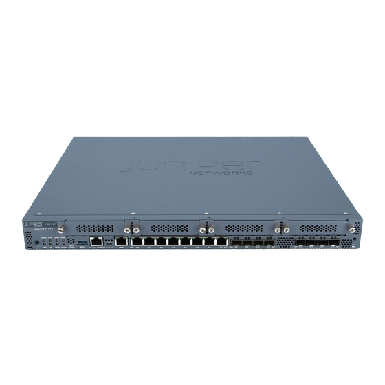
SRX340 Firewall Interface Modules Overview | 10 SRX340 Firewall Chassis Overview The SRX340 Firewall chassis is a rigid sheet metal structure that houses all of the other services gateway components. The chassis measures 1.72 in. (4.36 cm) high, 17.36 in. (44.09 cm) wide, and 14.57 in. - Page 12 Figure 1: SRX340 Firewall Front Panel Table 1 on page 5 provides details about the front panel components. Table 1: SRX340 Firewall Front Panel Components Callout Component Description Reset Config button Returns the services gateway to the rescue configuration or the factory-default configuration.
- Page 13 (Continued) Table 1: SRX340 Firewall Front Panel Components Callout Component Description Mini-PIM slots Four slots for Mini-PIMs. Mini-PIMs can be used to provide LAN and WAN functionality along with connectivity to various media types. ESD point For personal safety, while working on the services gateway,...
- Page 14 (Continued) Table 1: SRX340 Firewall Front Panel Components Callout Component Description Power button Use the Power button to power on or power off the services gateway. Figure 2 on page 7 shows the LEDs on the front panel. Figure 2: SRX340 Firewall Front Panel LEDs Table 2 on page 7 lists the front panel LEDs.
- Page 15 (Continued) Table 2: SRX340 Firewall Front Panel LEDs Component Description • Solid green (all HA links are available) • Solid amber (some HA links are unavailable) • Solid red (HA links are not functional) • Off (HA is disabled) mPIM0 , mPIM1, mPIM2, and mPIM3 •...
-
Page 16: Srx340 Firewall Back Panel
• Off—There is no link activity. SRX340 Firewall Back Panel Figure 3 on page 9 shows the back panel of the SRX340 Firewall and Table 5 on page 9 lists the components on the back panel. Figure 3: SRX340 Firewall Back Panel... -
Page 17: Srx340 Firewall Interface Modules Overview
• 1-Port VDSL2 (Annex A) Mini-Physical Interface Module (SRX-MP-1VDSL2-R) • LTE Mini-Physical Interface Module (SRX-MP-LTE-AE and SRX-MP-LTE-AA) • Wi-Fi Mini-Physical Interface Module (SRX-MP-WLAN-US, SRX-MP-WLAN-IL, and SRX-MP-WLAN- NOTE: Gigabit-Backplane Physical Interface Modules (GPIMs) are not supported on the SRX340 Firewall. For more information on the Mini-PIMs, see the... -
Page 18: Srx340 Cooling System
SRX340 Cooling System The cooling system for the SRX340 Firewall includes four fixed fans. The fans draw air through vents on the front of the chassis and exhaust the air through the back of the chassis. The airflow produced by the fans keeps device components within the acceptable temperature range. -
Page 19: Srx340 Power System
SRX340 Firewall Supported AC Power Cords | 13 Understanding the SRX340 Firewall Power Supply The SRX340 Firewall uses a fixed, internal AC power supply. The power supply distributes the different output voltages to the device components according to their voltage requirements. The power supply is fixed in the chassis and is not field-replaceable. -
Page 20: Srx340 Firewall Supported Ac Power Cords
(Continued) Table 6: Power System Electrical Specifications for the SRX340 Firewall Power Requirement Specification AC system current rating 1 to 1.5 A Maximum AC inrush current 7.3 A at 220 V/50 Hz (with four Mini-PIMs installed) WARNING: The AC power cord for the services gateway is intended for use with the device only and not for any other use. - Page 21 250 VAC, 10 A, 50 Hz BS 1363A Figure 5: AC Plug Types NOTE: Power cords and cables must not block access to services gateway components or drape where people might trip on them. RELATED DOCUMENTATION SRX340 Firewall Electrical Wiring Guidelines | 19...
-
Page 22: Site Planning, Preparation, And Specifications
C HAPTER Site Planning, Preparation, and Specifications Site Preparation Checklist for the SRX340 Firewall | 16 SRX340 Site Guidelines and Requirements | 18 SRX340 Transceiver Specifications and Pinouts | 24... -
Page 23: Site Preparation Checklist For The Srx340 Firewall
Site Preparation Checklist for the SRX340 Firewall Table 8 on page 16 provides a checklist of tasks you need to perform when preparing a site for installing the SRX340 Firewall. Table 8: Site Preparation Checklist for SRX340 Firewall Installation Item or Task Additional Information Performed... - Page 24 (Continued) Table 8: Site Preparation Checklist for SRX340 Firewall Installation Item or Task Additional Information Performed Date Notes Rack Installation Plan the rack location, "Preparing the SRX340 Services including required space Gateway for Rack-Mount Installation" clearances. on page 33 Secure the rack to the floor Connecting the SRX340 Services and building structure.
-
Page 25: Srx340 Site Guidelines And Requirements
Cabinet Requirements for the SRX340 Firewall | 23 General Site Installation Guidelines for the SRX340 Firewall The following precautions help you plan an acceptable operating environment for your SRX340 Firewall and avoid environmentally caused equipment failures: • For the cooling system to function properly, the airflow around the chassis must be unrestricted. -
Page 26: Srx340 Firewall Environmental Specifications
SEE ALSO Site Preparation Checklist for the SRX340 Firewall | 16 SRX340 Firewall Environmental Specifications Table 9 on page 19 provides the required environmental conditions for normal SRX340 Firewall operations. Table 9: Environmental Specifications for the SRX340 Firewall Description Value... - Page 27 CAUTION: It is particularly important to provide a properly grounded and shielded environment and to use electrical surge-suppression devices. Table 10: Site Electrical Wiring Guidelines for the SRX340 Firewall Site Wiring Factor Guideline Signaling Limitations To ensure that signaling functions optimally: •...
-
Page 28: Srx340 Firewall Physical Specifications
(Continued) Table 10: Site Electrical Wiring Guidelines for the SRX340 Firewall Site Wiring Factor Guideline Electromagnetic Compatibility Provide a properly grounded and shielded environment and use electrical (EMC) surge-suppression devices. Strong sources of electromagnetic interference (EMI) can cause the following damage: •... -
Page 29: Srx340 Firewall Clearance Requirements For Airflow And Hardware Maintenance
SRX340 Firewall Clearance Requirements for Airflow and Hardware Maintenance When planning the installation site for the SRX340 Firewall, you need to allow sufficient clearance around the device. Consider the following: • For the operating temperature of the services gateway to be optimal, the airflow around the chassis must be unrestricted. -
Page 30: Rack Requirements For The Srx340 Services Gateway
(top and bottom mounting hole). Cabinet Requirements for the SRX340 Firewall You can install the SRX340 Firewall in a 19 in. (48.7 cm) cabinet as defined in Cabinets, Racks, Panels, and Associated Equipment (document number EIA-310-D) published by the Electronic Industries... -
Page 31: Srx340 Transceiver Specifications And Pinouts
NOTE: A cabinet larger than the minimum required provides better airflow and reduces the chance of overheating. When you mount the SRX340 Firewall in a cabinet, you must ensure that ventilation through the cabinet is sufficient to prevent overheating. Consider the following when planning for chassis cooling: •... -
Page 32: Rj-45 Connector Pinouts For The Srx340 Firewall Ethernet Port
The Hardware Compatibility Tool enables you to search by product, displaying all the transceivers supported on that device, or category, by interface speed or type. The list of supported transceivers for the SRX340 is located at https:/ /apps.juniper.net/hct/product/#prd=SRX340. -
Page 33: Mini-Usb Connector Pinouts For The Srx340 Firewall Console Port
Mini-USB Connector Pinouts for the SRX340 Firewall Console Port The SRX340 Firewall has two console ports: an RJ-45 Ethernet port and a mini-USB Type-B port. If your management device (laptop or PC) does not have a DB-9 plug connector pin or an RJ-45 connector pin,... - Page 34 Table 14: Mini-USB Type-B Connector Pinouts for the Services Gateway Console Port Signal Cable Color Description +5 VDC White Data - Green Data + Could be not connected (N/C), connected to ground (GND), or used as an attached device presence indicator Black Ground...
-
Page 35: Initial Installation And Configuration
Unpacking and Mounting the SRX340 | 30 Connecting the SRX340 to Power | 35 Connecting the SRX340 to External Devices | 40 Configuring Junos OS on the SRX340 | 42 Installing the Optional SATA Solid-State Drive in SRX340 and SRX345 Services Gateways | 54... -
Page 36: Srx340 Installation Overview
SRX340 Firewall Autoinstallation Overview | 29 SRX340 Firewall Installation Overview After you have prepared the site for installation and unpacked the SRX340 Firewall, you are ready to install the device. It is important to proceed through the installation process in the following order: 1. -
Page 37: Unpacking And Mounting The Srx340
For more information about configuring autoinstallation, see the following topics: • Installation and Upgrade Guide for Security Devices • Network Management and Monitoring Guide Unpacking and Mounting the SRX340 IN THIS SECTION Unpacking the SRX340 Firewall | 31 Verifying Parts Received with the SRX340 Firewall | 32... -
Page 38: Unpacking The Srx340 Firewall
• Phillips (+) screwdriver, number 2 • Blank panels to cover any slots not occupied by a component The SRX340 Firewall is shipped in a cardboard carton and secured with foam packing material. The carton also contains an accessory box and quick start instructions. -
Page 39: Verifying Parts Received With The Srx340 Firewall
Verifying Parts Received with the SRX340 Firewall The SRX340 Firewall shipment package contains a packing list. Check the parts in the shipment against the items on the packing list. The packing list specifies the part numbers and carries a brief description of each part in your order. -
Page 40: Preparing The Srx340 Firewall For Rack-Mount Installation
"Site Preparation Checklist for the SRX340 Services Gateway" on page • Verify that you have the following parts available in your rack-mounting kit for the SRX340 Firewall: • Rack-mounting brackets • Eight mounting screws to attach the mounting brackets to the chassis of the services gateway •... -
Page 41: Installing The Srx340 Firewall In A Rack
Installing the SRX340 Firewall in a Rack You can front-mount the SRX340 Firewall in a rack. Many types of racks are acceptable, including four- post (telco) racks, enclosed cabinets, and open-frame racks. NOTE: If you are installing multiple devices in one rack, install the lowest one first and proceed upward in the rack. -
Page 42: Connecting The Srx340 To Power
RELATED DOCUMENTATION Configuring Junos OS on the SRX340 | 42 Connecting the SRX340 to Power IN THIS SECTION Required Tools and Parts for Grounding the SRX340 Services Gateway | 36 Connecting the SRX340 Firewall Grounding Cable | 36... -
Page 43: Required Tools And Parts For Grounding The Srx340 Services Gateway
Connecting the SRX340 Firewall Grounding Cable To meet safety and electromagnetic interference (EMI) requirements and to ensure proper operation, you must connect the SRX340 Firewall to earth ground before you connect power to the services gateway. You ground the services gateway by connecting a grounding cable to earth ground and then attaching it to the chassis grounding point located on the side of the device using the Panduit LCD8-10A or equivalent grounding lug (provided) and two #10-32 UNF screws (provided). -
Page 44: Connecting The Srx340 Firewall To An Ac Power Supply
5. Secure the grounding cable lug to the grounding point, first with the washer, then with the screws. Figure 9: Connecting the Grounding Cable to the SRX340 Firewall 6. Dress the grounding cable and verify that it does not touch or block access to the services gateway components and that it does not drape where people could trip on it. -
Page 45: Powering On The Srx340 Services Gateway
38. Verify that the power cord does not block the air exhaust and access to services gateway components or drape where people could trip on it. Figure 10: Connecting the SRX340 Firewall to an AC Power Supply CAUTION: We recommend using a surge protector for the power connection. -
Page 46: Powering Off The Srx340 Services Gateway
If the device finishes starting and you need to power off the system again, first issue the CLI request system power-off command. Powering Off the SRX340 Services Gateway You can power off the services gateway in one of the following ways: •... -
Page 47: Connecting The Srx340 To External Devices
Connecting the SRX340 to External Devices IN THIS SECTION Connecting the Dial-Up Modem to the Console Port on the SRX340 Services Gateway | 40 Connecting to the SRX340 Firewall CLI Using a Dial-Up Modem | 41 Connecting the Dial-Up Modem to the Console Port on the SRX340... -
Page 48: Connecting To The Srx340 Firewall Cli Using A Dial-Up Modem
JNP-CBL-RJ45-DB9 (DB-9 to RJ-45 adapter with a CAT5E copper cable). Connecting to the SRX340 Firewall CLI Using a Dial-Up Modem To remotely connect to the CLI through a dial-up modem connected to the console port on the services gateway: 1. -
Page 49: Configuring Junos Os On The Srx340
Configure the Device Using ZTP with Juniper Networks Network Service Controller | 52 The services gateway is shipped with the Juniper Networks Junos operating system (Junos OS) preinstalled and ready to be configured when the device is powered on. You can perform the initial software configuration of the services gateway by using the browser-based setup wizard or by using the command-line interface (CLI). -
Page 50: Srx340 Firewall Factory-Default Settings
SRX340 Firewall Factory-Default Settings IN THIS SECTION How to View Factory-Default Settings | 44 The SRX340 device is shipped with the following factory-default settings: Table 17: Security Policies Source Zone Destination Zone Policy Action trust trust permit trust untrust permit... - Page 51 (logical) untrust ISP assigned* *Only if the LTE Mini-PIM is present The SRX340 device is shipped with the following services and protocols enabled by default: Table 21: Services, Protocols, and Startup Mode Services Protocols Device Startup Mode RSTP (all interfaces)
-
Page 52: Initial Configuration Using The Cli
To connect to the serial console port: 1. Plug one end of the Ethernet cable into the RJ-45 to DB-9 serial port adapter with your SRX340. 2. Plug the RJ-45 to DB-9 serial port adapter into the serial port on the management device. -
Page 53: Connect To The Mini-Usb Console Port
2. Install the USB console driver software: NOTE: Install the USB console driver software before attempting to establish a physical connection between the SRX340 and the management device, otherwise the connection will fail. a. Copy and extract the .zip file to your local folder. -
Page 54: Configure The Srx340 Using The Cli
Click OK when the installation is complete. 3. Plug the large end of the USB cable supplied with the SRX340 into a USB port on the management device. 4. Connect the other end of the USB cable to the mini-USB console port on the SRX340. -
Page 55: Initial Configuration Using J-Web
NOTE: You can view the factory-default settings by using the show configuration command. 2. Enter configuration mode. configure [edit] root# 3. Set the root authentication password by entering a cleartext password, an encrypted password, or an SSH public key string (DSA or RSA). [edit] root# set system root-authentication plain-text-password password... - Page 56 Figure 12: Connecting the SRX340 to a Management Device The SRX340 functions as a DHCP server and automatically assigns an IP address to the laptop. 3. Ensure that the management device acquires an IP address on the 192.168.1.0/24 network from the device.
-
Page 57: Customize The Configuration For Junos Os Release 19.2
The J-Web login page appears. The SRX340 already has factory-default settings configured to make it a plug-and-play device. So all you have to do to get the SRX340 up and running is connect it to your LAN and WAN networks. -
Page 58: Customize The Configuration For Junos Os Release 15.1X49-D170
You can select any one of the configuration modes to customize the configuration: • Guided Setup (uses a dynamic IP address)—Enables you to set up the SRX340 in a custom security configuration. You can select either the Basic or the Expert option. -
Page 59: Configure The Device Using Ztp With Juniper Networks Network Service Controller
J-Web again, open a new browser window and type https:/ / new IP address . • Default Setup (uses a dynamic IP address)—Enables you to quickly set up the SRX340 with the default configuration. Any additional configuration can be done after the wizard setup is completed. - Page 60 Figure 13: Authentication Code Page On successful authentication, the initial configuration is applied and committed on the SRX340. Optionally, the latest Junos OS image is installed on the SRX340 before the initial configuration is applied. • If you do not have the authentication code, you can use the J-Web setup wizard to configure the...
-
Page 61: Installing The Optional Sata Solid-State Drive In Srx340 And Srx345 Services Gateways
Installing the Optional SATA Solid-State Drive in SRX340 and SRX345 Services Gateways The SRX340 and SRX345 services gateways allows optional installation of a 100 GB serial advanced technology attachment (SATA) solid-state drive (SSD), which can be used for storing traffic log entries. - Page 62 Figure 15: Securing the SSD to the SSD Tray 5. Slide the SSD tray into the slot and secure the cover plate. Figure 16: Installing the SSD 6. Power on the services gateway. If the SSD is unformatted, the SSD is formatted during the bootup process. A single partition in the Unix (UFS) format is created, which occupies the entire SSD.
- Page 63 7. Verify that the SSD information is displayed in the output of the show chassis hardware detail and show system storage detail commands. user@host> show chassis hardware detail Hardware inventory: Item Version Part number Serial number Description Chassis CZ2916AF0098 SRX345 Routing Engine REV 0x07 650-065042 CZ2916AF0098...
- Page 64 /cf/var/jail 5239224 27584 4792504 1% /jail/var /cf/var/jails/rest-api 5239224 27584 4792504 1% /web-api/var /cf/var/log 5239224 27584 4792504 1% /jail/var/log devfs 100% /jail/dev /dev/md3 1884 1730 0% /jail/mfs /dev/ssd 96138198 3406 88443738 0% /var/ssd...
-
Page 65: Maintaining Components
C HAPTER Maintaining Components Maintaining the SRX340 Components | 59... -
Page 66: Maintaining The Srx340 Components
Maintaining the SRX340 Components IN THIS SECTION Required Tools and Parts for Maintaining the SRX340 Firewall Hardware Components | 59 Routine Maintenance Procedures for the SRX340 Services Gateway | 59 Maintaining the SRX340 Firewall Cooling System Components | 60 Maintaining the SRX340 Firewall Power Supply | 60... -
Page 67: Maintaining The Srx340 Firewall Cooling System Components
Replacing Mini-Physical Interface Modules in the SRX340 Firewall The Mini-PIMs available on the SRX340 Firewall are not hot-swappable. You need to power off the device before removing or installing Mini-PIMs. - Page 68 SEE ALSO SRX340 Firewall Field Replaceable Units Overview | 2...
-
Page 69: Troubleshooting Hardware
C HAPTER Troubleshooting Hardware Troubleshooting the SRX340 | 63... -
Page 70: Troubleshooting The Srx340
IN THIS SECTION Troubleshooting Resources for the SRX340 Firewall Overview | 63 Troubleshooting Chassis and Interface Alarm Messages on the SRX340 Firewall | 63 Troubleshooting the Power System on the SRX340 Firewall | 65 Using the RESET CONFIG Button | 65... - Page 71 Table 22: SRX340 Firewall Chassis Alarm Conditions and Corrective Actions Component Alarm Conditions Action Alarm Severity Boot media The services gateway Amber • If the internal flash memory fails at startup, boots from an alternate (minor) the services gateway automatically boots boot device.
-
Page 72: Troubleshooting The Power System On The Srx340 Firewall
Troubleshooting the Power System on the SRX340 Firewall The PWR LED, located on the front panel of the services gateway, indicates the status of the power system. Table 23 on page 65 describes the status of the PWR LED. Table 23: SRX340 Firewall Power LED Status... -
Page 73: Changing The Reset Config Button Behavior
NOTE: The RESET CONFIG button is recessed to prevent it from being pressed accidentally. The rescue configuration is a previously committed, valid configuration. You must have previously set the rescue configuration through the J-Web interface or the CLI. To press the RESET CONFIG button, insert a small probe (such as a straightened paper clip) into the pinhole on the front panel. - Page 74 admin@host# set chassis config-button no-clear no-rescue The no-clear option prevents the RESET CONFIG button from deleting all configurations on the services gateway. The no-rescue option prevents the RESET CONFIG button from loading the rescue configuration. To return the function of the RESET CONFIG button to its default behavior, remove the config-button statement from the device configuration.
-
Page 75: Contacting Customer Support And Returning The Chassis Or Components
C HAPTER Contacting Customer Support and Returning the Chassis or Components Returning the SRX340 Chassis or Components | 69... -
Page 76: Returning The Srx340 Chassis Or Components
Contacting Customer Support Once you have located the serial numbers of the device or component, you can return the device or component for repair or replacement. For this, you need to contact Juniper Networks Technical Assistance Center (JTAC). You can contact JTAC 24 hours a day, 7 days a week, using any of the following methods: •... -
Page 77: Returning A Srx340 Firewall Component To Juniper Networks
Returning a SRX340 Firewall Component to Juniper Networks To return an SRX340 Firewall or component to Juniper Networks for repair or replacement: 1. Determine the part number and serial number of the services gateway or component. -
Page 78: Locating The Srx340 Firewall Mini-Physical Interface Module Serial Number Label
Mini-PIMs, depending on the placement of components on the Mini-PIM. Listing the SRX340 Firewall Component Details with the CLI Before contacting Juniper Networks to request an RMA, you must find the serial number on the SRX340 Firewall or component. -
Page 79: Packing The Srx340 Firewall For Shipment
To pack the SRX340 Firewall for shipment: Retrieve the shipping carton and packing materials in which the services gateway was originally shipped. If you do not have these materials, contact your Juniper Networks representative about approved packaging materials. Attach an electrostatic discharge (ESD) grounding strap to your bare wrist and connect the strap to the ESD point on the chassis or to an outside ESD point if the device is disconnected from earth ground. -
Page 80: Packing Srx340 Firewall Components For Shipment
Packing SRX340 Firewall Components for Shipment Follow these guidelines for packing and shipping individual components of the services gateway: • When you return a component, make sure that it is adequately protected with packing materials and packed so that the pieces are prevented from moving around inside the carton. - Page 81 Action to Take After an Electrical Accident | 92 General Electrical Safety Guidelines and Warnings | 92 AC Power Electrical Safety Guidelines | 93 SRX340 Firewall Agency Approvals | 94 SRX340 Firewall Acoustic Noise Compliance Statements | 96 SRX340 Firewall EMC Requirements | 97...
-
Page 82: Definitions Of Safety Warning Levels
Definitions of Safety Warning Levels Warning formats): The documentation uses the following levels of safety warnings (there are two NOTE: You might find this information helpful in a particular situation, or you might overlook this important information if it was not highlighted in a Note. CAUTION: You need to observe the specified guidelines to prevent minor injury or discomfort to you or severe damage to the device. -
Page 83: General Safety Guidelines And Warnings
Warnung Dieses Warnsymbol bedeutet Gefahr. Sie befinden sich in einer Situation, die zu einer Körperverletzung führen könnte. Bevor Sie mit der Arbeit an irgendeinem Gerät beginnen, seien Sie sich der mit elektrischen Stromkreisen verbundenen Gefahren und der Standardpraktiken zur Vermeidung von Unfällen bewußt. Avvertenza Questo simbolo di avvertenza indica un pericolo. - Page 84 • Do not wear loose clothing or jewelry, such as rings, bracelets, or chains, which could become caught in the device. • Wear safety glasses if you are working under any conditions that could be hazardous to your eyes. • Do not perform any actions that create a potential hazard to people or make the equipment unsafe. •...
-
Page 85: Restricted Access Warning
Restricted Access Warning WARNING: This unit is intended for installation in restricted access areas. A restricted access area is an area to which access can be gained only by service personnel through the use of a special tool, lock and key, or other means of security, and which is controlled by the authority responsible for the location. -
Page 86: Qualified Personnel Warning
que possua uma ferramenta, chave e fechadura especial, ou qualquer outra forma de segurança. Esta área é controlada pela autoridade responsável pelo local. ¡Atención! Esta unidad ha sido diseñada para instalarse en áreas de acceso restringido. Área de acceso restringido significa un área a la que solamente tiene acceso el personal de servicio mediante la utilización de una herramienta especial, cerradura con llave, o algún otro medio de seguridad, y que está... -
Page 87: Prevention Of Electrostatic Discharge Damage
¡Atención! Estos equipos deben ser instalados y reemplazados exclusivamente por personal técnico adecuadamente preparado y capacitado. Varning! Denna utrustning ska endast installeras och bytas ut av utbildad och kvalificerad personal. Prevention of Electrostatic Discharge Damage Device components that are shipped in antistatic bags are sensitive to damage from static electricity. Some components can be impaired by voltages as low as 30 V. -
Page 88: Fire Safety Requirements
Figure 17: Placing a Component into an Antistatic Bag CAUTION: ANSI/TIA/EIA-568 cables such as Category 5e and Category 6 can get electrostatically charged. To dissipate this charge, always ground the cables to a suitable and safe earth ground before connecting them to the system. Attention Les câbles ANSI/TIA/EIA-568, par exemple Cat 5e et Cat 6, peuvent emmagasiner des charges électrostatiques. - Page 89 NOTE: To keep warranties effective, do not use a dry chemical fire extinguisher to control a fire at or near a Juniper Networks device. If a dry chemical fire extinguisher is used, the unit is no longer eligible for coverage under a service agreement.
-
Page 90: Laser And Led Safety Guidelines And Warnings
Class 1 LED Product Warning | 84 Laser Beam Warning | 85 Juniper Networks devices are equipped with laser transmitters, which are considered a Class 1 Laser Product by the U.S. Food and Drug Administration and are evaluated as a Class 1 Laser Product per IEC/EN 60825-1 requirements. - Page 91 Class 1 Laser Product Warning LASER WARNING: Class 1 laser product. Waarschuwing Klasse-1 laser produkt. Varoitus Luokan 1 lasertuote. Avertissement Produit laser de classe I. Warnung Laserprodukt der Klasse 1. Avvertenza Prodotto laser di Classe 1. Advarsel Laserprodukt av klasse 1. Aviso Produto laser de classe 1.
-
Page 92: Radiation From Open Port Apertures Warning
Laser Beam Warning LASER WARNING: Do not stare into the laser beam or view it directly with optical instruments. Waarschuwing Niet in de straal staren of hem rechtstreeks bekijken met optische instrumenten. Varoitus Älä katso säteeseen äläkä tarkastele sitä suoraan optisen laitteen avulla. Avertissement Ne pas fixer le faisceau des yeux, ni l'observer directement à... -
Page 93: Maintenance And Operational Safety Guidelines And Warnings
Varoitus Koska portin aukosta voi emittoitua näkymätöntä säteilyä, kun kuitukaapelia ei ole kytkettynä, vältä säteilylle altistumista äläkä katso avoimiin aukkoihin. Avertissement Des radiations invisibles à l'il nu pouvant traverser l'ouverture du port lorsqu'aucun câble en fibre optique n'y est connecté, il est recommandé de ne pas regarder fixement l'intérieur de ces ouvertures. - Page 94 Lightning Activity Warning | 89 Operating Temperature Warning | 90 Product Disposal Warning | 91 While performing the maintenance activities for devices, observe the following guidelines and warnings: Battery Handling Warning WARNING: Replacing a battery incorrectly might result in an explosion. Replace a battery only with the same or equivalent type recommended by the manufacturer.
- Page 95 Aviso Existe perigo de explosão se a bateria for substituída incorrectamente. Substitua a bateria por uma bateria igual ou de um tipo equivalente recomendado pelo fabricante. Destrua as baterias usadas conforme as instruções do fabricante. ¡Atención! Existe peligro de explosión si la batería se reemplaza de manera incorrecta. Reemplazar la baterían EXclusivamente con el mismo tipo o el equivalente recomendado por el fabricante.
- Page 96 Avvertenza Prima di intervenire su apparecchiature collegate alle linee di alimentazione, togliersi qualsiasi monile (inclusi anelli, collane, braccialetti ed orologi). Gli oggetti metallici si riscaldano quando sono collegati tra punti di alimentazione e massa: possono causare ustioni gravi oppure il metallo può saldarsi ai terminali. Advarsel Fjern alle smykker (inkludert ringer, halskjeder og klokker) før du skal arbeide på...
- Page 97 6 in. (15.2 cm) of clearance around the ventilation openings. Waarschuwing Om te voorkomen dat welke switch van de Juniper Networks router dan ook oververhit raakt, dient u deze niet te bedienen op een plaats waar de maximale aanbevolen omgevingstemperatuur van 40°...
- Page 98 40° C. Para evitar a restrição à circulação de ar, deixe pelo menos um espaço de 15,2 cm à volta das aberturas de ventilação. ¡Atención! Para impedir que un encaminador de la serie Juniper Networks switch se recaliente, no lo haga funcionar en un área en la que se supere la temperatura ambiente máxima recomendada de 40°...
-
Page 99: Action To Take After An Electrical Accident
Avertissement La mise au rebut définitive de ce produit doit être effectuée conformément à toutes les lois et réglementations en vigueur. Warnung Dieses Produkt muß den geltenden Gesetzen und Vorschriften entsprechend entsorgt werden. Avvertenza L'eliminazione finale di questo prodotto deve essere eseguita osservando le normative italiane vigenti in materia Advarsel Endelig disponering av dette produktet må... -
Page 100: Ac Power Electrical Safety Guidelines
• Canada—Canadian Electrical Code, Part 1, CSA C22.1 • Other countries—International Electromechanical Commission (IEC) 60364, Part 1 through Part 7 • Evaluated to the TN power system • Locate the emergency power-off switch for the room in which you are working so that if an electrical accident occurs, you can quickly turn off the power. -
Page 101: Srx340 Firewall Agency Approvals
To disconnect power, unplug all power cords (one for each power supply). Power Cable Warning (Japanese) WARNING: The attached power cable is only for this product. Do not use the cable for another product. SRX340 Firewall Agency Approvals IN THIS SECTION Compliance Statement for Argentina | 96 The services gateway complies with the following standards: •... - Page 102 • EN 60950-1 (2006+ A11:2010) Information Technology Equipment - Safety • IEC 60950-1 (2005 +A1:2009) Information Technology Equipment - Safety (All country deviations): CB Scheme report • EN 60825-1 (2007) Safety of Laser Products - Part 1: Equipment classification and requirements •...
-
Page 103: Srx340 Firewall Acoustic Noise Compliance Statements
• Common Language Equipment Identifier (CLEI) code Compliance Statement for Argentina EQUIPO DE USO IDÓNEO. RELATED DOCUMENTATION SRX340 Firewall Acoustic Noise Compliance Statements | 96 SRX340 Firewall EMC Requirements | 97 SRX340 Firewall Acoustic Noise Compliance Statements The maximum emitted sound pressure level is 70 dB(A) or less per EN ISO 7779. -
Page 104: Srx340 Firewall Emc Requirements
SRX340 Firewall EMC Requirements IN THIS SECTION Canada | 97 European Community | 97 Israel | 98 Japan | 98 United States | 98 Canada This Class A digital apparatus complies with Canadian ICES-003. Cet appareil numérique de la classe A est conforme à la norme NMB-003 du Canada. - Page 105 Israel The preceding translates as follows: This product is Class A. In residential environments, the product may cause radio interference, and in such a situation, the user may be required to take adequate measures. Japan The preceding translates as follows: This is a Class A product.
- Page 106 RELATED DOCUMENTATION SRX340 Firewall Agency Approvals | 94 SRX340 Firewall Acoustic Noise Compliance Statements | 96...
Need help?
Do you have a question about the SRX340 and is the answer not in the manual?
Questions and answers