Table of Contents
Advertisement
Quick Links
1. DESCRIPTION
MT-543Ri plus has three outputs of temperature control and a internal buzzer. Because of its
versatility, it allows that the second stage works as alarm and the third, besides to work as cyclical timer,
it can work with the first stage in systems that need minimum ventilation.
Through the serial output RS-485, it permits communication with SITRAD software.
Product complies with CE (European Union) and UL Inc. (United States and Canada).
2. APPLICATION
• Blood banks
• Multistage temperature system
• Air conditioning
• Data centers
Note: For climatization and storage of fruits and flowers, as well as environments with condensation use
the model AHC-80 plus.
3. TECHNICAL SPECIFICATIONS
- Power Supply: MT-543Ri plus - 115/230 Vac ±10% (50/60 Hz)
MT-543RiL plus - 12/24 Vac/dc
- Control Temperature: NTC: -50 to 105 ºC (± 0.1ºC) / -58 to 221ºF (±1 ºF)
PT-100: -99 to 300 ºC (± 1 ºC) / -99 to 572ºF (±1 ºF)
- Dimensions: 71 x 28 x 71 mm
- Operating temperature: 0 to 50 ºC / 32 to 122ºF
- Operating humidity: 10 to 90% RH (without condensation)
- Load Current: 5(3)A / 250Vac 1/8HP each output
CLASSIFICATION ACCORDING TO IEC60730-2-9 STANDARD:
- Temperature limit of the installation surface: 50°C / 122ºF
- Type of construction: Built-in electronic controller
- Automatic action: Type 1
- Control of pollution: Level 2
- Impulse voltage: 1,5kV
- Temperature for the test of sphere pressure: 75°C and 125°C / 167ºF and 257ºF
- Insulation: Class II
4. PARAMETERS TABLE
Fun
F01
Access code:123(one hundred and twenty-three)
F02
Offset indication
F03
Operation mode of first stage
F04
Minimum setpoint allowed to the end user (first stage)
F05
Maximum setpoint allowed to the end user (first stage)
F06
Control differential (hysteresis) of first stage
F07
Minimum delay to turn on the first stage output
F08
Operation mode of second stage
F09
Minimum setpoint allowed to the end user (second stage)
F10
Maximum setpoint allowed to the end user (second stage)
F11
Control differential(hysteresis) of second stage
F12
Minimum delay to turn on the second stage output
F13
Delay to enable the alarm when the instrument is powered on
F14
Reactivation time of alarm when inhibited manually
F15
Alarm Time (on cycle)
F16
Alarm Time (off cycle)
F17
Operation mode of third stage
F18
Minimum setpoint allowed to the end user (third stage)
F19
Maximum setpoint allowed to the end user (third stage)
F20
Control differential (hysteresis) of third stage
F21
Minimum delay to turn on the third stage
F22
Time base of third stage cyclical timer
F23
Activation time for third stage cyclical timer
F24
Cyclical timer on third stage- time on
F25
Cyclical timer on third stage- time off
F26
Operation mode of cyclical timer
F27
Operation mode of Buzzer
F28
Acting point of Buzzer (inferior limit)
F29
Acting point of Buzzer (superior limit)
Buzzer time on
F30
Buzzer time off
F31
Inhibition time of Buzzer during electrical supply
F32
Reactivation time of Buzzer when inhibited manually
F33
Intensity of the digital filter
F34
Network equipment address RS - 485
F35
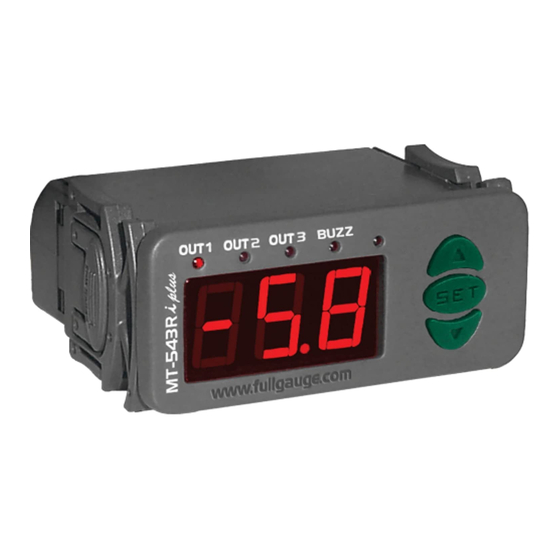
MT-543Ri plus
THREE OUTPUT DIGITAL CONTROLLER
WITH ALARM, CYCLICAL TIMER AND
SERIAL COMMUNICATION
Ver.04
®
Min Max
Description
-
-5.0
0
-50
-50
0.1
0
0
-50
-50
0.1
0
0
0
0
0
-50
-50
0.1
20.0
0
0
0
0
0
0
0
-50
-50
0
0
0
0
1
5. PARAMETERS DESCRIPTION
F01 - Access code: 123 ( one hundred and twenty-three)
To change the parameters is necessary use the access code. It is not necessary to use the access code
to visualize the adjusted parameters.
F02 - Offset indication
It allows to compensate eventual shunting lines in the reading of ambient temperature proceeding from
the exchange of the sensor or cable lenght alteration.
F03 - Operation mode of first stage
0 - Refrigeration
1 - Heating
F04 - Minimum setpoint allowed to the end user (first stage)
F05 - Máximum setpoint allowed to the end user (first stage)
Electronic limits whose purpose is prevent that too high or too low setpoint temperatures are regulated.
F06 - Control differential (hysteresis) of first stage
It is the difference of temperature(hysteresis) between turn ON and turn OFF the OUT1 output.
F07- Minimum delay to turn on the first stage output
It is the minimum time that OUT1 will keep turned off, it means, period between the last stop and the next
start.
F08 - Operation mode of second stage
0 - Refrigeration
1 - Heating
2 - Intra-range alarm (F09 and F10)
3 - Extra-range alarm (F09 and F10)
4 - Relative extra-range to first stage (
values of F09 and F10).
F09 - Minimum setpoint allowed to the end user (second stage)
F10 - Maximum setpoint allowed to the end user (second stage)
Electronic limits whose purpose is prevent that too high or too low setpoint temperatures are regulated.
When the second stage ( F08 ) is defined as alarm, the acting points are defined in F09 and F10.
NTC
CELSIUS
FAHRENHEIT
Unit
Standard
Min Max
Unit
Standard
-
-
-
-
-
-
-
°C
0
-9
9
°F
0
5.0
-
1
-
1
1
0
1
°C
-50
°F
-58
105
-58
221
°C
105
°F
221
105
-58
221
°F
°C
1.0
1
36
2
20.0
sec.
0
0
999
sec.
0
999
-
3
0
4
-
3
4
ºC
21.0
ºF
70
105
-58
221
ºC
27.0
ºF
81
105
-58
221
ºC
ºF
20.0
1.0
1
36
2
sec.
sec.
0
0
999
0
999
min.
0
0
999
min.
0
999
min.
min.
999
999
sec.
1
sec.
1
999
0
999
sec.
1
sec.
1
999
0
999
2
-
0
0
2
-
0
105
ºC
-50
-58
221
ºF
-58
105
ºC
105
-58
221
ºF
221
ºC
1.0
1
36
ºF
2
999
sec.
0
0
999
sec.
0
1
0
0
1
-
0
-
999
5
0
999
sec.
sec.
5
999
-
0
0
999
-
0
999
-
0
0
999
-
0
4
-
0
0
4
-
0
2
-
1
0
2
-
1
105
ºC
-50
-58
221
ºF
-58
105
ºC
105
-58
221
ºF
221
999
sec.
1
0
999
sec.
1
999
sec.
1
0
999
sec.
1
min.
999
min.
0
0
999
0
999
min.
999
min.
9
-
0
0
9
-
0
247
-
1
1
247
-
1
- F09 and
PT-100
CELSIUS
FAHRENHEIT
Min Max
Unit
Standard
Min Max
Unit
Standard
-
-
-
-
-
-
-
°C
90
°F
-50
50
0
-90
-
-
0
1
1
0
1
-99
300
°C
-99
-99
572
°F
-99
300
°C
300
-99
572
°F
1
40
°C
2
1
72
°F
0
999
sec.
0
0
999
sec.
-
-
0
4
3
0
4
-99
300
ºC
21
-99
572
ºF
-99
300
ºC
27
-99
572
ºF
1
40
ºC
2
1
72
ºF
0
999
sec.
0
0
999
sec.
min.
999
min.
0
999
0
0
min.
min.
999
999
0
999
sec.
1
0
999
sec.
0
999
sec.
1
0
999
sec.
0
2
-
0
0
2
-
-99
300
ºC
-99
-99
572
ºF
-99
300
ºC
300
-99
572
ºF
1
40
ºC
2
1
72
ºF
0
999
sec.
0
0
999
sec.
-
-
0
1
0
0
1
0
999
sec.
5
0
999
sec.
0
999
-
0
0
999
-
0
999
-
0
0
999
-
0
4
-
0
0
4
-
0
2
-
1
0
2
-
-99
ºC
-99
ºF
300
-99
572
ºC
ºF
-99
300
300
-99
572
0
999
sec.
1
0
999
sec.
0
999
sec.
1
0
999
sec.
0
999
min.
0
0
999
min.
999
min.
999
min.
0
9
-
0
0
9
-
1
-
1
-
247
1
247
E251415
+ F10), It is considered the absolute
-
0
1
-99
572
4
0
3
70
81
4
0
0
1
1
0
-99
572
4
0
0
5
0
0
0
1
-99
572
1
1
0
0
1
Advertisement
Table of Contents

Related Manuals for Full Gauge Controls MT-543Ri plus


Summary of Contents for Full Gauge Controls MT-543Ri plus
- Page 1 1. DESCRIPTION 5. PARAMETERS DESCRIPTION MT-543Ri plus has three outputs of temperature control and a internal buzzer. Because of its F01 - Access code: 123 ( one hundred and twenty-three) versatility, it allows that the second stage works as alarm and the third, besides to work as cyclical timer, To change the parameters is necessary use the access code.
- Page 2 F11 - Control differential(hysteresis) of second stage F34 - Intensity of the digital filter It is the difference of temperature(hysteresis) between turn ON and turn OFF the output OUT2. This filter aims at simulating an increase of the mass of sensor , thus increasing its response time (thermal inertia).
- Page 3 Over the specifield current to contactors direct activation loads use a contactor. MT-543Ri plus MT-543RiL plus 6 - 7 115V 6 - 8 230V Note: The length of the sensor cable may be increased by the user up to 200 meters, using a PP...
Need help?
Do you have a question about the MT-543Ri plus and is the answer not in the manual?
Questions and answers