
Subscribe to Our Youtube Channel
Related Manuals for ThermoFisher Scientific HyPerforma DynaDrive


Summary of Contents for ThermoFisher Scientific HyPerforma DynaDrive
- Page 1 Service Guide | DOC0154 Single-Use Bioreactor HyPerforma DynaDrive Single-Use Bioreactor Service Guide Revision | A December 2021...
-
Page 2: Table Of Contents
Contents Contents Warnings, safety, and warranty information How to use this guide Chapter 1. DynaDrive S.U.B. overview Chapter 2. Servicing and preventive maintenance 2.1. Servicing checklists 2.2. Maintenance 2.2.1. Routine maintenance 2.2.2. Preventive maintenance Chapter 3. Replacing parts 3.1. Replacement parts and part numbers 3.2. - Page 3 Contents 3.7. Replacing the 3,000 and 5,000 L load cells 3.7.1. Required parts and tools 3.7.2. Preparation 3.7.3. Replacement procedures 3.8. Replacing the 3,000 and 5,000 L cables and coolant hoses 3.8.1. Required parts and tools 3.8.2. Preparation 3.8.3. Replacement procedures 3.9.
- Page 4 Contents Chapter 5. Troubleshooting and frequently asked questions 5.1. Hardware operation issues 5.2. Cell culture operation issues 5.3. Sparging issues 5.4. Probe and connector issues 5.5. Other issues Chapter 6. DynaDrive S.U.B. specifications Chapter 7. Regional contact information 7.1. Ordering/support contact information 7.2.
-
Page 5: Warnings, Safety, And Warranty Information
Warnings, safety, and warranty information Warnings, safety, and warranty information WARNING: Read and understand this guide before servicing the equipment. The Thermo Scientific HyPerforma DynaDrive Single-Use Bioreactor (S.U.B.) is ™ ™ designed to be operated under traditional eukaryotic cell culture conditions. A general understanding of bioreactor systems and their operation is important prior to using the system for the first time. - Page 6 The vessel should not be moved by pulling of any kind. WARNING: The Thermo Scientific HyPerforma DynaDrive S.U.B. may not be installed in a potentially explosive atmosphere as set forth in the applicable EU ATEX Directive.
- Page 7 Warnings, safety, and warranty information Warranty information Any warranties, if applicable, covering this equipment exclude: (a) normal wear and tear; (b) accident, disaster or event of force majeure; (c) your misuse, fault or negligence; (d) use of the equipment in a manner for which it was not designed; (e) causes external to the equipment such as, but not limited to, external puncturing, power failure or electrical power surges;...
-
Page 8: How To Use This Guide
DOC0149 50 L HyPerforma DynaDrive S.U.B. Quick Start Guide DOC0148 500 L HyPerforma DynaDrive S.U.B. Quick Start Guide DOC0171 3,000 and 5,000 L HyPerforma DynaDrive S.U.B. Unpacking and Setup Guide DOC0176 HyPerforma DynaDrive S.U.B. Validation Guide DOC0172 Thermo Scientific DynaDrive S.U.B. Service Guide... -
Page 9: Chapter 1. Dynadrive S.u.b. Overview
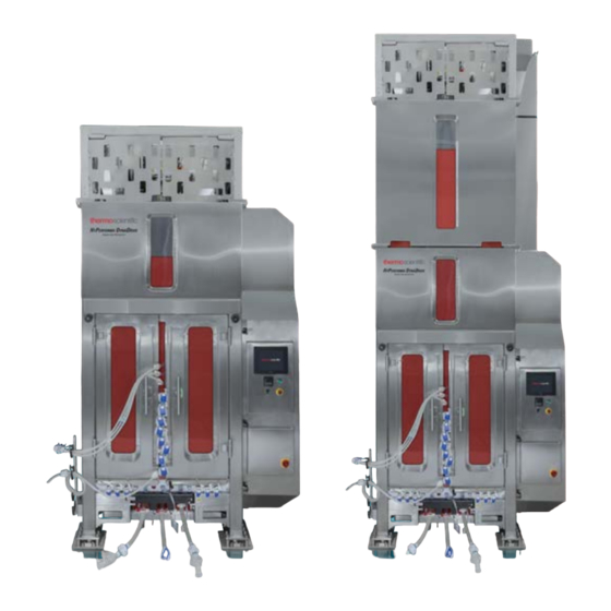
Chapter 1 | DynaDrive S.U.B. overview DynaDrive S.U.B. overview Thermo Scientific DynaDrive S.U.B. Service Guide... - Page 10 Chapter 1 | DynaDrive S.U.B. overview The Thermo Scientific HyPerforma DynaDrive Single-Use Bioreactor (S.U.B.) offers a flexible new alternative to traditional stirred-tank mixing. The system uses a redesigned impeller system: a drive train is connected to both an overhead mixing motor via a sealed bearing assembly and the bottom of the tank, allowing improved mixing while maintaining the integrity of the system.
- Page 11 Chapter 1 | DynaDrive S.U.B. overview Figures 1.3 and 1.4 illustrate the front and back views of the 500 L DynaDrive S.U.B. unit. Exhaust vent filter holder Pneumatic motor lift Agitator motor Foam probe holder BPC lift mechanism Top BPC tab Door for BPC holders loading...
- Page 12 Chapter 1 | DynaDrive S.U.B. overview Figures 1.5 and 1.6 illustrate the front and back views of the 3,000 and 5,000 L DynaDrive S.U.B. unit. BPC lift and motor (fully raised) Side panel (houses BPC lift cylinder and electrical panel) Top motor cage Touchscreen HMI (on...
-
Page 13: Chapter 2. Servicing And Preventive Maintenance
Chapter 2 | Servicing and preventive maintenance Servicing and preventive maintenance Chapter contents Servicing checklists Maintenance Thermo Scientific DynaDrive S.U.B. Service Guide... -
Page 14: Servicing Checklists
Proper tools are available (see Chapter 3). 2.2. Maintenance The following routine maintenance guidelines are based on standard operating conditions, as defined in the HyPerforma DynaDrive S.U.B. User’s Guide (DOC0090). 2.2.1. Routine maintenance Environmental conditions, operating parameters, and adhering to standard operating procedures as outlined in the user’s guide have significant impact upon the useful life... -
Page 15: Chapter 3. Replacing Parts
Chapter 3 | Replacing parts Replacing parts Chapter contents Replacement parts and part numbers Replacing the S.U.B. common-jacket drain valve and wing nut tri-clamp Replacing the 50 and 500 L quick-release pin Replacing the 50 and 500 L assembly bottom hub clamp Replacing the IMP motor, BPC lift mechanism, and hub locking mechanism Replacing the 50 and 500 L load cells... -
Page 16: Replacement Parts And Part Numbers
Chapter 3 | Replacing parts Before proceeding to perform any work on the DynaDrive S.U.B., it is mandatory to complete the following: Follow lockout/tagout procedures and local site electrical rules and laws. Verify that the assembly was completed using current Good Manufacturing Practices (cGMP). -
Page 17: Replacing The S.u.b. Common-Jacket Drain Valve And Wing Nut Tri-Clamp
Chapter 3 | Replacing parts Table 3.3. Replacement parts and part numbers for 3,000 and 5,000 L DynaDrive S.U.B.s. Components Cat. no S.U.B. Common-jacket drain valve SV51134.03 Modified tri-clamp SV51245.10 Dual 6-pin connector, 5 1/8 in. length SV50999.12 3 HP 200-230 V IPM motor, 10:1 gear SV51241.03 3,000 and 5,000 L S.U.B. -
Page 18: Replacement Procedures
Chapter 3 | Replacing parts Figure 3.1. Hanging brackets on the 500 L drain valve. 3.2.3. Replacement procedures 1. Remove the valve from the inlet/outlet port by unscrewing the wing nut until it is loose (Figure 3.2). Hold your hand under the valve as you remove the tri-clamp to catch the valve as it detaches (Figure 3.3). -
Page 19: Replacing The 50 And 500 L Quick-Release Pin
Chapter 3 | Replacing parts Note: There is a rubber seal located between the DynaDrive port and drain valve (Figure 3.4). Figure 3.4. The rubber seal that is placed between the port and drain valve. 2. Connect the new drain valve to the inlet/outlet port by holding the drain valve against the inlet/outlet port and securing it with the new tri-clamp (Figure 3.5). -
Page 20: Replacement Procedures
Chapter 3 | Replacing parts 3.3.2. Replacement procedures 1. Push the release button in the center of the quick-release pin (Figure 3.6) and pull away from the vessel to remove the pin (Figure 3.7). Figure 3.6. Pushing the release button Figure 3.7. -
Page 21: Replacing The 50 And 500 L Assembly Bottom Hub Clamp
Chapter 3 | Replacing parts 4. Push the release button in the center of the quick-release pin (Figure 3.11) and push into the vessel to replace the pin (Figure 3.12). Figure 3.11. Pushing the release button Figure 3.12. Replacing the on quick-release pin. -
Page 22: Replacing The Ipm Motor, Bpc Lift Mechanism, And Hub Locking Mechanism
Chapter 3 | Replacing parts 2. Replace with the new bottom hub clamp assembly by screwing in the four bolts using the 3/16 in. Allen wrench (Figure 3.15). Figure 3.15. Replacing the four bolts to the assembly bottom hub clamp. 3.5. - Page 23 Chapter 3 | Replacing parts Removing the motor 1. Remove the four long bolts located on the top of the motor assembly using a 1/4 in. Allen wrench (Figure 3.16). Figure 3.16. Removing one of the four bolts from the top of the motor assembly.
- Page 24 Chapter 3 | Replacing parts 4. Remove the top bolt and screw using a 5/16 in. Allen wrench located on the top of the assembly lift (Figure 3.19). Before you fully remove the bolt, you will need to hold onto the hub locking mechanism to ensure it does not fall. Note: You will need to use an adjustable wrench to loosen this top bolt.
- Page 25 Chapter 3 | Replacing parts Figure 3.21. Removing the motor from the motor assembly. Removing and replacing the 50 L BPC lift mechanism 1. Using a 5/16 in. Allen wrench, remove the four bolts located on top of the motor mount (Figure 3.22).
- Page 26 Chapter 3 | Replacing parts Figure 3.23. Loosening the bolts on top of the motor mount spacer. 3. Replace the BPC lift mechanism and the motor mount spacer using a 5/16 in. Allen wrench, replacing the four bolts that are located on top of the motor mount (Figure 3.24).
- Page 27 Chapter 3 | Replacing parts 2. Remove the 500 L BPC lift mechanism from the lift arm (Figure 3.26). Figure 3.26. Removed 500 L BPC lift mechanism. 3. Replace the BPC lift mechanism in the lift arm using a 1/4 in. Allen wrench, replacing the four bolts that are located on the lift arm (Figure 3.27).
- Page 28 Chapter 3 | Replacing parts Figure 3.28. Replacing the motor from the motor assembly. 2. Replace the hub locking mechanism by sliding the bottom of the hub locking mechanism into the the bottom of the motor assembly (Figure 3.29) and sliding the top of the hub locking mechanism into the top of the motor assembly (Figure 3.30).
- Page 29 Chapter 3 | Replacing parts Figure 3.31. Securing the bolt on top of the assembly lift. 4. Replace the top plate of the motor assembly (Figure 3.32). 5. Secure the top two bolts on both sides of the motor assembly using a 5/32 in. Allen wrench (Figure 3.33).
-
Page 30: Replacing The 50 And 500 L Load Cells
Chapter 3 | Replacing parts 3.6. Replacing the 50 and 500 L load cells Use the following instructions to replace the load cells and rerouting the wires back into the cart and into the summing block. It is recommended to replace one load cell at a time. - Page 31 Chapter 3 | Replacing parts Figure 3.36. Loosening a bolt securing a load cell to a leg. 3. Twist the load cell lock-out nut clockwise (approximately 6 mm (0.24 in.)) to relieve the pressure from the weight of the DynaDrive unit (Figure 3.37). Figure 3.37.
- Page 32 Chapter 3 | Replacing parts 5. Remove the cable wires from the summing block. Note: Make sure to make note of where the wires are connected before removing (Figure 3.39). TO LOAD CELL 2 Note: Do not cut load cell cables to length. Use original cable and length provided from vendor.
-
Page 33: Replacement Procedures
Chapter 3 | Replacing parts 7. Attach a cable router to the end of each of the cables before removing to allow you to more easily replace the new cables. 8. Remove the load cell cables from the summing block if it is a standalone unit. - Page 34 Chapter 3 | Replacing parts 2. Use a flathead screwdriver to tighten each screw to secure each wire (Figure 3.43). Figure 3.43. Tightening the screw to secure the wire into place. 3. Cover the wiring with the plastic tubing and screw the end to secure the plastic piece to pin-out connector (Figures 3.44 and 3.45).
- Page 35 Chapter 3 | Replacing parts Figure 3.46. Sliding plastic piece up Figure 3.47. Screwing the last plastic to tubing. piece to the tubing. Rewiring the load cells for vessels with an E-Box Important: Wires are calibrated by Mettler Toledo, and cannot be tampered with.
- Page 36 Chapter 3 | Replacing parts TO LOAD CELL 2 Note: Do not cut load cell cables to length. Use original cable and length provided from vendor. All cables must be the same length. Mettler Toledo Summing Block WHITE +EXE +EXE YELLOW +SEN +SEN...
- Page 37 Chapter 3 | Replacing parts 4. Feed the summing block cable through the center liquid tight fitting to the summing block (see Figure 3.50) and attach wires according to the wire schematic in Figure 3.49. 5. Coil up excess load cell wire length into the cart body and reattach the summing block and summing block plate to the cart.
- Page 38 Chapter 3 | Replacing parts 3. Fasten the load cell using a 3/16 in. Allen wrench with the two bolts (Figure 3.53). Note: Make sure the arrow on the load cell is pointing down. Two 3/16 in. bolts Figure 3.53. Bolts on top of the load cell. 4.
-
Page 39: Replacing The 3,000 And 5,000 L Load Cells
Chapter 3 | Replacing parts 3.7. Replacing the 3,000 and 5,000 L load cells Use the following instructions to replace the load cells and rerouting the wires back into the cart and into the summing block. See Tables 3.1–3.3 for part numbers based on your system size. - Page 40 Chapter 3 | Replacing parts LOAD CELL LOAD CELL TRN1 SUM BLOCK -EXC -EXC CN37 -SEN -SEN CN37-1/TN1--EXC CN37-2/TN1--SEN -SIG -SIG CN37-3/TN1--SIG SHIELD SHIELD CN37-4/TN1-SHLD CN37-5/TN1-+SIG +SIG +SIG CN37-6/TN1-+SEN +SEN +SEN CN37-7/TN1-+EXC +EXC +EXC LOAD CELL LOAD CELL Figure 3.57. Wiring diagram showing connections from the load cell cables to the summing block. 3.
-
Page 41: Replacement Procedures
Chapter 3 | Replacing parts 3.7.3. Replacement procedures 1. Using a 5/32 in. Allen wrench, remove each foot cover by removing the four bolts (two on each side) (Figure 3.59). Figure 3.59. Two bolts on the foot cover. 2. Use a hydraulic lift to raise the 3,000 or 5,000 L DynaDrive unit by 1 mm. 3. -
Page 42: Replacing The 3,000 And 5,000 L Cables And Coolant Hoses
Chapter 3 | Replacing parts 3.8. Replacing the 3,000 and 5,000 L cables and coolant hoses Use the following instructions to replace the cables and coolant hoses for 3,000 and 5,000 L DynaDrive systems. 3.8.1. Required parts and tools Spare cables (part numbers SV51246.04, SV51246.05, and SV51246.06) •... -
Page 43: Preparation
Chapter 3 | Replacing parts 3.9.2. Preparation 1. Lower the platform completely. 2. Open the HMI control box and remove the plate that covers the pneumatic valves with an 1/8 in. Allen wrench (Figure 3.61). Figure 3.61. Removing the plate that covers the large valve. 3. - Page 44 Chapter 3 | Replacing parts 2. Pull pin out to remove the end of the cables (Figures 3.64 and 3.65). Figure 3.64. Removing the pin from the Figure 3.65. Removing the end of the pulley assembly. cables from the pulley assembly. Note: It is recommended to replace each pulley one at a time to make it easier to replace the cables correctly.
- Page 45 Chapter 3 | Replacing parts Figure 3.69. Replacing the back spacer and pulley. 5. Align the pulley and spacers in the pulley assembly space (Figure 3.70). Note: Make sure the cables are in the correct cable grooves and are aligned correctly. Figure 3.70.
-
Page 46: Replacement Procedures For Pulley Cables
Chapter 3 | Replacing parts Notes: It is recommended to remove and replace one pulley at a time. • To re-tighten the cables, it is recommended to manually lift the platform using • the large valve button (located in the HMI fuse box) to ensure the cables are aligned properly. -
Page 47: Replacing The 3,000 And 5,000 L Bpc Lift Cylinder
Chapter 3 | Replacing parts 3.10. Replacing the 3,000 and 5,000 L BPC lift cylinder Use the following instructions to replace the BPC lift cylinder for 3,000 and 5,000 L DynaDrive systems. 3.10.1. Required parts and tools Spare BPC lift cylinder (part number SV51245.08) •... - Page 48 Chapter 3 | Replacing parts 2. Using a pair of pliers, locate and remove the locking pin attached to the locking cylinder arm and platform locking mechanism (Figure 3.74). Figure 3.74. Removing locking pin from locking cylinder arm. 3. Remove pin holding the locking cylinder and locking mechanism platform together. Push the locking cylinder to the side (Figure 3.75).
-
Page 49: Replacement Procedures
Chapter 3 | Replacing parts 3.11.3. Replacement procedures 1. Using a 3/8 in. Allen wrench, remove the three bolts holding the locking mechanism platform in place (Figure 3.78). Figure 3.78. Removing bolts from the locking mechanism platform. 2. Remove the platform locking mechanism. Replace with new platform locking mechanism. -
Page 50: Replacing The 3,000 And 5,000 L Assembly Bottom Hub Clamp
Chapter 3 | Replacing parts Figure 3.80. Replace pin to locking cylinder arm and locking mechanism platform. 6. Using a pair of pliers, insert the locking pin into the pin locking cylinder arm and platform locking mechanism and re-position the locking pin (Figure 3.81). Figure 3.81. -
Page 51: Replacing The 3,000 And 5,000 L Condenser Heater
Chapter 3 | Replacing parts Figure 3.82. Removing one of six bolts from bottom hub clamp assembly. 2. Replace with the new bottom hub clamp assembly by screwing in the six bolts using the 7/32 in. Allen wrench (Figure 3.83). Figure 3.83. -
Page 52: Replacement Procedures
Chapter 3 | Replacing parts 3.13.3. Replacement procedures 1. Press in the button that releases the lock pin, then pull out the lock pin (Figure 3.84). Figure 3.84. Removing the lock pin. 2. Unplug the condenser heater from the variable frequency drive (VFD) electrical box from the filter heater ports (Figure 3.85). - Page 53 Chapter 3 | Replacing parts 3. Pull the condenser heater towards you off of the heater mount (Figure 3.86). Figure 3.86. Removing the condenser heater from the heater mount. 4. Replace with the new condenser heater by sliding the heater onto the heater mount (Figure 3.87).
- Page 54 Chapter 3 | Replacing parts Filter heater ports Figure 3.88. VFD electrical box and filter heater ports. 6. Replace lock pin (Figure 3.89). Figure 3.89. Replacing the lock pin. Thermo Scientific DynaDrive S.U.B. Service Guide...
-
Page 55: Additional Replacement Parts And Part Numbers
Chapter 3 | Replacing parts 3.14. Additional replacement parts and part numbers The following table lists part numbers for replacing additional DynaDrive S.U.B. system components. Table 3.5. Additional replacement parts and part numbers. Components Cat. no 50 L S.U.B. cable management system SV50992.01 500 L S.U.B. -
Page 56: Installing Foam Probe Holder
Chapter 3 | Replacing parts 3.14.2. Installing foam probe holder 1. Snap or slide the foam probe holder into place on the left side of the top rim of the unit. 2. Adjust location as needed to ensure alignment with the foam probe tube (Figures 3.91–3.93). - Page 57 Chapter 3 | Replacing parts Figure 3.96. BPC tab holder in place. 3. Pull each BPC tab up in front of the tab holder, and then push the tab onto the tab holder sphere to secure the BPC in place (Figures 3.97 and 3.98). Figure 3.97.
-
Page 58: Chapter 4. Recommended Spare Part Inventory
Chapter 4 | Recommended spare part inventory Recommended spare part inventory Thermo Scientific DynaDrive S.U.B. Service Guide... - Page 59 Chapter 4 | Recommended spare part inventory Spare part inventory of each customer should be based on failure risk. The following tables list part numbers for additional DynaDrive S.U.B. system components, such as load cell kits and accessories. Table 4.1. Harsh mount load cell display part numbers for 50 and 500 L systems using the Thermo Scientific E-Box.
- Page 60 Chapter 4 | Recommended spare part inventory Table 4.4. Vent filter heater kit part numbers for use with Pall KA3 vent filters. Includes vent filter heater, controller with water-tight closure, quick-connects, and installation power cord. Components Cat. no NEMA rated vent heater with programmable controller (100–120 VAC), power cord.
- Page 61 Chapter 4 | Recommended spare part inventory Table 4.7. Miscellaneous and accessory part numbers. Components Cat. no Probe assembly with CPC AseptiQuik connector (non-sterile, for SH30720.02 use in autoclave) Probe assembly with Pall Kleenpak connector (non-sterile, for use SH30720.01 in autoclave) Heavy-duty tubing clamp—single SV20664.01 Heavy-duty tubing clamp—pack of 10...
-
Page 62: Chapter 5. Troubleshooting And Frequently Asked Questions
Chapter 5 | Troubleshooting and frequently asked questions Troubleshooting and frequently asked questions Chapter contents Hardware operation issues Cell culture operation issues Sparging issues Probe and connector issues Other issues Thermo Scientific DynaDrive S.U.B. Service Guide... -
Page 63: Hardware Operation Issues
Chapter 5 | Troubleshooting and frequently asked questions 5.1. Hardware operation issues Issue: The DynaDrive S.U.B. will not operate. Solutions: Check the power supply. Verify the position of the main electrical plug connection at the wall outlet, the main • power disconnect, and the emergency stop switch. -
Page 64: Cell Culture Operation Issues
Chapter 5 | Troubleshooting and frequently asked questions Issue: I typically use level sensors to control the volume and feed rate or supplement during a bioreactor run; how would I do this with the DynaDrive S.U.B.? Solution: Use load cells or a scale to control volumes based upon weight. The DynaDrive S.U.B. -
Page 65: Sparging Issues
Chapter 5 | Troubleshooting and frequently asked questions Issue: We are not achieving the cell growth we expected in the DynaDrive S.U.B. while running under our normal bioreactor agitation and sparging rates. What should we do? Solutions: Reduce agitation and sparging rates. Often low cell viability and cell growth can be attributed to excessive sparging or •... -
Page 66: Probe And Connector Issues
Chapter 5 | Troubleshooting and frequently asked questions 5.4. Probe and connector issues Issue: We forgot to introduce the pH and DO probes prior to media fill; can we still make a sterile connection under these conditions? Solutions: Yes, as long as the clamps were closed on the aseptic connector probe ports before liquid fill. -
Page 67: Chapter 6. Dynadrive S.u.b. Specifications
Chapter 6 | DynaDrive S.U.B. specifications DynaDrive S.U.B. specifications Thermo Scientific DynaDrive S.U.B. Service Guide... - Page 68 Chapter 6 | DynaDrive S.U.B. specifications Table 6.1. 50 L DynaDrive S.U.B. specifications. Specification Bioreactor geometry Rated liquid working volume 50 L Minimum liquid working volume Total reactor volume (liquid & gas) 66 L BPC chamber diameter 29 cm (12 in.) BPC chamber shoulder height 102 cm (40 in.) Liquid height at rated working volume...
- Page 69 Chapter 6 | DynaDrive S.U.B. specifications Table 6.2. 50 L DynaDrive S.U.B. specifications (continued). Specification Support container 103 cm (41 in.) with optional E-Box Overall width 69 cm (27 in.) without E-Box Overall length 77 cm (30 in.) Overall height 178 cm (70 in.) 236 kg (519 lb.) with optional E-Box Dry skid weight (mass)
- Page 70 Chapter 6 | DynaDrive S.U.B. specifications Table 6.3. 500 L DynaDrive S.U.B. specifications. Specification Bioreactor geometry Rated liquid working volume 500 L Minimum liquid working volume 25 L Total reactor volume (liquid & gas) 586 L BPC chamber diameter 63 cm (25 in.) BPC chamber shoulder height 187 cm (74 in.) Liquid height inside tank at rated working volume...
- Page 71 Chapter 6 | DynaDrive S.U.B. specifications Table 6.4. 500 L DynaDrive S.U.B. specifications (continued). Specification Support container 141 cm (56 in.) with optional E-Box Overall width 103 cm (41 in.) without E-Box Overall length 101 cm (40 in.) Overall height 311 cm (122 in.) 522 kg (1,151 lb.) with optional E-Box Dry skid weight (mass)
- Page 72 Chapter 6 | DynaDrive S.U.B. specifications Table 6.5. 3,000 and 5,000 L DynaDrive S.U.B. specifications. 3,000 L 5,000 L Bioreactor geometry Rated liquid working volume 3,000 L 5,000 L Minimum liquid working volume 250 L 250 L Total reactor volume (liquid & gas) 3,730 L 5,585 L BPC chamber diameter...
- Page 73 Chapter 6 | DynaDrive S.U.B. specifications Table 6.6. 3,000 and 5,000 L DynaDrive S.U.B. specifications (continued). 3,000 L 5,000 L Support container Overall width 228 cm (90 in.) Overall length 164 cm (65 in.) Overall height 345 cm (136 in.) 486 cm (192 in.) Dry skid weight (mass) 2,525 kg (5,566 lb)
-
Page 74: Chapter 7. Regional Contact Information
Chapter 7 | Regional contact information Regional contact information Chapter contents Ordering/support contact information Technical support Thermo Scientific DynaDrive S.U.B. Service Guide... -
Page 75: Ordering/Support Contact Information
Chapter 7 | Regional contact information 7.1. Ordering/support contact information In the Americas and Asia 1726 Hyclone Drive Logan, Utah 84321 United States Tel: +1 435 792 8500 Email: customerservice.bioprocessing@thermofisher.com In Europe Unit 9 Atley Way Cramlington, NE 23 1WA Great Britain Tel: +44 (0) 1670 734093 Fax: +44 (0) 1670 732537... - Page 76 Learn more at thermofisher.com/dynadrive For Research Use or Further Manufacturing. Not for diagnostic use or direct administration into humans or animals. © 2021 Thermo Fisher Scientific Inc. All rights reserved. All trademarks are the property of Thermo Fisher Scientific and its subsidiaries unless otherwise specified.
Need help?
Do you have a question about the HyPerforma DynaDrive and is the answer not in the manual?
Questions and answers