
Related Manuals for ThermoFisher Scientific Thermo Scientific IMP 180


Summary of Contents for ThermoFisher Scientific Thermo Scientific IMP 180
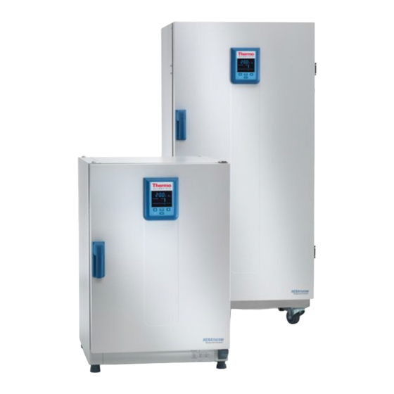
- Page 1 IMP 180 / IMP 400 Heratherm Refrigerated Incubators Operating Instructions 50150875 • Revision D • September 2022...
- Page 2 © Thermo Fisher Scientific Inc. All rights reserved. Thermo Fisher Scientific Inc. provides this document to its customers with a product purchase to use in the product operation. This document is copyright protected and any reproduction of the whole or any part of this document is strictly prohibited, except with the written authorization of Thermo Fisher Scientific Inc.
-
Page 3: Table Of Contents
Contents Chapter 1 Safety Notes ........................1-1 Basic Operating Precautions ....................... 1-1 Operational Safety Rules ........................1-2 Warranty ............................1-2 Explanation of Safety Information and Symbols ................. 1-3 Safety Notes and Symbols Used Throughout These Operating Instructions ........1-3 Additional Symbols for Safety Information..................1-4 Symbols on the refrigerated incubator .................... - Page 4 Contents AC Power Socket..........................4-9 Fuses............................... 4-9 Work Space Components ......................... 4-11 Inner Chamber ..........................4-11 Access Port ........................... 4-11 Additional Tube Access Ports (Option) .................... 4-13 Chapter 5 Installation procedures ....................5-1 Table-top refrigerated incubators......................5-1 Installing the Shelf System........................5-1 Initial Installation ...........................
- Page 5 Contents Program Preferences ........................7-22 Configuration..........................7-25 Programming ............................7-26 End of Program..........................7-26 Instructions ...........................7-26 Chapter 8 Shut-down .........................8-1 Shutting the refrigerated incubator down ....................8-1 Chapter 9 Cleaning and Disinfection ....................9-1 Cleaning..............................9-1 Cleaning Exterior Surfaces.......................9-1 Wipe / Spray Disinfection ........................9-1 Preparing the Manual Wipe/Spray Disinfection ................9-3 Predisinfection ..........................9-3 Cleaning............................9-4 Final Disinfection..........................9-4...
- Page 6 Contents Heratherm IMP Thermo Scientific...
- Page 7 List of Figures Figure 3-1 Table-top refrigerated incubators, dimensions and required clearances ..........3-3 Figure 3-2 Floor stand refrigerated incubators, dimensions and required clearances ..........3-4 Figure 3-3 Lift Points............................. 3-5 Figure 4-1 Heratherm IMP 180 Front View ......................4-2 Figure 4-2 Heratherm IMP 180 Rear View......................
- Page 8 List of Figures Heratherm IMP Thermo Scientific...
-
Page 9: Chapter 1 Safety Notes
Safety Notes Basic Operating Precautions These operating instructions describe Heratherm refrigerated incubators. Heratherm refrigerated incubators have been manufactured to the latest state of the art and have been tested thoroughly for flawless functioning prior to shipping. However, the refrigerated incubator may present potential hazards, particularly if it is operated by inadequately trained personnel or if it is not used in accordance with the intended purpose. -
Page 10: Operational Safety Rules
Safety Notes Operational Safety Rules • Should you encounter problems that are not detailed adequately in these operating instructions, please contact Thermo Electron LED GmbH immediately for your own safety. Operational Safety Rules The following rules must be heeded when working with Heratherm refrigerated incubators: •... -
Page 11: Explanation Of Safety Information And Symbols
Safety Notes Explanation of Safety Information and Symbols Explanation of Safety Information and Symbols Safety Notes and Symbols Used Throughout These Operating Instructions Indicates a hazardous situation which, if not avoided, will result in death or serious injuries. Indicates a hazardous situation which, if not avoided, could result in death or serious injuries. -
Page 12: Additional Symbols For Safety Information
Safety Notes Explanation of Safety Information and Symbols Additional Symbols for Safety Information Wear safety gloves! Wear safety goggles! Harmful liquids! Electric shock! Hot surfaces! Fire hazard! Explosion hazard! Suffocation hazard! Biological hazard! Contamination hazard! Danger of tipping! Heratherm IMP Thermo Scientific... -
Page 13: Symbols On The Refrigerated Incubator
Safety Notes Explanation of Safety Information and Symbols Symbols on the refrigerated incubator Observe operating instructions 120 Volts AC power socket 230 Volts AC power socket Alarm contact Fuse 2 A, slow blow, high breaking current, 250 volt Hot surfaces! EAC conformity mark: confirms conformity according to all technical regula- tions of the Eurasian customs union (Russia, Kazakhstan and Belarus) RS 232 interface... -
Page 14: Intended Purpose
Safety Notes Intended Purpose Intended Purpose Intended Purpose of the refrigerated incubator Heratherm refrigerated incubators are laboratory equipment for tempering (cooling and heating) of defined substances and materials. They serve for the preparation and cultivation of cell and tissue cultures. The devices employ precision temperature control for simulating the particular physiological environment for these cultures. - Page 15 Safety Notes Standards and Directives Note: This equipment has been tested and found to comply with the limits for a Class A digital device, pursuant to part 15 of the FCC Rules. These limits are designed to provide reasonable protection against harmful interference when the equipment is operated in a commercial environment. This equipment generates, uses, and can radiate radio frequency energy and, if not installed and used in accordance with the instruction manual, may cause harmful interference to radio communications.
- Page 16 Safety Notes Standards and Directives Heratherm IMP Thermo Scientific...
-
Page 17: Chapter 2 Delivery Of The Refrigerated Incubator
Delivery of the refrigerated incubator Packaging Heratherm refrigerated incubators are delivered in a rugged packaging box. All packaging materials can be separated and are reusable: Packaging materials Packaging carton: Recycled paper Foam elements: Styrofoam (CFC-free and HFC-free) Pallet: Chemically untreated wood Packaging film: Polyethylene Packaging ribbons:... -
Page 18: Scope Of Supply
Delivery of the refrigerated incubator Scope of Supply Scope of Supply Refrigerated Incubators Quantity of components supplied (pieces) IMP Series Perforated shelves Support rail for shelf table-top refrigerated incubators Shelf support Power cord Connector, potential-free contact Clip springs for table-top refrigerated incubators Plug for standard access port Anti-tilt anchor Operating manual... -
Page 19: Chapter 3 Installation
Installation Ambient Conditions Location Requirements The refrigerated incubator must only be operated in a location that meets all of the ambient condition requirements listed below: • Installation location indoors in dry areas free from drafts. • The dust burden may not exceed the contamination category 2 based on EN 61010-1. Using the refrigerated incubator in an atmosphere with electrically conductive dust is prohibited. -
Page 20: Intermediate Storage
Installation Intermediate Storage • Relative humidity up to 70%, non condensing, at an ambient temperature of 28°C. • Should condensation exist, wait until the moisture has evaporated completely before connecting the refrigerated incubator to a power source and powering up. Humidity After transport or storing under humid conditions a drying-out process must be performed. -
Page 21: Space Requirement
Installation Room Ventilation Space Requirement When installing the refrigerated incubator, make sure that the installation and supply connections remain freely accessible. The specified side clearances represent minimum distances. Table-top refrigerated incubators Figure 3-1 Table-top refrigerated incubators, dimensions and required clearances Table 3-1 refrigerated incubator Dimensions Model A (mm/inch) -
Page 22: Floor Stand Refrigerated Incubators
Installation Room Ventilation Floor Stand refrigerated incubators 400 liter units Figure 3-2 Floor stand refrigerated incubators, dimensions and required clearances Model A (mm/inch) B (mm/inch) C (mm/inch) D (mm/inch) IMP 400 755/29.7 770/30.3 1655/65.2 810/31.9 * Depth of handle /display (66 mm/2.6 in) not included in overall depth specified. Width of hinge (23 mm/0,91 in) not included in overall width. -
Page 23: Transport
Installation Transport Transport Humidity After transport or storing under humid conditions a drying-out process must be performed. During the drying-out process the equipment cannot be assumed to meet all the safety requirements of the IEC 61010-2-010 standard. The drying-out period is 2 hours. Table-top refrigerated incubators For transport, do not lift the refrigerated incubator using the doors or components attached to the refrigerated incubator as lift points. - Page 24 Installation Transport Floor stand refrigerated incubators The floor stand refrigerated incubators come equipped with four (4) casters. The lever for releasing the caster is located above the locking lever. After positioning the unit in its installation location ensure that the locking levers are pressed down on the casters. To ensure the degree of stability specified by safety requirements the front casters must be turned so that they are facing forward after the unit has been positioned in its installation location and the locking levers pressed down on these casters.
-
Page 25: Stacking Table-Top Units
Installation Stacking Table-Top Units Stacking Table-Top Units Two IMP 180 can be stacked without use of a stacking kit. The kit is recommended when stacking with an oven or a unit with decontamination cycle, to avoid temperature impact. 2 x Anti-tilt anchor Stacking Adapter Two IMP 180 can be stacked without stacking adapter.A stacking adapter kit is recommended when an oven or a unit with decontamination routine is stacked to avoid... -
Page 26: Installing The Anti-Tilt Anchor
Installation Installing the Anti-tilt Anchor Installing the Anti-tilt Anchor Table-top refrigerated incubators The Heratherm table-top refrigerated incubators must be secured with anti-tilt anchors witch are connected a solid part of a building. The anti-tilt anchor is to be mounted in the middle position (2) or if not possible on the side opposite of the door hinges. - Page 27 Installation Installing the Anti-tilt Anchor Floor stand refrigerated incubators Heratherm floor stand refrigerated incubators must always be attached to the wall using two (2) retaining brackets on the outer left and right side on the back of the unit. When operating under maximum environment- and condition of employment and when using low setpoint temperature can lead to performance losses in stacked devices.
- Page 28 Installation Installing the Anti-tilt Anchor Additionally, the following caution notes must be heeded at all times: Risk of overheating with stacked devices To avoid the risk of electrical components and the outer enclosure overheating or temperature control failing due to insufficient ventilation, do not exceed the specified stacking height! Risk of tipping and dropping of stacked devices You should be aware at all times that stacked devices do not form a stable unit,...
-
Page 29: Chapter 4 Product Description
Product Description Heratherm IMP Series refrigerated incubator Overview IMP Series refrigerated incubators come equipped with the following features: • high-precision work space temperature control, adjustable in steps of one-tenth of a degree from 5°C (32°F) up to 70°C (158°F) • Peltier-air-air-system with work space and outside fan •... -
Page 30: Figure 4-1 Heratherm Imp 180 Front View
Product Description Heratherm IMP Series refrigerated incubator Overview The individual features of IMP Series refrigerated incubators are shown in the figures below. Figure 4-1 Heratherm IMP 180 Front View Outer door Door latch cutout Door latch and handle Door hinge, lower Leveling foot Nameplate Temperature sensor... -
Page 31: Figure 4-2 Heratherm Imp 180 Rear View
Product Description Heratherm IMP Series refrigerated incubator Overview Figure 4-2 Heratherm IMP 180 Rear View Door latch and handle Control panel Stacking pad Access port Peltier system with outside fan Electronics compartment Leveling foot Condense water drain with dish [10] Electro compartment Condensate water dish Prior to the commisioning of the unit the condensate water dish is to be installed according to figure 4-2. -
Page 32: Figure 4-3 Heratherm Imp 400 Front View
Product Description Heratherm IMP Series refrigerated incubator Overview Figure 4-3 Heratherm IMP 400 Front View Outer door Door latch Unit caster Air baffle Perforated shelf Door hook catch Glass door latch Temperature sensor Access port [10] Glass door [11] Fan opening, air baffle [12] Door frame heater Heratherm IMP Thermo Scientific... -
Page 33: Figure 4-4 Heratherm Imp 400 Rear View
Product Description Heratherm IMP Series refrigerated incubator Overview Figure 4-4 Heratherm IMP 400 Rear View Outer door Unit caster 2 x condensate water drain with dish Access port Anti-tilt anchor Electronics compartment Hinge Door handle Display [10] Nameplate on sidewall [11] 2 x Peltier system with outside fan Condensate water dish Prior to the commisioning of the unit the both condensate water dishes... -
Page 34: Peltier System
Product Description Peltier System Peltier System The installed "Peltier -air-air system" (see Figure 4-5 and 4-6) is integrated in the rear wall and designed for tempering (cooling and heating) of the usable space. The Peltier module consists of two heat sinks (heat exchanger), each equipped with an axial fan. In cooling mode, heat from the usable space is absorbed and conducted to the environment on the device outside. -
Page 35: Safety Devices
Product Description Safety Devices Hot surface! The Peltier system at the rear side of the incubator can be hot as far as 120 °C (248 °F) in event of a malfunction. Only with heat resisted gloves the rear side of the incubator should then be accessed. - Page 36 Product Description Sensing and Control System Figure 4-7 PT100 Sensor IMP 180 Figure 4-8 PT100 Sensor IMP 400 The work space temperature sensor provides the inputs to the refrigerated incubator’s built-in controller, which continuously compares the measured values to the user-specified set value and adjusts the heaters according to the result.
-
Page 37: Data Communications & Alarm Interface
Product Description Data Communications & Alarm Interface Data Communications & Alarm Interface All signal connections are installed in the electrical interface panel at the rear of the refrigerated incubator. RS-232 Interface The RS- 232 interface (item 2 in figure 4-9 below) may be used to connect Heratherm refrigerated incubators to the serial interface port of a computer to allow for the computer-aided acquisition and documentation of major operating parameters (temperature,... -
Page 38: Figure 4-10 T 2A H 250V Fuse
Product Description Data Communications & Alarm Interface Replacement should only be carried out by skilled and authorized qualified personnel of electrotechnology/signal engineering! Fuse replacement 15 A fuses The device fuses are not user-serviceable. When the refrigerated incubator exhibits the typical signs of a blown fuse (no response to pressing the On/Off button, control panel remains extinguished, no heating operation), call Thermo Fisher Scientific Customer Service to have the fuses replaced. -
Page 39: Work Space Components
Product Description Work Space Components Work Space Components Inner Chamber All components of the work space are made of corrosion-resistant stainless steel and have an absolutely smooth and easy-to-clean surface. Any embossings have a large radius. Access Port A re-sealable, capped access port (can be closed off using the plugs delivered with the unit) allows cables, hoses or additional sensor leads to be routed into the work space of the refrigerated incubator. -
Page 40: Figure 4-12 Shelf System
Product Description Work Space Components Shelf System The refrigerated incubator is supplied with two perforated shelves. The shelf support rails [1] have an alternating pattern of oblong and round perforations spaced evenly at 30 mm, allowing the shelf support brackets [8] to be inserted without any room for error, yet in a very flexible way to accommodate any required height of sample container. -
Page 41: Additional Tube Access Ports (Option)
Product Description Additional Tube Access Ports (Option) Additional Tube Access Ports (Option) Heratherm refrigerated incubators may be equipped with additional tube access ports in the side and top panels. Available tube access port options are listed in table 4-1 below. Tabelle 4-1 Tube Access Ports for Heratherm refrigerated incubators (Option) Side Panel Mounted Port, Top Panel Mounted Port,... - Page 42 Product Description Additional Tube Access Ports (Option) 4-14 Heratherm IMP Thermo Scientific...
-
Page 43: Chapter 5 Installation Procedures
Installation procedures Table-top refrigerated incubators Installing the Shelf System The installation of the shelf system does not require any tools. The support rails are secured in place by spring action. Once the shelf support brackets have been inserted into the rails, the perforated shelves can be simply pushed onto their support hooks to complete the installation. -
Page 44: Installing The Perforated Shelves
Installation procedures Installing the Perforated Shelves Installing the Perforated Shelves The illustration below shows the placement of the shelf system elements. Air Baffles Retaining Springs (only for table-top refrigerated incubators) Support Rails Shelf Support Shelves Figure 5-2 Installing the Shelving Preparing the usable space Upon delivery, Heratherm refrigerated incubators are not in a sterile state. -
Page 45: Installation Or Removal Of The Support Rails
Installation procedures Preparing the usable space Cleaning and disinfection For details about the cleaning and disinfection of the refrigerated “Cleaning” incubator, please refer to page 9-1. Installation or Removal of the Support Rails Figure 5-3 Support Rail Installation The embossings at [2] and [5] act as lateral guides for the support rails, while the embossings at [1] and [6] secure the support rails in place. -
Page 46: Installing And Uninstalling The Air Baffle
Installation procedures Preparing the usable space Installing and Uninstalling the Air Baffle Heratherm IMP Series refrigerated incubators are shipped from the factory with the air baffle readily pre-installed. Before the air baffle can be removed from the back wall, the support rails need to uninstalled. -
Page 47: Commissioning Of Floor Stand Refrigerated Incubators
Installation procedures Commissioning of floor stand refrigerated incubators Commissioning of floor stand refrigerated incubators Installing/Removing air baffles (IMP 400 Series) The section below describes how to install/remove the bottom plate. Figure 5-5 Removing the bottom plate 1. Loosen and remove the four (4) screws in the bottom plate and then remove the bottom plate completely. -
Page 48: Commissioning, General
Installation procedures Commissioning, general Commissioning, general Installing the Shelf Support Brackets 1. Insert the shelf support bracket [3] into the perforations [1] of the support rail and tilt it downwards. 2. Make sure that the two vertical elements [2] of the shelf support bracket butt against the support rail. -
Page 49: Mains Connection
Installation procedures Mains connection 2. Slightly raise the perforated shelf so that the pull-out stops [1] and [3] can slide over the shelf support brackets. 3. Make sure that the shelves and both of their tilt protection devices are free to move over the shelf support brackets. -
Page 50: Connecting The Rs-232 Interface
Installation procedures Connecting the RS-232 Interface Keep the power outlet accessible! To allow a rapid disconnection of power in case of an emergency, make sure that power outlets remain freely accessible at all times! Figure 5-9 AC Power Supply Socket Condensation When taking the refrigerated incubator into operation for the first time allow some time before switching on for stabilization to avoid... -
Page 51: Interconnecting The Refrigerated Incubator With A Computer
Installation procedures Connecting the RS-232 Interface Users may employ the RS-232 command inventory listed in table 5-1 below for automating process data logging - for example, by embedding these commands in scripts that run on a remote computer. RS-232 interface compatibility To avoid overloading and damaging the RS-232 interface check the interfacing parameters against the pin-out description given above and make sure that computer’s interface port works with a signal level of +/-... - Page 52 Installation procedures Connecting the RS-232 Interface — bb:: is a query, that must be left at „00” for technical reasons; — cc is for a command - specific checksum listed in the table below. — <CR> is for carriage return. You will receive a response of the following general format: !:aaaa:bb:XXXXX:cc<CR>...
-
Page 53: Wiring The Alarm Contact
Installation procedures Wiring the Alarm Contact Wiring the Alarm Contact Skilled work Thermo Scientific warrants the operational safety and the operativeness of the refrigerated incubator only if installation and repairs are performed by skilled personnel. The connection of the refrigerated incubator to an external alarm system must only be carried out by adequately trained and authorized electrical engineering or telecommunications expert personnel! Functional Description... -
Page 54: Connection Example
Installation procedures Wiring the Alarm Contact Connection Example The connector [5] for the interface cable is supplied with the refrigerated incubator as a standard item. Specifications for the operating voltage and the fusing of external alarm circuitry are given in the table above. 1. -
Page 55: Chapter 6 Operation
Operation Preparing the refrigerated incubator The refrigerated incubator must not be released for operation before all major start-up activities have been completed (see “Installation procedures” page 5-1). Device Check Prior to starting operation, the following refrigerated incubator components must be checked for their correct function: •... - Page 56 Operation Starting Operation Hot surfaces The screen of the glass door, the interior panel of the outer door, the Peltier system at the rear side, as well as the surfaces of the shelving and the work space reach temperatures up to 120°C, while the refrigerated incubator is running through its heating cycles and need some time to cool down.
-
Page 57: Chapter 7 Handling And Control
Handling and Control Heratherm IMP Series refrigerated incubators come with a front panel mounted control unit consisting of a multifunctional display, four control buttons, and an on/off button. The four control buttons interact with the display window to let users access all of the user control functions and adjustments of the refrigerated incubator, including - for example, the temperature set value, timer, energizing/de-energizing an optional AC outlet in the work space, as well as a variety of other functions. - Page 58 Handling and Control Table 7-1 Control Buttons Icon Item Function button Menu/Enter First key press: Activates the menu, highlighting the first menu item with a red border (see D3). Second key press: Selects the currently activated menu item (as highlighted by the red border). Depending on the currently selected function, pressing this button enables entries with item D2, D5 or D6.
- Page 59 Handling and Control Table 7-2 Display Features Feature Item Function Display field showing a permanent readout of the actual tem- perature in the work space either in °C or °F (depending on the user's preferences, see “Temperature Display Unit” page 7-20).
-
Page 60: Powering Up
Handling and Control Powering Up Table 7-3 Menu Bar Icons Icon Function Timer Allows for having the refrigerated incubator turn on or off upon expiry of a user-specified countdown period or at a fixed on or off time, or having it operate on a complete weekly schedule of daily on and off times. -
Page 61: Switching The Refrigerated Incubator Off / Powering Down
Handling and Control Switching the refrigerated incubator Off / Powering Down Switching the refrigerated incubator Off / Powering Down 1. Keep the On/Off button depressed for two seconds. The display window goes out, except for the readiness indicator icon (rightmost icon in the status display area at D4 in page 7-1) and a residual heat temperature... -
Page 62: Timer
Handling and Control Timer Timer The Timer feature from the menu bar enables the user to turn the refrigerated incubator on and off at scheduled times. The timer supports three different modes of operation, depending on the user's preferences: • Countdown-type on or off timer: Turns the refrigerated incubator on or off after a user-specified period of time. - Page 63 Handling and Control Timer Table 7-6 Setting a Countdown-type off Timer Press to activate the menu bar, then use select the Timer icon and press to confirm. Press to select the off timer option Off. 2010-03-29 12:59 Timer Set the hours and minutes until the refrigerated 2010-03-29 1:05 Off-Timer...
-
Page 64: Setting A Fixed-Time On Or Off Timer
Handling and Control Timer Setting a Fixed-time On or Off Timer Table 7-8 Presetting the “Fixed-time” Timer Mode of Operation Press to activate the menu bar, then use select the Settings icon and press to confirm. Press to switch to the Timer menu item and confirm the selection with Press to select the Absolute fixed-time... -
Page 65: Setting A Weekly Timer
Handling and Control Timer Table 7-10 Setting a Fixed-time On Timer Set year, month, day, hours and minutes using 2010-03-29 1:05 On-Timer , followed by to confirm. 2010-03-29 1:05 The refrigerated incubator switches off. The display goes out, the Timer icon is illuminated in the menu bar with a rotating hand on its face, and the readiness indicator icon is illuminated additionally. - Page 66 Handling and Control Timer Table 7-12 Setting a Weekly Timer Press to select the turn-on time for Monday, which 2010-03-29 12:59 2010-03-29 1:05 Monday Off-Timer should start flashing when selected (or continue to the 08:00 2010-03-29 1:05 Off: 06:00 desired weekday by pressing , which will cause the turn-on time of that day to start flashing).
-
Page 67: Stopping A Timer
Handling and Control Timer Stopping a Timer Table 7-13 Stopping an Off Timer Before It Expires Press to activate the menu bar, then use select the Timer icon and press to confirm. Press to confirm the Yes default selection. 2010-03-29 1:12 Stop Timer ? The message Timer stopped! appears as a confirmation. - Page 68 Handling and Control Timer Table 7-15 Stopping a Weekly Timer Before It Expires Press to activate the menu bar, then use select the Timer icon and press to confirm. The flashing word On appears in the multifunctional 2010-03-29 12:59 display pane. Timer Press to switch to Off state, then press...
-
Page 69: Power Outlet (Optional)
Handling and Control Power Outlet (optional) Power Outlet (optional) This menu item toggles the built-in AC outlet in the work space of the refrigerated incubator on and off. While the outlet is in live state the Power Outlet icon is illuminated in the menu bar. -
Page 70: Fan
Handling and Control The fan is set to 100% (5 chevrons illuminated) and not adjustable. The current setting of the fan is indicated by the illuminated Fan icon in the menu bar and the five-level bar graph (see item D6 in figure 7-1 page 7-1) for the fan speed setting located directly above the icon. -
Page 71: Calibration
Handling and Control Settings Table 7-18 Reading the Error Log Press to activate the menu bar, then use to select the Settings icon and press confirm. Press to select the Error item from the Settings 2010-04-06 1:33 Settings submenu. Error The first entry of the error log is displayed, named 2010-04-06 1:36... -
Page 72: Date And Time
Handling and Control Settings Table 7-19 Entering the Calibration Reference Temperature Manually Prepare for temperature calibration (see “Preparing Tem- perature Calibration” “Comparison Measurement Pro- cedure” page 10-3). Press to activate the menu bar, then use to select the Settings icon and press confirm. - Page 73 Handling and Control Settings Table 7-20 Setting the Date Format Press to activate the menu bar, then use to select the Settings icon and press confirm. The Error menu item from the Settings submenu 2010-04-06 1:33 appears in the multifunctional display pane. Settings Error Press...
- Page 74 Handling and Control Settings Table 7-21 Setting the Time Format Press to switch to the Time / Date menu item and 2010-04-07 3:05 Settings confirm the selection with Time / Date The Format Date menu item is flashing in the 2010-04-07 3:05 multifunctional display pane.
- Page 75 Handling and Control Settings Table 7-22 Setting Date and Time The Format Date menu item is flashing in the 2010-04-07 3:05 multifunctional display pane. Settings Time / Date Date From the flashing Format Date menu item, press 2010-04-07 3:05 Settings switch to the Adjust option and confirm the selection Time / Date with...
-
Page 76: Temperature Display Unit
Handling and Control Settings Temperature Display Unit The Settings ->°C / °F menu item allows for toggling the refrigerated incubator used for displaying temperatures between degrees Centigrade and Fahrenheit. Table 7-23 Toggling the Temperature Display Unit Press to activate the menu bar, then use to select the Settings icon and press confirm. -
Page 77: Twb Setting/Activating
Handling and Control Settings TWB Setting/Activating With menu point Settings -> Over Temp the TWB (adjustable temperature selection limiter) of the refrigerated incubator can be set, according to DIN 12880 class 2. Tabelle 7-24 Setting the over temperature cut-out Press to activate the menu bar, then use to select the Settings icon and press confirm. -
Page 78: Program Preferences
Handling and Control Settings Program Preferences The Settings ->Program menu item supports the preferences described in the following for the execution of user programs (see “Programming” page 7-26) used to control the operations. When a program terminates after running through one or more program cycles (see the section “Program Cycle Prompt”... - Page 79 Handling and Control Settings Table 7-25 Activating / Deactivating the Program Cycle Prompt In the subsequent selection screen, enable the prompt 2010-04-09 13:43 Program (deactivated in “as shipped” state) by using Loops move the selection from Off to On state. To deactivate the prompt, switch back from On to Off state using and confirm the selection with...
- Page 80 Handling and Control Settings Table 7-26 Changing the Mode after End Press to switch to the Program menu item and 2010-04-09 13:43 Settings confirm the selection with Program In the selection screen that appears press 2010-04-09 13:43 Settings switch from the preselected option Loops to Mode after Program Loops End, then confirm the selection with...
-
Page 81: Configuration
Handling and Control Settings Configuration The Settings -> Configuration menu item enables the user to enter a four-digit code that loads a specific set of operating parameters for the - for example, in order to make the voltage selection described in the section “Connecting the RS-232 Interface”... -
Page 82: Programming
Handling and Control Programming Programming The menu item Program enables the user to create, store and launch up to 10 programs for automating workflows. Each of the 10 programs may consist of a maximum of 10 steps. The following properties may be defined for each step, depending on the current hardware configuration: •... - Page 83 Handling and Control Programming Table 7-28 Launching a Program If activated in the preferences for programs (see 2010-04-13 10:25 “Activating / Deactivating the Program Cycle Prompt” Start Loops on page 7-22), the Loops prompt appears, asking for the desired number of program cycles (= Loops). Set the number of cycles by using (default is “1”...
- Page 84 Handling and Control Programming Table 7-29 Display Elements Active during Program Execution No. Function icon is illuminated to indicate that the fan has been turned on for the current step of the program. The fan speed level can be determined from the bar graph located directly above the icon (see table 7-2 page...
- Page 85 Handling and Control Programming Table 7-31 Creating a New Program In the following selection screen, maintain the default 2010-04-13 10:25 selection (for example: P4) or choose any other P1 P2 P3 P4 P5 program from the list of free program memory slots P6 P7 P8 P9 P10 (example at left shows free memory slots at P4...P10) using...
- Page 86 Handling and Control Programming Table 7-31 Creating a New Program The selection moves on to the bar graph for the damper, which will start flashing. If you want the damper to remain open for the duration of the current program step, use to select the desired damper position and confirm your settings with The Next prompt appears in the multifunctional display...
- Page 87 Handling and Control Programming Table 7-32 Deleting an Existing Program In the list of existing programs (for example: P1...P4; 2010-04-13 10:25 default selection is P1) shown at left, choose any Delete P1 P2 P3 P4 program by pressing , then press to confirm the deletion.
- Page 88 Handling and Control Programming Table 7-33 Copying an Existing Program In the list of free program memory slots in the selection 2010-04-13 10:25 screen that appears (for example: P5...P10) press P6 P7 P8 P9 P10 to choose a target slot for copying, then press confirm the copy target.
- Page 89 Handling and Control Programming Table 7-34 Editing an Existing Program In the programming screen that appears, choose the first program step for editing by pressing or use Edit Edit to navigate to another program step and select it by pressing Edit the duration, temperature set value, fan speed and damper position as explained under “Creating a New...
- Page 90 Handling and Control Programming 7-34 Heratherm IMP Thermo Scientific...
-
Page 91: Chapter 8 Shut-Down
Shut-down Shutting the refrigerated incubator down This chapter provides instructions for shutting the refrigerated incubator down for prolonged periods of time, that is, at least for several days in a row. Contamination hazard If the work space surfaces are contaminated, harmful biological material may spread to the environment of the refrigerated incubator. - Page 92 Shut-down Shutting the refrigerated incubator down Heratherm IMP Thermo Scientific...
-
Page 93: Chapter 9 Cleaning And Disinfection
Cleaning and Disinfection Cleaning Incompatible cleaners Some refrigerated incubator components are made of plastics. Solvents may attack plastics. Strong acids or alkaline solutions may cause embrittlement of plastics. Moisture-sensitive components Do not spray cleaning agent onto the control panel and the interfaces at the rear of the refrigerated incubator. - Page 94 Cleaning and Disinfection Wipe / Spray Disinfection Alcoholic disinfectants! Disinfectants having an alcohol content of more than 10% may form, in combination with air, easily combustible and explosive gas mixtures. When using such disinfectants, avoid open flames or exposure to excessive heat during the entire disinfection process! Use such disinfectants only in adequately ventilated rooms.
-
Page 95: Preparing The Manual Wipe/Spray Disinfection
Cleaning and Disinfection Wipe / Spray Disinfection Preparing the Manual Wipe/Spray Disinfection Health hazard The surfaces of the work space may be contaminated. Contact with contaminated cleaning liquids may cause infections. Disinfectants may contain harmful substances. When cleaning and disinfecting, always observe the safety instructions and hygiene guidelines! •... -
Page 96: Cleaning
Cleaning and Disinfection Wipe / Spray Disinfection Cleaning 1. Remove all internals from the specimen chamber. 2. Make the Peltier-System inthe chamber accessible for cleaning • Dismantle and remove the air baffle to the chamber interior rear wall and spray it with disinfectant •... -
Page 97: Chapter 10 Maintenance
Maintenance Maintenance and inspection at regular intervals of the features and components listed below are mission-critical to maintain the product in a fully operative and safe condition and avoid malfunctions due to aging and wear. Failure to perform maintenance on a regular basis may result in: •... -
Page 98: Service Intervals
Maintenance Service Intervals Functional Check If safety devices were removed or disabled for inspections, the refrigerated incubator must not be operated before the safety devices have been reinstalled and checked for their correct function. Spare Parts and User Modifications To avoid major malfunctions of the refrigerated incubator and associated safety hazards that may result in death, serious injuries, or damage to the refrigerated incubator and other equipment, use spare parts approved by Thermo Scientific only. -
Page 99: Preparing Temperature Calibration
Maintenance Preparing Temperature Calibration Preparing Temperature Calibration To determine the exact measured value of the refrigerated incubator’s integral temperature sensor, a temperature comparison measurement must be performed every three months. If a major temperature deviation is found during this check, temperature calibration is required. During this process, the temperature controller of the refrigerated incubator is set to the value measured during the temperature comparison measurement. -
Page 100: Temperature Calibration Procedure
Maintenance Temperature Calibration Procedure Temperature Calibration Procedure For detailed instructions on how to perform a manual temperature calibration, please refer to the instructions in the section “Calibration” page 7-15. Excessive work space temperature Excessive work space temperatures after the calibration can be reduced by leaving the doors open for approx. -
Page 101: Replacing The Power Cord
Maintenance Replacing the Power Cord 1. Pull the seal out of the guide slot. 2. Starting on the hinge side of the door, position the end of the new seal at the location indicated by the arrow in figure 10-1 above. - Page 102 Maintenance Returns for Repair 10-6 Heratherm IMP Thermo Scientific...
-
Page 103: Chapter 11 Disposal
Disposal Contamination hazard The refrigerated incubator may have been used for treating and processing infectious substances, which may have caused contamination of the refrigerated incubator and its components. Prior to disposal, it is therefore mandatory that all refrigerated incubator components be properly decontaminated. Clean the refrigerated incubator components thoroughly, then disinfect or decontaminate them (depending on application). - Page 104 Disposal Overview of Materials Used Component Material Peltier-Element Bismuttelluride, Silicium-Germanium, Alu- minum oxide ceramics, copper (contains nickel and solder), aluminium, Polyeth- ylene, Polyolefine, Polypropylene, C1008 steel, flame retardant thermoplastic Work space containers, installed Stainless steel 1.4301 components and shelves Door frame seal Silicone Glass screen Sodium silicate glass...
-
Page 105: Chapter 12 Error Codes
Error Codes Table 12-1 below lists the error messages that may appear in the control panel display window (see “Error Log” page 7-14) and provides instructions for clearing such alarms. Table 12-1 Heratherm refrigerated incubator Error Codes Error Message & Code Root Cause Alarm Response Alarm Clearing Instructions... - Page 106 Error Codes Table 12-1 Heratherm refrigerated incubator Error Codes Error Message & Code Root Cause Alarm Response Alarm Clearing Instructions Config Error (E012) General device configura- Audible alarm activated, Call service. tion error. alarm relay energized, message shown on dis- play.
- Page 107 Error Codes Table 12-1 Heratherm refrigerated incubator Error Codes Error Message & Code Root Cause Alarm Response Alarm Clearing Instructions Calibration Value Too The calibration reference Fall back to previous cali- Check the external refer- low (E105) value calculated on the bration reference.
- Page 108 Error Codes Table 12-1 Heratherm refrigerated incubator Error Codes Error Message & Code Root Cause Alarm Response Alarm Clearing Instructions ADC Error (E114) A/D converter does not Audible alarm activated, Call Service. supply a plausible output. alarm relay energized, Measurement across refer- message shown on dis- ence resistor has failed.
- Page 109 Technical Data The technical data are valid only for an empty device equipped with three shelves and a spray-painted outer enclosure. Options may have an impact on the specified performance. Table 13-1 Models IMP 180 IMP 400 Parameter Unit Chamber volume L/cu ft 178/6.3 381/13.5...
- Page 110 Technical Data Table 13-1 Models IMP 180 IMP 400 5°C/ (41°F) 5°C/ (41°F) 8/10 Recovery time (work space 20°C (68°F) <1/1 20°C (68°F) unoccupied), (door opening 30 37°C (99°F) 37°C (99°F) sec, according to DIN 12880) typical valvue / max. value 70°C 70°C (158°F) 8/10...
- Page 111 Technical Data Table 13-1 Models IMP 180 IMP 400 Environmental conditions °C Ambient temperature range 18-28 (64-82) (°F) Max. rel. humidity in service at or below 28°C (82°F), non % r.H. condensing °C Storage temperature range 20-60 (68-140) (°F) Max. humidity in storage, non % r.H.
- Page 112 Technical Data 13-4 Heratherm IMP Thermo Scientific...
-
Page 113: Chapter 14 Spare Parts And Accessories
Spare Parts and Accessories Material No. Description 50126667 Stacking adapter Heratherm 180L 50127435 Stacking feet for Heratherm Incubators and heating and drying ovens 50127438 Kit door seal for Heratherm 180L 50127442 Door inner panel seal for Heratherm IMP 180 and IMP 180-S 50127443 Leveling feet for Heratherm refrigerated incubators and heating &... - Page 114 Spare Parts and Accessories Material No. Description 50134333 Kit castor's 400 / 750 HTM 50134334 Kit shelf rack set cpl HTM 400 / 750 50134908 Door seal with vents for Heratherm 180 L 50135056 Glass door handle Heratherm incubators 400 L / 750 L 50135241 Perforated shelf for Heratherm incubators 400 L (stainless steel), including 2 shelf supports...
-
Page 115: Chapter 15 Device Log
Device Log refrigerated incubator Part number: type: Serial number: Service number: Location Operator’s note: Work carried out Notes Date Signature Thermo Scientific Heratherm IMP 15-1... - Page 116 Device Log 15-2 Heratherm IMP Thermo Scientific...
-
Page 117: Chapter 16 Contact
Contact Overview of Thermo Fisher International Sales Organization Postal address USA: Thermo Scientific 275 Aiken Road Asheville, NC 28804 Enquiries from USA/Canada Sales: +1 866 984 3766 Service +1 800 438 4851 Enquiries from Latin America Sales: +1 866 984 3766 Service: +1 866 984 3766 Enquiries from Asia:... - Page 118 Contact Enquiries from Europe: Austria Sales: +43 1 801 40 0 Service: +43 1 801 40 0 Belgium Sales: +32 53 73 4241 Service: +32 53 73 4241 Finland/Nordic/Baltic countries Sales: +358 9 329 100 Service: +358 9 329 100 France Sales: +33 2 2803 2180...
- Page 119 Thermo Electron LED GmbH Robert-Bosch-Straße 1 D - 63505 Langenselbold Find out more at thermofisher.com © 2022 Thermo Fisher Scientific Inc.All rights reserved. All trademarks mentioned in this operating instructions are the exclusive property of the respective manufacturers. 50150875 0922...
Need help?
Do you have a question about the Thermo Scientific IMP 180 and is the answer not in the manual?
Questions and answers