
Related Manuals for ThermoFisher Scientific HyPerforma S.U.F.


Summary of Contents for ThermoFisher Scientific HyPerforma S.U.F.
- Page 1 HyPerforma Single-Use Fermentor (S.U.F.) User’s Guide DOC0031 • Revision D December 2018...
-
Page 2: Table Of Contents
Contents Warnings, safety, and warranty information How to use this guide Chapter 1 Single-Use Fermentor (S.U.F.) overview 1.1 Introduction 1.2 Hardware characteristics 1.2.1 System features 1.2.2 Agitation 1.2.3 Control system 1.2.4 Exhaust management system 1.2.5 Exhaust vent filter heater 1.2.6 Temperature 1.2.7 Heating performance 1.2.8 External control 1.2.9 Load cells... - Page 3 Contents 2.1.2 Hardware uncrating 2.2 Site preparation 2.2.1 Electrical connections for units with an electrical control box 2.2.2 Outer support container preparation 2.2.3 Electrical preparation for systems with electrical control boxes 2.2.4 Load cell preparation 2.3 Installation 2.3.1 Exhaust filter bracket setup 2.3.2 Condenser unit setup (when present) 2.3.3 TCU/chiller connection to condenser unit (when present)
- Page 4 Contents 3.4.5 Exhaust system setup 3.5 Probe assembly 3.5.1 Preparation and sterilization 3.5.2 Making CPC AseptiQuik connections 3.5.3 Probe insertion 3.5.4 Probe calibration 3.5.5 Kleenpak connection instructions 3.6 Microbial cell culture operating instructions 3.6.1 Operating conditions for cell culture applications 3.6.2 Manual operation of drilled hole spargers 3.6.3 Checkpoints prior to media fill 3.6.4 Media fill...
- Page 5 Contents 4.1.4 300 L S.U.F. dimensions and ordering information 4.2 30 L and 300 L S.U.F. hardware specifications 4.3 Configurable hardware options 4.4 BPC features and specifications 4.4.1 Standard 30 L S.U.F. BPC 4.4.2 Standard 300 L S.U.F. BPC 4.5 BPC options and packaging information 4.6 Accessories and options specifications 4.6.1 Load cells 4.6.2 Cable management system...
-
Page 6: Warnings, Safety, And Warranty Information
Warnings, safety, and warranty information Warnings, safety, and warranty information Congratulations! You have purchased high-quality Thermo Scientific equipment. We have included safety information in this guide, based on our knowledge and experience. It is important, however, for you to work with your Safety Management personnel to ensure that this equipment is integrated into your safety practices. - Page 7 Warnings, safety, and warranty information WARNING: Rotating parts—entanglement hazard. Rotating and moving parts can cause injury. Keep hands away from moving parts. • Do not operate this equipment unless the supplied guarding is in place and properly functioning. • It is the responsibility of the end user to assess this equipment and ensure that equipment and safeguards are in good working condition, and that all operators are trained and aware of entanglement hazards and associated protective devices, such as...
- Page 8 Warnings, safety, and warranty information WARNING: Burst hazard. The S.U.F. BPC chamber is under slight pressure under normal operating conditions. Normal passive venting prevents any excess of pressure building up within the chamber. Chamber pressure and inlet line pressure should be monitored for proper settings. •...
- Page 9 Warnings, safety, and warranty information Electrical connections Power should be supplied by a non-GFCI 15 amp circuit. Ground faults occur when current is leaking somewhere, in effect, electricity is escaping to the ground. Electrocution can occur when the human body serves as the path for the leakage to the ground. A Ground Fault Circuit Interrupter (GFCI) senses the current flowing to the ground and switches off the power (trips the GFCI) in a fraction of a second at...
- Page 10 Warnings, safety, and warranty information RESPECT TO THE AFFECTED EQUIPMENT. IF THE EQUIPMENT IS TO BE USED IN THE UNITED STATES, WE MAY VOID YOUR WARRANTY IF YOU SHIP THE EQUIPMENT OUTSIDE OF THE UNITED STATES. Use restrictions You must use this equipment in accordance with our documentation and if applicable, with our other associated instructions, including without limitation, a “research use only”...
-
Page 11: How To Use This Guide
How to use this guide How to use this guide Scope of this publication This user’s guide contains information about the standard Thermo Scientific S.U.F. systems, including hardware, components, product design verification methods, installation, operation and specifications. It is intended for use by people who may or may not have experience with Thermo Scientific systems, but who have some knowledge of bioproduction processes and large-scale mixing systems. - Page 12 How to use this guide Rev. Date Section Change made Author How to use this Changed “Input into Thermo Scientific publications” to 11/2018 E. Hale guide “Questions about this publication” 11/2018 Various Removed references to metal probe clips E. Hale Updated Figure 2.1, showing the interior of S.U.F.
- Page 13 How to use this guide Abbreviations/acronyms Refer to the list below for definitions of the abbrieviations and acronyms used in this publication. BioProcess Container Dissolved oxygen Equipment Turnover Package GFCI Ground fault circuit interrupter Inner diameter International Electrical Code Outer diameter Pressure Equipment Directive Proportional integral derivative Power input to volume...
-
Page 14: Single-Use Fermentor (S.u.f.) Overview
Chapter 1 S.U.F. overview Single-Use Fermentor (S.U.F.) overview Chapter contents Introduction Hardware characteristics End user and third-party supplied components BioProcess Container characteristics Additional system components Thermo Scientific HyPerforma Single-Use Fermentor User’s Guide... -
Page 15: Introduction
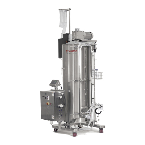
Chapter 1 S.U.F. overview 1.1 Introduction The Thermo Scientific Single-Use Fermentor (S.U.F.) has been designed to be a single-use alternative to conventional stirred tank aerobic fermentors currently utilized in microbial cell culture applications. Based on years of accepted stirred tank reactor (STR) design, the S.U.F. - Page 16 Chapter 1 S.U.F. overview Figure 1.1. 300 L S.U.F. with electrical control panel, condenser, cable management system, and bottle management system The stainless steel outer support container is engineered and fabricated to fully support each S.U.F. BioProcess Container (BPC) and allow easy access for operation. The outer support container is mounted to a portable cart base and includes the mixing drive, water jacket for heating and cooling, and optional controllers for mixing.
- Page 17 Chapter 1 S.U.F. overview The BPC includes the impeller assembly, sparger, vent filter inlet/outlet ports, probe integration ports, and filling, dispensing, and sampling ports. The materials are fully qualified for biological product contact per USP Class VI plastics. Each assembly is manufactured under cGMP and is supported by qualification and validation information.
-
Page 18: Hardware Characteristics
Chapter 1 S.U.F. overview 1.2 Hardware characteristics 1.2.1 System features The S.U.F. is designed for system mobility and easy integration while utilizing a straightforward operator interface. Hardware drawings and specification tables specific to volume can be found in Chapter 4 of this guide. -
Page 19: Temperature
Chapter 1 S.U.F. overview 1.2.6 Temperature The S.U.F. can be operated within the temperature range from 5°C to 55°C. The process temperature is measured by means of a supplied RTD (pt-100) that is inserted into the thermowell of the S.U.F. BPC. Water jacketed system temperature control is maintained through the TCU or a third-party controller. -
Page 20: End User And Third-Party Supplied Components
Chapter 1 S.U.F. overview 1.3 End user and third-party supplied components 1.3.1 pH and DO probes The following table shows the length and diameter requirements for traditional sensors (probes) that can be integrated into the S.U.F. These requirements are based on the necessary insertion depth of the probe when used with the probe ports. -
Page 21: Controllers
Chapter 1 S.U.F. overview 1.3.3 Controllers Thermo Scientific operates with an open architecture approach to the integration of controls. Our industry-leading S.U.F. can be integrated with most controllers on the market, allowing customers to choose the control system they want, or to reduce expense by integrating with a controller that is already onsite. -
Page 22: Bioprocess Container Characteristics
Chapter 1 S.U.F. overview 1.4 BPC characteristics 1.4.1 S.U.F. BPC features The microbial culture itself is contained inside the S.U.F. BPC (Figures 1.2 and 1.3). The chamber is manufactured from single-web, multi- layer film, which is a co-extruded structure specifically designed for biopharmaceutical process usage. -
Page 23: Draining And Harvest
Chapter 1 S.U.F. overview 1.4.4 Draining and harvest The S.U.F. is equipped with a bottom drain line that allows for liquid harvest, typically with a peristaltic pump. Connection of the bottom drain line can be accomplished by use of a tubing welder or the aseptic connection of quick connect or fitting that is provided. -
Page 24: Bpc Features
Chapter 1 S.U.F. overview 1.4.8 BPC features Figures 1.2 and 1.3 illustrate the components of standard 30 L and 300 L S.U.F. BPCs. See Table 1.2 on the following page for more information. Figure 1.2. 30 L S.U.F. BPC Figure 1.3. 300 L S.U.F. BPC Thermo Scientific HyPerforma Single-Use Fermentor User’s Guide... - Page 25 Chapter 1 S.U.F. overview Table 1.2. BPC information for Figures 1.2 and 1.3. Component Description 1. Exhaust vent filter Single-use capsule filter for exhaust gas exchange (two types available) 2. Condenser bag (optional) Optional single-use condenser bag Built-in single-use sensor may be used with a controller to automatically 3.
-
Page 26: Additional System Components
Chapter 1 S.U.F. overview 1.5 Additional system components 1.5.1 Probe integration The probe assembly is an innovative design to package user-supplied pH and DO probes for sterilization and to aseptically connect them to the S.U.F. BPC. The probe assembly (Figure 1.4) includes the following components: 1. - Page 27 Chapter 1 S.U.F. overview • Load cells—Load cell packages include three load cells, summing block, wiring, and an optional display screen with your choice of several data interfaces • Cable management system • Bottle management system • Feed bag management hook See Chapter 4 of this guide for accessory ordering information.
-
Page 28: Chapter 2 Installation And Setup
Chapter 2 Installation and setup Installation and setup Chapter contents Initial installation preparation Installation Thermo Scientific HyPerforma Single-Use Fermentor User’s Guide... -
Page 29: Initial Installation Preparation
Chapter 2 Installation and setup 2.1 Initial installation preparation The Single-Use Fermentor (S.U.F.) hardware will arive crated. For unpacking instructions and detailed contents of the crate, please refer to the S.U.F. Packing and Unpacking Guide. Be sure to follow the instructions provided and retain all packaging materials. -
Page 30: Outer Support Container Preparation
Chapter 2 Installation and setup 2.2.2 Outer support container preparation Each outer support container is shipped from the manufacturer and arrives with various safety mechanisms in place. Please follow the guidelines below to set up the S.U.F. upon arrival. WARNING: Any procedures that require the electrical control panel (E-Box) to be opened should be performed with the main electrical disconnect in the locked out position, and all power sources removed. -
Page 31: Load Cell Preparation
Chapter 2 Installation and setup 4. Fermentor units are shipped with the main electrical breaker in the off position. Turn the main breaker on. 5. Close the E-Box and lock the panel. 2.2.4 Load cell preparation 1. For S.U.F. units purchased with factory-installed load cells, the load cells are shipped in the locked position (threaded up) for equipment protection. -
Page 32: Installation
Chapter 2 Installation and setup 2. At this point, the S.U.F. hardware is ready to prepare for a cell culture run. CAUTION: Do not move unit, especially when filled, while load cells are unlocked, as this can damage the load cells. 3. - Page 33 Chapter 2 Installation and setup 5. Verify the location of the pH/DO controllers and assure cable/tubing lengths are satisfactory. WARNING: Electrical shock is possible. 6. Verify that the main power is off and the emergency stop is pulled out. Note: The emergency stop disconnects all power to the system. An alarm buzzer will sound when the emergency stop is activated.
-
Page 34: Exhaust Filter Bracket Setup
Chapter 2 Installation and setup 2.3.1 Exhaust filter bracket setup To install the exhaust filter bracket, clamp it onto the rim of the S.U.F. tank. Push the red handles down to lock it into place (Figure 2.5). The exhaust filter post will slide into the hole in the bracket. The center red handle locks the post in place. -
Page 35: Tcu/Chiller Connection To Condenser Unit
Chapter 2 Installation and setup 300 L condenser attached to rim mount Figure 2.7. Condenser installed on a 300 L system 2.3.3 TCU/chiller connection to condenser unit (optional) Use the following steps to connect a TCU or chiller to the S.U.F. condenser unit, if present. - Page 36 Chapter 2 Installation and setup 2. Connect the hose(s) from the port marked as “Process Inlet” on the TCU to the outlet port(s) on the condenser. On 300 L systems, the condenser inlet ports are the ones closest to the tank, on opposite condenser plates.
-
Page 37: Exhaust Filter Pinch Clamp Setup (When Present)
Chapter 2 Installation and setup Figure 2.10. Attaching line to a TCU unit Figure 2.11. Attaching a clamp to a line 2.3.4 Exhaust filter pinch clamp setup (when present) Some systems include an exhaust filter pinch clamp (Figure 2.12), which is used to temporarily keep exhaust from flowing through redundant exhaust filters. -
Page 38: Optional Cable Management System Setup
Chapter 2 Installation and setup Pinch clamp installed onto exhaust system post with C bracket Figure 2.13. Pinch clamp installed on a 300 L S.U.F. 2. Lift the center red handle of the exhaust bracket. Slide the exhaust filter holder post into the bracket and lock the center handle down. 3. -
Page 39: Air Line Preparation
Chapter 2 Installation and setup Use of the cable management system is covered in detail in the BPC loading instructions in Chapter 3 of this guide. 2.3.6 Air line preparation See Table 3.2 and Table 3.3 (later in this guide) for recommended air flow rates. -
Page 40: Operating Information
Chapter 3 Operating information Operating information Chapter contents General system operating information BPC and drive shaft loading instructions for 30 L units BPC and drive shaft loading instructions for 300 L units Exhaust system Probe assembly Microbial cell culture operating instructions BPC sampling Verification procedures Thermo Scientific... -
Page 41: General System Operating Information
Chapter 3 Operating information 3.1 General system operating information 3.1.1 BPC preparation and loading Each outer support container is designed for a specific S.U.F. BPC. Confirm that the correct volume BPC is being used for the corresponding volume outer support container. This section outlines the installation and setup of the different volume S.U.F. - Page 42 Chapter 3 Operating information Sampling The S.U.F. is equipped with a small volume sample port that is part of the BPC thermowell. This small diameter (1.59 x 4.76 mm [1/16 x 3/16 in.]) silicone dip tube of 152.4 mm (6 in.) length allows low void volume samples to be taken for cell viability and density, as well as analyte analysis.
- Page 43 Chapter 3 Operating information Extensive testing has not found an occurrence of overpressure sufficient to create a containment breach. Development testing of the BPC system has shown that in conditions of excessive pressure the polymer container will fail at the upper regions of the chamber where it is unsupported by the outer support container, minimizing the likelihood of the loss of bulk liquid.
-
Page 44: Hardware Operating Information
Chapter 3 Operating information 3.1.4 Hardware operating information Temperature Temperature setpoints can be adjusted via the temperature control unit (TCU). These setpoints should be between 5°C and 55°C. The process temperature is measured by means of a supplied resistance temperature detector (RTD) (pt-100) that is inserted into the thermowell of the S.U.F. - Page 45 Chapter 3 Operating information Protective earth grounding Protective earth grounding for the S.U.F. hardware system and the controller is provided through the ground terminal of the power plug. Source power to the controller must provide protective earth grounding to this terminal in order to minimize the hazard of a possible shock in the occurrence of a fault condition.
- Page 46 Chapter 3 Operating information Use the following steps to lock the load cells before transporting a S.U.F., and refer to Figures 2.3 and 2.4 in section 2.2.4 (earlier in this guide). 1. Hand-tighten the load cell lockout nut onto the load cell lockout post.
-
Page 47: Bpc And Drive Shaft Loading For 30 L Units
Chapter 3 Operating information 3.2 BPC and drive shaft loading for 30 L units 3.2.1 Initial installation steps for 30 L units Each outer support container is designed for a specific S.U.F. BPC. Confirm that the correct volume BPC is being used for the corresponding volume outer support container. - Page 48 Chapter 3 Operating information 2. Orient the BPC with the bearing port up and toward the motor drive, with the connector probe ports facing the bottom access cutout. 3. Remove the cap on the BPC bearing port, and place the bearing port into the bearing port receiver (Figure 3.3).
- Page 49 Chapter 3 Operating information 5. Route the sparge line and bottom drain line through the bottom access opening (Figure 3.5). Figure 3.5. Routing the sparge and bottom drain lines 6. Open the door of the condenser unit, if present, and feed the condenser portion of the bag through the condenser.
- Page 50 Chapter 3 Operating information 8. Straighten and smooth the condenser bag in the condenser unit, if present, and close and latch the door of the condenser (Figure 3.7). Ensure that the condenser BPC is not too tight or too loose in the condenser hardware unit.
- Page 51 Chapter 3 Operating information 10. If a cable management system is available, attach the lines to the appropriate inlet ports (Figures 3.9, 3.10, and 3.11). Figure 3.10. Incoming line connection Figure 3.9. Line setup on the cable management system Figure 3.11. Incoming line connection to a direct sparger filter 11.
- Page 52 Chapter 3 Operating information 13. Use the bottom cutouts located at the base of the support container as a reference to align the hanging tabs on the BPC. 14. Attach the two hanging tabs on the bottom of the BPC to the tab holders (pins) on the S.U.F.
- Page 53 Chapter 3 Operating information 16. To allow for drive shaft insertion, fill the BPC with air for approximately 10–20 minutes (times will vary based on flow rate, inlet pressure, and container volume). WARNING: To prevent damaging the BPC, the BPC must be partially inflated before you begin to insert the drive shaft.
- Page 54 Chapter 3 Operating information 4. Position the alignment cutout on the exhaust filter BPC, over the pin on the left side of the clamping surface for 30 L units (Figure 3.15). Note: On 300 L units, this pin is at the top of pinch clamps. Figure 3.15.
-
Page 55: Drive Shaft Insertion For 30 L Units
Chapter 3 Operating information Figure 3.18. Pushing the pinch clamp closed 8. When using the system, if the first set of filters become fouled, the pinch clamp can be manually opened to enable the backup filter. This should only be done when the pressure in the BPC is 0.034 (0.5 psi) or 0.041 bar (0.6 psi), and no foam is detected in the headspace. - Page 56 Chapter 3 Operating information 2. Unscrew the threaded cap covering the pass-through of the motor. 3. Use the following steps to insert the drive shaft through the pass- through of the motor (Figures 3.20 and 3.21). • Use two hands to load the drive shaft through the top of the motor assembly;...
- Page 57 Chapter 3 Operating information 4. Use the following steps to directly couple the drive shaft to the motor drive (Figures 3.22–3.24). • Place the threaded cap on the hollow pass-through and hand- tighten in a clockwise direction (Figure 3.22). • Tighten the cap by placing the spanner wrench on the hollow pass-through and tighten the cap using the supplied torque wrench (Figure 3.23).
-
Page 58: Final Installation Steps For 30 L Units
Chapter 3 Operating information 3.2.3 Final installation steps for 30 L units 1. Position and close a bar clamp on the bottom drain line as close as possible to the BPC port (Figure 3.25). Figure 3.25. Closing bar clamp on drain line 2. - Page 59 Chapter 3 Operating information 4. Optional: Connect the pressure sensor to the monitoring device. WARNING: Do not over-inflate the BPC, as it could rupture. An automatic high-pressure gas shutoff device is recommended. 5. Refer to section 3.5 for probe insertion instructions. 6.
-
Page 60: Bpc And Drive Shaft Loading For 300 L Units
Chapter 3 Operating information 3.3 BPC and drive shaft loading for 300 L units 3.3.1 Initial installation steps for 300 L units Before beginning to load the BPC, verify that the S.U.F. hardware is stationary with casters locked into place. BPC loading may require operators to step inside the fermentor, and the unit must be stationary for the safety of both the operator and the equipment. - Page 61 Chapter 3 Operating information Figure 3.31. BPC in protective polybags 4. Reach into the outer support container with the front face (bearing port side) of the BPC oriented towards the motor (Figure 3.32). Figure 3.32. Bearing port orientation Note: These steps may also be performed from the top of the unit. Be sure to use caution when using a ladder.
- Page 62 Chapter 3 Operating information Figure 3.33. Preparing to place bagged lineset over edge of container 6. From inside the tank or from an elevated position, slide the exhaust port into the exhaust port bracket at the top of the outer support container (Figure 3.34).
- Page 63 Chapter 3 Operating information Exhaust port latch (closed) Figure 3.35. Exhaust port sliding latch (removed from the tank) Slide latch to lock exhaust port in place Figure 3.36. Locking the exhaust port 7. Remove the cap from the bearing port in the BPC and load the bearing port into the receiver (Figure 3.37).
- Page 64 Chapter 3 Operating information 8. If the motor was unlocked to facilitate insertion of the bearing port, lock the motor back into position. WARNING: Failing to lock the motor into position may cause harm to personnel or damage the BPC. 9.
- Page 65 Chapter 3 Operating information Drain line cutout Sparge line cutouts Figure 3.41. Removing the guide plate Figure 3.42. Replacing the guide plate 11. Extend the tubing through the bottom of the outer support container. Ensure that the tubing isn’t pinched or kinked under the container (Figure 3.43).
- Page 66 Chapter 3 Operating information Optional: If you are using the optional exhaust filter pinch clamp to control airflow to redundant filters, follow the steps listed under the Use of Exhaust Filter Pinch Clamp (when present) section, which is located in the BPC loading for 30 L units section. The same pinch clamp is used for both S.U.F.
- Page 67 Chapter 3 Operating information 14. Remove the bubble wrap from the inlet filter and sparge line (Figure 3.45), connect to gas supply, and partially inflate the BPC. This will allow for proper insertion of the drive shaft and aid in aligning the BPC in the outer support container.
-
Page 68: Drive Shaft Insertion For 300 L Units
Chapter 3 Operating information 3.3.2 Drive shaft insertion for 300 L units The motor and mixing assembly in Figure 3.47 serves as a reference for drive shaft assembly and insertion. The drive shaft is constructed using three pieces, which must be assembled and inserted piece by piece. Operators should be elevated (i.e. - Page 69 Chapter 3 Operating information 1. Prepare the hollow pass-through by first removing the latch pin on the safety cover (Figure 3.48), opening the safety cover, and removing (by turning counter-clockwise) the threaded drive shaft cap of the mixing assembly (Figures 3.49 and 3.50). Figure 3.48.
- Page 70 Chapter 3 Operating information 3. First insert the lower section through the hollow pass-through of the motor drive. Slide the latch pin from the motor assembly into the shaft to prevent it from falling into the tube (Figure 3.51). Assemble the middle and lower sections of the drive shaft by joining the segments with a twisting motion, fastening the two sections together (Figure 3.52).
- Page 71 Chapter 3 Operating information 4. Load the partially assembled drive shaft through the hollow pass- through and hold it in position with the latch pin. Obtain the upper section of the drive shaft and assemble it to the middle segment in the manner described previously.
- Page 72 Chapter 3 Operating information Figure 3.56. Replacing the drive shaft cap 7. Tighten the cap by placing a spanner wrench counterclockwise on the hollow pass-through. Tighten using the supplied torque wrench (Figure 3.57). Note: The torque wrench is a standard 10 mm (3/8 in.) square drive, and it is calibrated at the factory at 16.9 Nm (150 in-lb.
-
Page 73: Final Installation Steps For 300 L Units
Chapter 3 Operating information 3.3.3 Final installation steps for 300 L units 1. Fully extend the ports through the front cutout of the outer support container, and attach the probe clips (Figure 3.58). Figure 3.58. Attaching a probe clip 2. Remove the polybag from the drain line set (Figure 3.59), position the line clamp as close as possible to the BPC port, and close the clamp (Figure 3.60). - Page 74 Chapter 3 Operating information 4. Use the following steps to insert the RTD or selected temperature sensor into the thermowell (Figure 3.61). • Place a small amount of glycerol (0.5 mL) in the well to aid in heat transfer. • Insert the sensor until the base of the RTD meets the mouth of the thermowell.
- Page 75 Chapter 3 Operating information 7. Attach the ground clip to the stainless steel insert in the RTD/ sampling port (Figure 3.63). RTD/sampling port BPC ground clip Figure 3.63. Foam sensor ground clip on the RTD 8. If your system includes a cable management system, refer to the instructions for setting up the cable management system in the BPC Loading for 30 L Units in section 3.2 of this guide.
-
Page 76: Exhaust System
Chapter 3 Operating information 3.4 Exhaust system 3.4.1 Exhaust system functional overview The condenser is intended to be used as an accessory to the S.U.F. in conjunction with vent filter heaters, which are necessary with or without the condenser. The condenser’s purpose is to prevent liquids and solids from condensing and collecting inside of the vent filters of the S.U.F. -
Page 77: When To Use The Condenser
Chapter 3 Operating information 3.4.2 When to use the condenser Large 254 mm (10 in.) hydrophobic polyethylene vent filters with a nominal 0.2 micron pore size increase the available surface area for off-gassing. In addition, the standard 30–300 L S.U.F. is designed for use with an optional condenser. -
Page 78: Condensers And Reserve Vent Filters
Chapter 3 Operating information 3.4.3 Condensers and reserve vent filters All systems, especially large systems, benefit from the use of a condenser. The condenser increases system reliability at high flow rates beyond 1 vvm (or 30 splm for 30 L vessels, and 300 slpm for 300 L vessels), and warrants strong consideration when performing batch runs beyond one day at 1 vvm (or three days at lower vvms). -
Page 79: Exhaust System Setup
Chapter 3 Operating information 9. Check the indicator or window on the front of the TCU to ensure that the reservoir is still at least at the minimum level. 10. The settings for the TCU and peristaltic pump are preset at the factory. - Page 80 Chapter 3 Operating information 5. Place the top(s) of the filter(s) into the filter bracket(s) (Figure 3.66). Adjust the height of the filter bracket, as needed. Make sure that the position of the filter is not pulling the BPC condenser too tight, pinching off the air flow.
- Page 81 Chapter 3 Operating information 7. Place the vent filter heater(s) around the filter(s), looping the top strap of the heater around the metal bar on the filter bracket, and using the snap to secure them in place (Figure 3.68, Figure 3.69). Figure 3.68.
- Page 82 Chapter 3 Operating information 9. Verify that both the pump and TCU or chiller are enabled and running at the proper settings. We recommend a pump setting of 12–30 rpm, and a TCU/chiller setting of 5°C. Condensate flow should be verified at the maximum gas flow settings. 10.
-
Page 83: Probe Assembly
Chapter 3 Operating information 3.5 Probe assembly 3.5.1 Preparation and sterilization ™ 1. Select the appropriate probe. Verify the presence of a Teflon support ring and O-ring on the probe, and visually inspect them for damage. 2. Perform any required probe maintenance, and calibrate the pH probe (see the probe calibration topic in this section of the user’s guide). -
Page 84: Making Cpc Aseptiquik Connections
Chapter 3 Operating information 8. Allow sufficient time for probe assemblies to cool completely before seeking to connect to the BPC for probe insertion. 9. When stored properly, the autoclaved probe assemblies can be stored dry for short periods of time (less than 24 hours) without loss of sensor longevity, performance, or sterility. - Page 85 Chapter 3 Operating information Figure 3.74. Pulling the tear strip Figure 3.75. Removing the plastic covering from the connector 2. Unsnap and flip open the protective cover pull tabs on both connectors (Figures 3.76 and 3.77). Figure 3.76. Opening the protective cover pull tab on the port Figure 3.77.
- Page 86 Chapter 3 Operating information 3. Align the two connectors and push them together. 4. Squeeze each side of the connectors until you hear a click (Figure 3.78). Figure 3.78. Squeezing connectors together 5. Grab the joined pull tabs and pull upward to remove the paper membranes from the connectors (Figure 3.79).
-
Page 87: Probe Insertion
Chapter 3 Operating information 3.5.3 Probe insertion Before beginning probe insertion, please become familiar with the CPC AseptiQuik connector procedure outlined in section 3.5.2. If you are using Kleenpak connectors instead, refer to section 3.5.5. 1. Attach probe clips onto the outer support container above the probe assembly (Figure 3.80). - Page 88 Chapter 3 Operating information 3. Insert the probe by collapsing the bellows (Figure 3.82). Note: If the BPC is already filled with liquid, the best practice is to squeeze the bellows to expel air prior to collapsing it. Then insert the probe fully, as described.
-
Page 89: Probe Calibration
Chapter 3 Operating information 3.5.4 Probe calibration Probe calibration is controller-specific. However, the following general rules apply: • pH probes must be calibrated prior to steam sterilization. The calibration of the probe can be standardized by comparison of an off-line sample after the pH probe has been connected to the S.U.F. •... - Page 90 Chapter 3 Operating information • Male and female connectors are supplied protected by an inner and outer bag. Ensure that the packaging is undamaged. • The assembly aid is provided non sterile and can be reused multiple times. It needs to be stored in clean and dry conditions between each use.
- Page 91 Chapter 3 Operating information Autoclave sterilization • Install the male or female connector to the equipment to be sterilized. If the connector is attached to a tank, the tank should be vented appropriately with a vent filter. • Ensure that the protective cap of the connector is firmly in place. Autoclave paper or other autoclavable and air/steam permeable material can be used to cover the cap loosely to ensure that the cap does not become dislodged during handling.
- Page 92 Chapter 3 Operating information Making the connection using the connector assembly aid See the next section of this guide for instruction about making the connection without using the connector assembly aid. FEMALE PART* Locking clips (on both sides) Protective caps MALE PART* Plunger Barrel...
- Page 93 Chapter 3 Operating information 2. Hold the barrel of the larger (male) connector above the base. • Align the smaller (female) connector with the larger (male) connector. • Flat sides should be aligned. • Both peel away strips need to remain folded (Figure 3.86). Rounded side Female Anti-actuation ring...
- Page 94 Chapter 3 Operating information Remove the anti-actuation ring from the male connector Figure 3.88. Removing anti-actuation ring Note: Connector should stay securely in the assembly aid when properly installed. Assembly aid (cross section view) Peel away strips Figure 3.89. Cross-section view of assembly aid 5.
- Page 95 Chapter 3 Operating information WARNING: Do not use if only one peel away strip is removed accidentally instead of two, this will affect the sterility of the pathway. 6. With the connector still secured in the assembly aid, push the thumb rest of the male connector down towards the base of the barrel (Figures 3.92 and 3.93).
- Page 96 Chapter 3 Operating information Making the connection without using the connector assembly aid 1. Lift and pull tab off protective caps to remove caps from connectors (Figure 3.95). Protective caps Figure 3.95. Removing caps from connectors 2. Hold the barrel of the larger (male) connector above the base. •...
- Page 97 Chapter 3 Operating information Locking clips (not visible) Locking clips Figure 3.97. Pressing connectors together 4. Support both the male and female connectors, and remove the anti-actuation ring from the male connector by pulling the tab towards the barbed end of the male connector (Figure 3.98). Remove the anti-actuation ring from the male connector Figure 3.98.
- Page 98 Chapter 3 Operating information Figure 3.99. Holding assembly aid Figure 3.100. Pulling peel away with thumb supporting connector strips WARNING: Do not use if only one peel away strip is removed accidentally instead of two, this will affect the sterility of the pathway. 6.
-
Page 99: Microbial Cell Culture Operating Instructions
Chapter 3 Operating information 7. Start the fluid transfer (Figure 3.103). Figure 3.103. Starting fluid transfer 3.6 Microbial cell culture operating instructions Before beginning your fermentation run, please refer to the checklist in Appendix D to ensure that all necessary steps have been completed. 3.6.1 Operating conditions for microbial cell culture applications Optimal operating parameters for microbial cell culture vary greatly... -
Page 100: Manual Operation Of Drilled Hole Spargers
Chapter 3 Operating information Table 3.2. S.U.F. range of operating parameters (based on the ZenPure filter option; using Meissner filters may lower operating parameters). 30 L 300 L 2–45°C ± 0.1 Temperature (°C) Operating volume (L) 6–30 60–300 Agitation rate (rpm) 55–600 35–375 Recommended maximum gas flow... -
Page 101: Checkpoints Prior To Media Fill
Chapter 3 Operating information For more information on the growth of specific cell lines in the S.U.F. system, please contact technical support (see Chapter 6). 3.6.3 Checkpoints prior to media fill Verify the following before proceeding to liquid fill. √ The BPC has been loaded into the outer support container following the instructions provided in section 3.2 or 3.3. -
Page 102: Agitation For Units With Electrical Control Boxes
Chapter 3 Operating information 6. Fill to the desired liquid volume—20–100% of the rated volume is recommended. 7. If employing a liquid batch-to-tank grounding cable with the stainless steel connector of the sample line, the sample line should be purged of air prior to probe calibration. 3.6.5 Agitation for units with E-Boxes 1. -
Page 103: Temperature Control
Chapter 3 Operating information Table 3.4. Recommended operation for selected liquid volumes (maximum rpm) Maximum rpm in Maximum rpm in Liquid volume 30 L unit 300 L unit 275 rpm 15 L 350 rpm 30 L 598 rpm 60 L 120 rpm 150 L 240 rpm... -
Page 104: Ph Probe Calibration
Chapter 3 Operating information 3. Temperature setpoints should be between 5°C and 55°C. These setpoints are controlled by the TCU. Refer to the TCU manufacturer’s guidelines for setup and operating instructions. 3.6.7 pH probe calibration In general, the pH probe calibration (post-autoclave) can be verified by pulling a sample and analyzing the pH on another calibrated pH meter. -
Page 105: In-Process Checkpoints
Chapter 3 Operating information Note: For shear sensitive cultures, cells can be introduced by manipulating the addition port to direct the inoculum down the interior wall of the BPC and into the bulk fluid, reducing the shear on the cells. Custom line sets can be supplied with dip tubes, which shorten the distance between the point of inoculum introduction and the bulk fluid level. -
Page 106: Shutdown And Post-Use Bpc Disposal
Chapter 3 Operating information 3.6.13 S.U.F. shutdown and post-use BPC disposal 1. Once a run is complete and the contents have been harvested (drained), turn off the motor controller power switch on the E-Box. Check to make sure the motor is off and the drive shaft is not rotating. -
Page 107: Preparation For The Next Run
Chapter 3 Operating information 3.6.14 Preparation for the next run Between runs, the S.U.F. hardware (outer support container, probe shelf, drive shaft and mixer drive, etc.) can be wiped down with a sanitary wipe. Store the drive shaft in the storage holder located near the top of the outer support container. -
Page 108: Bpc Sampling
Chapter 3 Operating information 3.7 BPC sampling During operation of the S.U.F., samples may need to be taken for monitoring of various parameters established by the user. The following describes two techniques for sampling: aseptic sampling via sterile syringe, and sampling with a sterile manifold. 3.7.1 Aseptic sampling Using a standard luer lock on a 60 mL syringe or sterile manifold: 1. -
Page 109: Sampling With Sterile Manifold
Chapter 3 Operating information 4. Apply a small amount of vacuum pressure by pulling out the syringe plunger slightly. 5. Open the pinch clamp and pull a sample (approximately 30–60 mL), using care not to allow any back flow. 6. Close the pinch clamp and remove the syringe (this will be a purge sample). - Page 110 Chapter 3 Operating information 4. Inspect the welds and open the flow path by pinching the welds. 5. Open two clamps at the inlet and the clamp at the purge container (100 mL container). 6. Purge the sample line by filling this container (recommended 30–60 mL).
-
Page 111: Verification Procedures
Chapter 3 Operating information 3.8 Verification procedures 3.8.1 Mixer speed verification To verify the mixer speed, use a calibrated tachometer. Expect accuracy of +/- 0.75% of full scale. Speed scaling can be modified if the calibration needs to be adjusted. Please refer to Appendix B for details. 3.8.2 Temperature controller verification To verify the temperature controller/RTD, use a S.U.F. -
Page 112: Specifications And Parts Information
Chapter 4 Specifications and parts information Specifications and parts information Chapter contents Hardware features and dimensions BPC specifications Made-to-order hardware Thermo Scientific HyPerforma Single-Use Fermentor User’s Guide... -
Page 113: Hardware Features And Dimensions
Chapter 4 Specifications and parts information 4.1 Hardware features and dimensions 4.1.1 30 L S.U.F. design features Figures 4.1 and 4.2 below illustrate the features of the 30 L Single-Use Fermentor (S.U.F.). Figure 4.1. Back view of 30 L S.U.F. Figure 4.2. -
Page 114: S.u.f. Design Features
Chapter 4 Specifications and parts information 4.1.2 300 L S.U.F. design features Figures 4.3 and 4.4 below illustrate the features of the 300 L S.U.F. Figure 4.3. Front/top view of 300 L S.U.F. Figure 4.4. Back view of 300 L S.U.F. 1. -
Page 115: S.u.f. Dimensions And Ordering Information
Chapter 4 Specifications and parts information 4.1.3 30 L S.U.F. dimensions Figure 4.5 below illustrates the dimensions of the 30 L S.U.F. Measurements are listed in (centimeters [inches]). Figure 4.5. 30 L S.U.F. dimensions All units come standard with four probe hangers, a drive shaft, and a resistance temperature device (RTD). -
Page 116: S.u.f. Dimensions And Ordering Information
Chapter 4 Specifications and parts information 4.1.4 300 L S.U.F. dimensions Figure 4.6 below illustrates the dimensions of the 300 L S.U.F. Measurements are listed in (centimeters [inches]). Figure 4.6. 300 L S.U.F. dimensions All units come standard with four probe hangers, a drive shaft, and an RTD. -
Page 117: And 300 L S.u.f. Hardware Specifications
Chapter 4 Specifications and parts information 4.2 30 L and 300 L S.U.F. hardware specifications Tables 4.1 and 4.2 provide specifications for the 30 L and 300 L S.U.F. systems. Table 4.1. 30 L and 300 L S.U.F. specifications. 30 L 300 L Rated liquid working volume 30 L... - Page 118 Chapter 4 Specifications and parts information Table 4.2. 30 L and 300 L S.U.F. specifications (continued). 30 L 300 L Agitation motor drive (type, voltage, phase) AC motor Induction, 208 VAC, 3 phase only Motor power rating (AC motor) 372.85 W (0.5 hp) 1,491.4 W (2 hp) Motor torque rating 4.6 Nm (40.7 in-lb.)
-
Page 119: Configurable Hardware Options
Chapter 4 Specifications and parts information 4.3 Configurable hardware options Made-to-order part numbers will be generated from customer-selected configurable items shown below. Table 4.3. Configurable hardware options. Category Options/capability Notes 120 VAC or 240 VAC with basic controls for motor E-Box Supports 50–60 Hz power rpm, pressure, and basic I/O... -
Page 120: Bpc Features And Specifications
Chapter 4 Specifications and parts information 4.4 BPC features and specifications 4.4.1 Standard 30 L S.U.F. BPC Figures 4.7, 4.8, and 4.9 below illustrate the standard 30 L S.U.F. BioProcess Container (BPC), which includes a condenser, foam sensor, single-use DO and pH sensors, and two vent filters. For more information, see Table 4.4. - Page 121 Chapter 4 Specifications and parts information Table 4.4. 30 L BPC specifications. Line Description Tubing set (ID x OD x length) End treatment 1 or 2 12.7 cm (5 in.) Meissner or 7.62 cm (3 Exhaust line 22.2 mm (7/8 in.) ID x 28.6 mm (1 1/8 in.) OD P.C. silicone x 10 cm (4 in.) in.) or 12.7 cm (5 in.) ZenPure exhaust filters, optional condenser bag...
-
Page 122: Standard 300 L S.u.f. Bpc
Chapter 4 Specifications and parts information 4.4.2 Standard 300 L S.U.F. BPC Figures 4.10 and 4.11 illustrate the standard 300 L S.U.F. BPC, which includes a condenser, foam sensor, single-use DO and pH sensors, and two vent filters. For more information, see Table 4.5. 3. - Page 123 Chapter 4 Specifications and parts information Table 4.5. 300 L BPC specifications. Line Description Tubing set (ID x OD x length) End treatment 9.5 mm (3/8 in.) ID x 15.9 mm (5/8 in.) OD C-Flex tubing x 213 cm (84 in.) splits to SterilEnz pouch with Media feed 6.4 mm (1/4 in.) ID x 12.7 mm (1/2 in.) OD C-Flex tubing x 30 cm (12 in.) reduced...
-
Page 124: Bpc Options And Packaging Information
Chapter 4 Specifications and parts information 4.5 BPC options and packaging information See Tables 4.6–4.8 for configurable and custom options for BPCs, as well as standard BPC packaging information. Table 4.6. Configurable BPC options. Category Options/capability Condenser BPCs are available with or without a condenser Film CX 5-14 or Aegis 5-14 Foam sensor... -
Page 125: Accessories And Options Specifications
Chapter 4 Specifications and parts information Table 4.8. BPC packaging for all sizes (as dry BPC systems). Supplied ‘flat-packed’ Outer packaging Two polyethylene outer layers Description Product code Label Lot number Expiry date on outer packaging and shipping container Sterilization Irradiation (25 to 40 kGy) inside outer packaging Shipping container Durable cardboard carton... - Page 126 Chapter 4 Specifications and parts information Figure 4.13. Mettler Toledo MTB load cell Figure 4.14. Load cell location Load cells are typically radial mounted in sets of three. The mounting location varies slightly for each size in order to allow easy access to the bottom drain or sparging mechanisms and tubing.
- Page 127 Chapter 4 Specifications and parts information Table 4.9. Load cell specifications. S.U.F. specification Weight module parameter 30 L 300 L Model number MTB-100 MTB-200 Rated capacity per load cell 100 kg (220 lb.) 200 kg (441 lb.) Load limit, safe See specification Maximum horizontal force 0.98 kN (220 lb.)
-
Page 128: Cable Management System
Chapter 4 Specifications and parts information Table 4.11. Ordering information for Mettler Toledo harsh mount load cell displays. Description Part number IND331 display, harsh mount style with analog interface (STD), 120 VAC US line cord/plug SV50177.306 IND331 display, harsh mount style with Allen-Bradley RIO interface, 120 VAC US line cord/plug SV50177.307 IND331 display, harsh mount style with Device Net interface, 120 VAC US line cord/plug SV50177.308... -
Page 129: Vent Filter Heaters
Chapter 4 Specifications and parts information Channel for sensor wires Figure 4.17. Adjustable arm and channel for sensor wires (back view) Table 4.12. Cable management system ordering information. Size Description Part number 30 L Cable management system SV51006.01 300 L Cable management system, left hand configuration SV51006.02 Cable management system, right hand 300 L... -
Page 130: Exhaust System
Chapter 4 Specifications and parts information Corrosion-resistant stainless steel snaps Contoured foam insulator for easy installation and removal prevents heat loss; molded 12.7 mm (1/2 in.) foam conforms to housing Thermocouple Preset temperature controller embedded in heater mat Figure 4.18. Vent filter heater Vent filter heaters are sold as a kit which includes vent filter heater, controller with a water-tight closure and an installation power cord. - Page 131 Chapter 4 Specifications and parts information The condenser protects against filter blockage by condensing out moisture prior to exhaust gases reaching the vent filters. BPCs are not intended to operate under pressure, and fouled (blocked) exhaust filters lead to bag pressurization. While vent filter heaters may prevent condensate build-up in many instances, with larger fermentors, this becomes less effective, whereas condensing out the moisture first is a more reliable method for preventing liquid from reaching the filters.
- Page 132 Chapter 4 Specifications and parts information Figure 4.20. Dimensions for 30 L S.U.F. units with condenser (measurements shown in centimeters [inches]) Figure 4.21. Dimensions for 300 L S.U.F. units with condenser (measurements shown in centimeters [inches]) Thermo Scientific HyPerforma Single-Use Fermentor User’s Guide...
-
Page 133: Miscellaneous Items
Chapter 4 Specifications and parts information Table 4.14. Condenser system ordering information. Description Part number Complete condenser system with 120 VAC for 30 L S.U.F. unit (TCU for SV51016.02 condenser is included) Complete condenser system with 240 VAC for 30 L S.U.F. unit (TCU for SV51016.03 condenser is included) Complete condenser system with 240 VAC for 300 L S.U.F unit (TCU for... - Page 134 Chapter 4 Specifications and parts information Exhaust filter pinch clamp The exhaust filter pinch clamp may be used to temporarily stop air flow to redundant exhaust filters (Figure 4.24). It is mounted to the exhaust filter pole and is closed with a pneumatic mechanism that is activated though the controller.
- Page 135 Chapter 4 Specifications and parts information Table 4.15. Miscellaneous items ordering information. Description Part number Autoclave tray SV50177.01 Probe assembly (non-sterile for use in autoclave) SH30720.01 Exhaust filter pinch clamp for 300 L system SV50177E.15 Exhaust filter pinch clamp for 30 L system SV50177E.16 Heavy duty tubing clamp (single) SV20664.01...
-
Page 136: Maintenance And Troubleshooting
Chapter 5 Maintenance and troubleshooting Maintenance and troubleshooting Chapter contents Maintenance Troubleshooting and frequently asked questions Thermo Scientific HyPerforma Single-Use Fermentor User’s Guide... -
Page 137: Maintenance
Chapter 5 Maintenance and troubleshooting 5.1 Maintenance 5.1.1 Routine maintenance Environmental conditions, operating parameters and the ability of the user to adhere to standard operating procedures as outlined in this user’s guide can have significant impact upon the useful life of the S.U.F. - Page 138 Chapter 5 Maintenance and troubleshooting Replace worn drive shaft head assembly when the hex diameter at its widest location measures equal to or less across the points (Figure 5.1). Diameters are measured at widest location across the points. • Lightly coat drive cap threads with food-grade anti-seize if the motor cap becomes difficult to turn.
-
Page 139: Troubleshooting And Frequently Asked Questions
Chapter 5 Maintenance and troubleshooting 5.2 Troubleshooting and frequently asked questions 5.2.1 Hardware operation issues Issue: The S.U.F. will not operate. Solution: Check the power supply. • Verify the main electrical plug connection at wall outlet, the position of main power disconnect, and the position of the emergency stop switch. - Page 140 Chapter 5 Maintenance and troubleshooting Issue: The mixer controller does not respond to user inputs. Solution: Allow the speed to stabilize before using the keypad interface. • Rapidly adjusting speed control in an excessive manner may require several seconds for speed stabilization. •...
-
Page 141: Cell Culture Operation Issues
Chapter 5 Maintenance and troubleshooting Issue: The load cells are reading incorrectly. Solution: Verify that the load cells and display are set up correctly. • Verify that the load cell lock outs have been released, and that the tri-clamps have been removed. •... - Page 142 Chapter 5 Maintenance and troubleshooting Issue: DO readings are erratic or unstable. Solution: Adjust the controller to suit the volume of the S.U.F. system. • Many different parameters can effect the ability of a fermentor controller to effectively maintain a target setpoint during process control.
- Page 143 Chapter 5 Maintenance and troubleshooting Issue: We are having difficulty controlling the volume and feed rate or supplement during a fermentor run. Solution: Use load cells or a scale to control volumes based upon weight. The S.U.F. is not equipped with level sensors, other than the maximum foam level sensor that is available as an option and measures foam in the head space of the BPC.
-
Page 144: Probe And Connector Issues
Chapter 5 Maintenance and troubleshooting 5.2.3 Probe and connector issues Issue: The pH and DO probes were not introduced prior to media fill. Can a sterile connection still be made under these conditions? Solution: If you are using standard probes, as long as the clamps were closed on the aseptic connector probe ports before liquid fill, you can make a sterile connection after the media fill. -
Page 145: Bpc And Sparging Issues
Chapter 5 Maintenance and troubleshooting 5.2.4 BPC and sparging issues Issue: The S.U.F. BPC seems overly tight. Solution: Verify container is venting and inspect for cause of overpressure. • Reduce inlet gas flow rate of the sparger. • Inspect exhaust filter and/or condenser for restriction or blockage. •... -
Page 146: General Ordering Information
Chapter 6 General ordering information General ordering information Chapter contents Ordering instructions Ordering/support contact information Technical support Thermo Scientific HyPerforma Single-Use Fermentor User’s Guide... -
Page 147: Ordering Instructions
Chapter 6 General ordering information 6.1 Ordering instructions BPCs and hardware components for the Single-Use Fermentor (S.U.F.) can be ordered directly from Thermo Fisher Scientific. These items include all components that have part numbers beginning with the following characters: • •... -
Page 148: Technical Support
Chapter 6 General ordering information 6.3 Technical support Technical support for the S.U.F. is available in a variety of formats. Some or all of the following may be appropriate, depending on individual experience and circumstances. Technical service hotline and email Contact your Thermo Scientific sales representative for general product pricing, availability, delivery, order information, and product complaints. -
Page 149: Appendix A-Installation Of Female Electrical Receptacle For
Appendix A Electrical receptacle installation Appendix A—Installation of female electrical receptacle for units with AC motors and electrical control panels 1. In order to complete the installation for units with AC motors, the facility must be equipped with an electrical housing of sufficient size. - Page 150 Appendix A Electrical receptacle installation 4. Check the condition of the three exposed wire leads, and strip them back to expose a new wire, if needed. 5. Connect the wire leads on the receptacle (shown in Figure A.2 below) using the screw terminals, paying strict attention to obtain the correct wiring position as it is labeled on the receptacle.
- Page 151 Appendix A Electrical receptacle installation 3-4X #10X1 in. screws to mount plug to adapter plate. Note: The plug will be offset to the left or right if mounting to a two-gang box with screws in opposite corners. If this is the case, then one of the holes in the plug will line up with the screw will need to be used in that hole.
-
Page 152: Appendix B-Mettler Toledo Ind331 Display Load Cell Calibration Instructions
Appendix B Mettler Toledo load cell calibration Appendix B—Mettler Toledo IND331 display load cell calibration instructions Please refer to the instructions and reference material found in the Mettler Toledo IND Terminal Technical Manual for specific procedures and troubleshooting methods. Verify the following before beginning load cell calibration: •... - Page 153 Appendix B Mettler Toledo load cell calibration For further information, refer to the Mettler Toledo IND331 manual at: http://mt.com Thermo Scientific HyPerforma Single-Use Fermentor User’s Guide...
-
Page 154: Appendix C-Pre-Fermentation Run Checklist
Appendix C Pre-fermentation run checklist Appendix C—Pre-fermentation run checklist Appendix C—Pre-fermentation run checklist Verify that the following steps are completed before beginning your cell Verify that the following steps are completed before beginning your cell culture run. culture run. Loading the BPC Loading the BPC √... - Page 155 Find out more at thermofisher.com/suf For Research Use or Further Manufacturing Only. Not for diagnostic use or direct administration into humans or animals. © 2018 Thermo Fisher Scientific Inc. All rights reserved. All trademarks are the property of Thermo Fisher Scientific and its subsidiaries unless otherwise specified.
Need help?
Do you have a question about the HyPerforma S.U.F. and is the answer not in the manual?
Questions and answers