
Related Manuals for ThermoFisher Scientific thermo scientific imPULSE S.U.M.


Summary of Contents for ThermoFisher Scientific thermo scientific imPULSE S.U.M.
- Page 1 imPULSE S.U.M. with Touchscreen Console User’s Guide DOC0099 • Revision A October 2020...
-
Page 2: Table Of Contents
Contents Warnings, safety, and warranty information How to use this guide Chapter 1 Introduction to the imPULSE S.U.M. with Touchscreen Console 1.1 Overview 1.2 Motor drive assembly 1.3 Pressure control device 1.4 Load cells 1.5 Powder port 1.6 BPC hoist system 1.7 imPULSE BPCs 1.8 Touchscreen Console characteristics 1.8.1 Touchscreen Console hardware components... - Page 3 Contents 3.4 Configuring modules 3.4.1 Alarms and interlocks 3.4.2 Configuring the Agitation module 3.4.3 Configuring the Mass module 3.4.4 Configuring the Timer module 3.4.5 Configuring the PCD module 3.4.6 Configuring the BPC Pressure module 3.4.7 Configuring the Pumps module 3.4.8 Configuring the Fill module 3.4.9 Configuring the Harvest module 3.4.10 Configuring the Temperature module 3.4.11 Configuring the pH module...
- Page 4 Contents 5.2.2 Loading the BPC 5.3 Probe preparation and insertion 5.3.1 Making CPC AseptiQuik connections 5.3.2 Making CPC AseptiQuik connections 5.3.3 Probe insertion 5.3.4 Inserting temperature sensors Chapter 6 Operating information 6.1 General hardware operating information 6.1.1 Heating performance 6.1.2 Protective earth grounding 6.1.3 Circuit protection 6.1.4 Scales and weighing systems 6.1.5 Using the E-Stop...
- Page 5 Contents 7.2 Touchscreen Console software maintenance 7.3 Preventive maintenance guidelines 7.4 imPULSE S.U.M. troubleshooting 7.5 Touchscreen Console troubleshooting Chapter 8 Specifications and parts information 8.1 Hardware features 8.2 Hardware specifications 8.3 Touchscreen Console specifications 8.4 BPC specifications 8.5 Parts and accessories ordering information 8.6 Configurable options Chapter 9 General ordering information...
-
Page 6: Warnings, Safety, And Warranty Information
Warnings, safety, and warranty information Warnings, safety, and warranty information ™ Congratulations! You have purchased high-quality Thermo Scientific equipment. We have included safety information in this guide, based on our knowledge and experience. It is important, however, for you to work with your safety management personnel to ensure that this equipment is integrated into your safety practices. - Page 7 Warnings, safety, and warranty information WARNING: Static electricity may build up in BPCs. • BioProcess Containers (BPCs) may act as insulators for electrostatic charge. If electrostatic charge is transferred to a BPC, the charge may be stored in the BPC and/or the product inside. This phenomena varies by product and use;...
- Page 8 Warnings, safety, and warranty information WARNING: Use caution with hazardous chemicals or materials. Personnel servicing equipment need to know the hazards of any chemicals or materials that may be present on or in the equipment. Use general hazard communication techniques such as a Safety Data Sheet (SDS), labels, and pictograms to communicate any hazards.
- Page 9 Warnings, safety, and warranty information Protective earth grounding Protective earth grounding must be verified prior to plugging the S.U.M. into any electrical outlet. Ensure the receptacle is properly earth grounded. Environmental conditions • Operating: 17 to 27°C; 20 to 80% relative humidity, non-condensing •...
- Page 10 Warnings, safety, and warranty information Warranty information Any warranties, if applicable, covering this equipment exclude: (a) normal wear and tear; (b) accident, disaster or event of force majeure; (c) your misuse, fault or negligence; (d) use of the equipment in a manner for which it was not designed;...
- Page 11 Warnings, safety, and warranty information Use restrictions You must use this equipment in accordance with our documentation and if applicable, with our other associated instructions, including without limitation, a “research use only” product label or “limited use” label license. This equipment is intended for research use or further manufacturing in bioprocessing applications and not for diagnostic use or direct administration into humans or animals, we do not submit the equipment for regulatory review by any governmental body or...
-
Page 12: How To Use This Guide
How to use this guide How to use this guide Scope of this publication This document covers information about installation, operation, specifications, and maintenance of Thermo Scientific ™ imPULSE ™ Single-Use Mixers (S.U.M.s) with Touchscreen Console. Document change information A summary of the changes that have been made to this document are listed below. - Page 13 How to use this guide Abbreviations/acronyms See the following list for definitions of abbreviations and acronyms used in this publication. BioProcess Container E-Box Electrical control panel E-Stop Emergency stop button GFCI Ground fault circuit interrupter Human-machine interface Pressure control device Resistance temperature detector S.U.M.
-
Page 14: Introduction To The Impulse S.u.m. With Touchscreen Console
Chapter 1 Introduction to the imPULSE S.U.M. with Touchscreen Console Introduction to the imPULSE S.U.M. with Touchscreen Console Chapter contents Overview Motor drive assembly Pressure control device Load cells Powder port BPC hoist system imPULSE BPCs Touchscreen Console characteristics Thermo Scientific imPULSE S.U.M. -
Page 15: Overview
Chapter 1 Introduction to the imPULSE S.U.M. with Touchscreen Console 1.1 Overview The imPULSE Single-Use Mixer (S.U.M.) with Touchscreen Console is designed for consistent mixing and scale-up, from 30 L up to 5,000 L. Its innovative disc technology and flexible design produce superior mixing, while configurable high-end controls and monitors fit user-specific process requirements. -
Page 16: Motor Drive Assembly
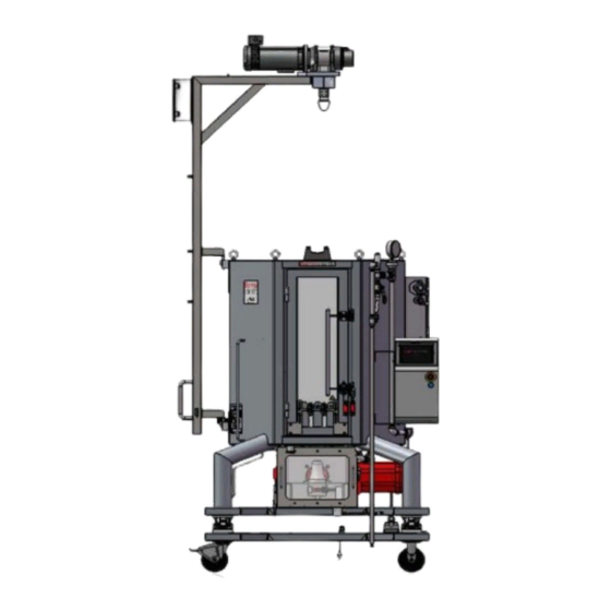
Chapter 1 Introduction to the imPULSE S.U.M. with Touchscreen Console BPC hoist Fixed powder port or (optional) Adjustable powder port (optional; not shown) Jacket pressure lines PCD Inflate/vent system (optional) Door for BPC loading AC motor module Touchscreen Console Probe insertion cutout Motor drive assembly Load cells... -
Page 17: Load Cells
Chapter 1 Introduction to the imPULSE S.U.M. with Touchscreen Console 1.4 Load cells Load cells or weight scales track operating volume and weight measurements, allowing you control over the liquid volume to rated working volume during the process run. A load cell kit is available for all S.U.M. units, and can be installed at the factory. -
Page 18: Touchscreen Console Characteristics
Chapter 1 Introduction to the imPULSE S.U.M. with Touchscreen Console Standard tube sets for liquid addition, recirculation, inflation, and vent control are also available for imPULSE BPCs. These tube sets can be customized to best suit your individual processes. Consult your Thermo Scientific sales representative for more information. -
Page 19: Touchscreen Console Features
Chapter 1 Introduction to the imPULSE S.U.M. with Touchscreen Console USB port Speaker Motor Control port (AC motor module Touchscreen COM) Pump/auxiliary Digital output ports (4) communication ports (6) Various communication ports (24) Emergency stop (E-Stop) button Main breaker switch Auxiliary breaker Reset switch... -
Page 20: Hardware Installation
Chapter 2 Hardware installation Hardware installation Chapter contents Site preparation Installation instructions Thermo Scientific imPULSE S.U.M. with Touchscreen Console User’s Guide... -
Page 21: Site Preparation
Chapter 2 Hardware installation 2.1 Site preparation 2.1.1 Electrical connections The power cable for the Touchscreen Console can be ordered with a country-specific plug to connect to facility power. For some countries, including the United States, the plug is amperage-specific. Verify that your facility power matches the power requirements of the Touchscreen Console power cable before use. -
Page 22: Installation Instructions
Chapter 2 Hardware installation Figure 2.1. Communication cable connection tool. 2.2 Installation instructions Before installing your imPULSE S.U.M., ensure that no damage has occurred during shipping. If your system has been damaged, contact your sales representative immediately. Follow the steps outlined in the imPULSE Single-Use Mixer Unpacking Guide (DOC0074) to unpack and move the vessel to the desired location in the facility. - Page 23 Chapter 2 Hardware installation 1. Use an adjustable wrench (not provided) to loosen the bolt (Figure 2.2). Bolt Figure 2.2. Drawing of load cells for stationary units. 2. Once the bolt is loosened enough, remove the centering spacers (Figure 2.3). The bolt should remain loosened until the vessel needs to be moved again.
- Page 24 Chapter 2 Hardware installation Figure 2.4. Inserting small screw jack over the top of the bolt. 4. After inserting the screw jack, use an adjustable wrench to raise the screw jack by turning clockwise (Figure 2.5). Figure 2.5. Using adjustable wrench to raise jack.
- Page 25 Chapter 2 Hardware installation If the imPULSE S.U.M. needs to be moved, the load cells must be locked again before transport. To lock load cells, use the following steps. 1. Reinsert the screw jack and use an adjustable wrench to raise it by turning clockwise.
-
Page 26: Initial Setup Steps
Chapter 2 Hardware installation 2.2.2 Initial setup steps 1. Verify that the electrical supply in the facility is sufficient to support the power requirements of the imPULSE S.U.M. and ancillary components, such as controllers or pumps. Connect the electrical power cord to the facility electrical power supply. 2. -
Page 27: Setting Up The Impulse S.u.m. With Touchscreen Console Hardware
Chapter 2 Hardware installation 5. All connections from the facility to the imPULSE S.U.M. (such as electrical power, glycol, water, air, and process gas) should be made with flexible connections to ensure accurate readings from the load cells. 2.2.3 Setting up the imPULSE S.U.M. with Touchscreen Console hardware Figure 2.12 on the next page illustrates the back panel of the Touchscreen Console. - Page 28 Chapter 2 Hardware installation Motor Controller (AC motor module COM) Speaker USB port Legacy port AC output ports (4) Pinch clamps Figure 2.12. Ports and connections on the back of the Touchscreen Console. Thermo Scientific imPULSE S.U.M. with Touchscreen Console User’s Guide...
- Page 29 Chapter 2 Hardware installation Before making connections 1. Verify that the main breaker and main power switch are in the “off” position. The selection switch should be pointing to the small circle to the left (Figure 2.13). 2. Verify that the emergency stop, referred to as the “E-Stop,” is disengaged (pulled out) by turning the knob clockwise (Figure 2.14).
- Page 30 Chapter 2 Hardware installation Connect the pumps 1. Plug the communication cables from the pump(s) into the pump/aux out ports on the back of the Touchscreen Console, and use the supplied tool to tighten (Figure 2.16). Figure 2.16. Connecting pumps to the Touchscreen Console.
- Page 31 Chapter 2 Hardware installation Connect the PCD inflate/deflate system (If applicable) 1. If your setup does not include a PCD, skip to the next section. For any system larger than 100 L, mount the PCD box to the vessel by hooking the mounting bracket over the top of the vessel and tightening the nuts.
- Page 32 Chapter 2 Hardware installation 4. Attach facility air to the air inlet port on the bottom left side of the PCD system. Note: Do not exceed 5.5 bar (80 psi). Connect facility air to the Touchscreen Console 1. If you are not using a PCD or are using pinch valves, connect facility air to the S.U.M.
- Page 33 Chapter 2 Hardware installation 2. Ensure the safety sensor cables are firmly connected to the AC motor module (Figure 2.26). Two interlocks are located on each side of the motor drive box (Figure 2.27), and one is located on the vessel door.
- Page 34 Chapter 2 Hardware installation • 2,000 and 5,000 L units do not require a summing box for load cells. When making connections, each of the three load cells can be plugged directly into the Touchscreen Console. 2. Use the auxiliary power ports on the back of the Touchscreen Console as needed.
-
Page 35: Touchscreen Console Setup
Chapter 3 Touchscreen Console setup Touchscreen Console setup Chapter contents Configuring the Touchscreen Console Home screen Module overview Required external components for modules Configuring modules Thermo Scientific imPULSE S.U.M. with Touchscreen Console User’s Guide... -
Page 36: Configuring The Touchscreen Console Home Screen
Chapter 3 Touchscreen Console setup 3.1 Configuring the Touchscreen Console Home screen 3.1.1 Introduction to the Touchscreen Console Figure 3.1 shows an example of the Touchscreen Console Home screen. See Table 3.1 for more information about the items that have been numbered on the screen. -
Page 37: Adding Modules To The Home Screen
Chapter 3 Touchscreen Console setup 3.1.2 Adding modules to the Home screen The Touchscreen Console uses “modules” to identify the functions users are able to access. Section 3.2.3 provides overview information about each module. Follow the steps below to add the modules you would like to use to the Home screen. - Page 38 Chapter 3 Touchscreen Console setup 3. The Select Auxiliary Outputs or Pumps screen appears (Figure 3.4). Touch the pumps and/or auxiliary outputs you would like to use to add them to your Home screen. You can select a combination of four pumps and/or auxiliary outputs. To deselect a pump or auxiliary output, touch the button again.
- Page 39 Chapter 3 Touchscreen Console setup 5. The Workspace Confirmation screen appears and displays the selected pumps/auxiliary outputs and modules (Figure 3.6). Click Confirm to add them to your Home screen. Figure 3.6. Workspace Confirmation screen. 6. The configured Home screen appears with your selected modules (Figure 3.7).
-
Page 40: Creating And Using An Administrator Profile
Chapter 3 Touchscreen Console setup 7. Ensure that the date and time displayed in the bottom right corner of the idle screen are correct. If either value is incorrect, touch the Settings icon in the top right corner and touch Instrument Settings to adjust the values. - Page 41 Chapter 3 Touchscreen Console setup Use the following steps to set up an Administrator profile. 1. Open System Settings by touching the Settings icon in the top right corner of the Home screen. Touch Administrator. 2. On the screen that appears, enter a PIN that will be required in order to log in as an Administrator.
-
Page 42: Module Overview
Chapter 3 Touchscreen Console setup 3.2 Module overview Each of the Touchscreen Console modules listed below provide the ability to monitor and control various functions. Some modules either require or can be optionally used with ancillary components, such as sensors or pumps. Many modules are also optionally dependent on ancillary components or other modules. - Page 43 Chapter 3 Touchscreen Console setup is optionally dependent on the TCU, as the TCU can be put on standby if the temperature reads higher or lower than specified setpoints. • pH—This module requires one or two pH sensors and can be used to monitor and adjust pH levels during the mixing process.
-
Page 44: Required External Components For Modules
Chapter 3 Touchscreen Console setup filter). The Liquid Pressure module is used to monitor the liquid pressure level during harvest to ensure that the filter is not clogged. The use of pumps and/or a Harvest pinch valve is optional with this module: the pinch valve will close and the pump will stop if the liquid pressure reads above a specified setpoint. -
Page 45: Configuring Modules
Chapter 3 Touchscreen Console setup 3.4 Configuring modules Each module configuration will have required and/or optional fields (e.g. setpoint and alarms, respectively) for customization. The following sections provide information about setting up alarms and interlocks, as well as individual modules. When the Touchscreen Console is first set up, each module has a Configuration button which provides access to configuration settings. -
Page 46: Configuring The Agitation Module
Chapter 3 Touchscreen Console setup – If Pause is selected as the Action taken, a Hysteresis equation must be set to specify conditions when operations will continue. – If Stop is selected as the Action taken, operations must be resumed manually. See the instructions for configuring modules in the following sections for more information. - Page 47 Chapter 3 Touchscreen Console setup Figure 3.11. Agitation Module Configuration screen. Required fields Setpoint limits Enter the minimum and maximum speeds (in Hz) that you would like to use during the mixing process (Minimum and maximum specifications are shown in Tables 8.1–8.8). 1.
- Page 48 Chapter 3 Touchscreen Console setup 3. After entering the setpoint limits, touch Done. 4. A confirmation screen will appear. Touch Done to return to the Configuration screen—the values in the Set point limits field will reflect your changes. Optional fields High and Low alarms Choose to enable or disable High and/or Low alarms.
- Page 49 Chapter 3 Touchscreen Console setup High High and Low Low alarms Choose to enable or disable High High and/or Low Low alarms. These alarms provide a visual and audible alert, and will pause or stop the TCU based on the set Interlock equations. 1.
-
Page 50: Configuring The Mass Module
Chapter 3 Touchscreen Console setup 6. After a moment, a confirmation screen will appear. Touch Done to return to the Configuration screen—the values in the High High and Low Low field will reflect your changes. Calibration Set up one-point agitation calibration to determine the accuracy of agitation readings. - Page 51 Chapter 3 Touchscreen Console setup Required fields There are no required fields for the Mass module. Optional fields High and Low alarms Choose to enable or disable High and/or Low alarms. These alarms provide a visual alert on the display when conditions are outside of specified operating parameters.
- Page 52 Chapter 3 Touchscreen Console setup High High and Low Low alarms Choose to enable or disable High High and/or Low Low alarms. These alarms provide a visual and audible alert, and will pause or stop specified pumps, pinch clamps, and/or agitation based on the set Interlock equations (See the section on Alarm Designation below).
- Page 53 Chapter 3 Touchscreen Console setup 6. Once you finish setting the High High and Low Low alarms touch Done. 7. After a moment, a confirmation screen will appear. Touch Done to return to the Configuration screen—the values in the High High and Low Low field will reflect your changes.
- Page 54 Chapter 3 Touchscreen Console setup Figure 3.19. Mass Alarm Designation (Pumps) screen. 3. On the screen that appears, move the corresponding slider to the Enable position for the High High and/or Low Low alarms to turn on the alarm(s) for agitation, or the selected pump or pinch valve (Figure 3.20).
-
Page 55: Configuring The Timer Module
Chapter 3 Touchscreen Console setup Calibration Set up one-point mass calibration to determine the accuracy of load cell mass readings. 1. If you would like to set up a mass calibration, touch the Calibration field. 2. Follow the calibration instructions in Chapter 4—Calibration procedures. - Page 56 Chapter 3 Touchscreen Console setup Figure 3.21. PCD Module Configuration screen. Required fields Units Set the units you would like displayed on the PCD module—mbar or psi. By default, the units are set to PSI. 1. To change the units, touch the Units field. 2.
- Page 57 Chapter 3 Touchscreen Console setup Figure 3.22. BPC Pressure High and Low Alarms screen. 2. To set either alarm, move the corresponding slider to the On position. 3. Touch the High or Low alarm field and enter the value (in PSI) in the that will trigger the High or Low alarm.
- Page 58 Chapter 3 Touchscreen Console setup Figure 3.23. BPC Pressure High High and Low Low Alarms screen. 3. Touch the Interlock field of an enabled alarm to enter the Interlock equation screen. 4. Fill out the Interlock equation by entering the Control setpoint (in either PSI or mbar) and selecting the Action taken (either Pause or Stop).
- Page 59 Chapter 3 Touchscreen Console setup Note: Enabling a pump allows it to adjust the air pressure after the alarm has been triggered. 2. On the screen that appears (Figure 3.24), you will see the interlock and hysteresis parameters that you entered for the High High and/or Low Low alarm(s).
-
Page 60: Configuring The Bpc Pressure Module
Chapter 3 Touchscreen Console setup 3.4.6 Configuring the BPC Pressure module The BPC module should only be used on systems where a PCD is not present. To begin, locate the BPC Pressure module on the Touchscreen Console Home screen, and touch Configure. The BPC Module Configuration screen will appear (Figure 3.25). - Page 61 Chapter 3 Touchscreen Console setup Optional fields High and Low alarms Choose to enable or disable High and/or Low alarms. These alarms provide a visual alert on the display when conditions are outside of specified operating parameters. 1. If you would like to set High/Low alarms for air pressure, touch the High and Low alarms field.
- Page 62 Chapter 3 Touchscreen Console setup 1. If you would like to set High High/Low Low alarms for air pressure, touch the High High and Low Low alarms field. 2. On the screen that appears, there are separate sections for both High High and Low Low alarms, each with respective Interlock and Hysteresis fields (Figure 3.27).
- Page 63 Chapter 3 Touchscreen Console setup Alarm designation (pumps) Use this field to specify which pump(s) are affected by the High High and/or Low Low alarms. 1. If you would like to designate alarms for pumps that have been set up, touch the Alarm designation (pumps) field on the BPC Module Configuration screen.
-
Page 64: Configuring The Pumps Module
Chapter 3 Touchscreen Console setup Calibration Set up a new BPC Pressure calibration using one-point offset. 1. If you would like to set up a BPC Pressure calibration, touch the Calibration field. 2. Follow the calibration instructions that are detailed in Chapter 4—Calibration Procedures. - Page 65 Chapter 3 Touchscreen Console setup 2. On the screen that appears (Figure 3.30), you will be prompted to enter the RPM values you would like the Touchscreen Console to display after converting from the output signal (in mA). Touch a field to change the value and touch Enter to confirm.
- Page 66 Chapter 3 Touchscreen Console setup Figure 3.31. Pump RPM Limits screen. 3. Touch Done. 4. The system will confirm the settings. Touch Done again to return to the Pump Module Configuration screen. Optional fields Pump name Each pump module (up to four total) can be given a distinct name to specify the purpose of the pumps.
-
Page 67: Configuring The Fill Module
Chapter 3 Touchscreen Console setup Figure 3.32. Renaming the Pump 1 module. Figure 3.33. Renamed Pump 1 module. 3. When you are finished, touch Enter. The Pump Module Configuration screen will reappear with the name you entered next to the Pump Name field with the added prefix (i.e. P1: Acid). Calibration Set up a new pump calibration using four-point calibration, and either mass or volume units. - Page 68 Chapter 3 Touchscreen Console setup Figure 3.34. Fill Module Configuration screen. Required fields Fill Pinch valve This field displays whether or not a pinch valve is detected and requires no setup. Units and liquid density Select the units you would like to use: either liters (L) or kilograms (kg). 1.
- Page 69 Chapter 3 Touchscreen Console setup 3. Touch Done when you are finished. The Fill Module Configuration screen will reappear with your changes reflected in the Units and Liquid Density field. Fill pump selection Select a pump to assign to the Fill module. 1.
- Page 70 Chapter 3 Touchscreen Console setup 2. Touch the drop down for either Start or Stop and select the condition that will either start or stop the pump (Figure 3.37). Refer to Table 3.3 for Start and Stop condition options. Figure 3.37. Fill Start and Stop condition screen. Table 3.3.
-
Page 71: Configuring The Harvest Module
Chapter 3 Touchscreen Console setup Figure 3.38. Fill Control screen. 4. Enter your desired values for the following fields: • Fluid target: The total amount of liquid you would like to pump into the BPC. Note: This is the only option available if there is not at least one pump set up. - Page 72 Chapter 3 Touchscreen Console setup Figure 3.39. Harvest Module Configuration screen. Required fields Harvest Pinch valve This field displays whether or not a pinch valve is detected and requires no setup. Units and liquid density Select the units you would like to use: either liters (L) or kilograms (kg). 1.
- Page 73 Chapter 3 Touchscreen Console setup 1. Touch Done when you are finished. The Harvest Module Configuration screen will reappear with your changes reflected in the Units and Liquid Density field. Harvest pump selection Select a pump to assign to the Harvest module. 1.
- Page 74 Chapter 3 Touchscreen Console setup 2. Touch the drop down for either Start or Stop and select the condition that will either start or stop the pump (Figure 3.42). Refer to Table 3.4 for Start and Stop condition options. Figure 3.42. Harvest Start and Stop condition screen. Table 3.4.
-
Page 75: Configuring The Temperature Module
Chapter 3 Touchscreen Console setup Figure 3.43. Pump selection on the Harvest Module Configuration screen. 4. Enter your desired values for the following fields: • Fluid target: The total amount of liquid you would like to pump out of the BPC. Note: This is the only option available if there is not at least one pump set up. - Page 76 Chapter 3 Touchscreen Console setup Figure 3.44. Temperature Module Configuration screen. Required fields Active temperature sensor Select the temperature sensor you would like to make active. 1. Touch the Active temperature sensors field. 2. On the screen that appears, select the temperature sensor you would like to make available for use.
- Page 77 Chapter 3 Touchscreen Console setup 4. A confirmation screen will appear. Touch Done to return to the Configuration screen—the values in the Set point limits field will reflect your changes. Optional fields High and Low alarms Choose to enable or disable High and/or Low alarms. These alarms provide a visual alert on the display when conditions are outside of specified operating parameters.
- Page 78 Chapter 3 Touchscreen Console setup High High and Low Low alarms Choose to enable or disable High High and/or Low Low alarms. These alarms provide a visual and audible alert, and will pause or stop the specified pumps based on the set Interlock equations. 1.
- Page 79 Chapter 3 Touchscreen Console setup Calibration Calibration for the temperature sensors can be found in the Temperature Module settings screen. Set calibration using one-, two-, or three-point offset. 1. Touch the top of the Temperature Module to open the Temperature Settings screen.
- Page 80 Chapter 3 Touchscreen Console setup SETTINGS MENU MENU REQUIRED PARAMETE INPUT PAR A RS485 Figure 3.49. Setup parameters for Lauda Integral T series TCU. QUICK START/ CALIBRATION CALIBRATE SETTINGS MATCH TO KNOWN TEMPERATURE BATH FOR LOW AND HIGH TEMPERATURES Figure 3.50. TCU calibration procedures for Neslab TF series. CALIBRATION MENU INTERFACES...
-
Page 81: Configuring The Ph Module
Chapter 3 Touchscreen Console setup 3.4.11 Configuring the pH module Use the following information and steps to configure the pH module. To begin, locate the pH module on the Touchscreen Console Home screen, and touch Configure. The pH Module Configuration screen will appear (Figure 3.53). - Page 82 Chapter 3 Touchscreen Console setup Figure 3.54. pH Sensors Available screen. 3. When you are finished, touch Done. The pH Module Configuration screen will reappear—the sensor(s) you selected wil be visible in the pH Sensors Available field. Active pH sensor Select the pH sensor you would like to make active.
- Page 83 Chapter 3 Touchscreen Console setup 3. After selecting an active sensor, touch Done to return to the pH Module Configuration screen. Note: You can change the active sensor at any time by touching the top of the pH panel and selecting Select active sensor. Optional fields Temperature compensation If the Temperature module has been configured, the temperature...
- Page 84 Chapter 3 Touchscreen Console setup High and Low alarms Enter the pH values that will trigger High and/or Low pH alarms. These alarms provide a visual alert on the display when conditions are outside of specified operating parameters. 1. If you would like to set High/Low alarms for pH, touch the High and Low alarms field.
- Page 85 Chapter 3 Touchscreen Console setup 1. If you would like to set High High/Low Low alarms for pH, touch the High High and Low Low alarms field. 2. On the screen that appears (Figure 3.58), there are separate sections for both High High and Low Low alarms, each with respective Interlock and Hysteresis fields.
- Page 86 Chapter 3 Touchscreen Console setup 1. If you would like to designate alarms for specific pumps that have been set up for the S.U.M., touch the Alarm designation field on the pH Configuration screen. Note: Enabling a pump allows it to adjust the pH level by delivering a bolus after the alarm has been triggered.
-
Page 87: Configuring The Conductivity Module
Chapter 3 Touchscreen Console setup 2. Follow the calibration instructions that are detailed in Chapter 4—Calibration Procedures. 3. Touch Done to return to the Home screen. 3.4.12 Configuring the Conductivity module Use the following information and steps to configure the Conductivity module. - Page 88 Chapter 3 Touchscreen Console setup Figure 3.61. Conductivity Select Sensor Units screen. Active conductivity sensor Select the conductivity sensor you would like to make active. You may select either Conductivity1 or Conductivity2. 1. Touch Active Conductivity Sensor. 2. The screen that appears will prompt you to select the conductivity sensor you would like to make active (Figure 3.62).
- Page 89 Chapter 3 Touchscreen Console setup Optional fields High and Low alarms Choose to enable or disable High and/or Low alarms. These alarms provide a visual alert on the display when conditions are outside of specified operating parameters. 1. If you would like to set High/Low alarms for conductivity, touch the High and Low alarms field.
- Page 90 Chapter 3 Touchscreen Console setup High High and Low Low alarms Choose to enable or disable High High and/or Low Low alarms. These alarms provide a visual and audible alert, and will pause or stop specified pumps, pinch clamps, and/or agitation based on the set Interlock equations.
- Page 91 Chapter 3 Touchscreen Console setup 7. The system will confirm the settings. Touch Done to return to the Conductivity Module Configuration screen—the values in the High High and Low Low field will reflect your changes. Alarm designation After setting up High High and/or Low Low conductivity alarms, use this field to select which pumps you would like these alarms to apply to, e.g.
-
Page 92: Configuring The Liquid Pressure Module
Chapter 3 Touchscreen Console setup Calibration Set up a new conductivity calibration using either direct entry, 2-point, or 3-point calibration. See Chapter 4 for more information on calibration procedures. 1. If you would like to calibrate the conductivity, touch the Calibration field. - Page 93 Chapter 3 Touchscreen Console setup 1. By default, the units are set to PSI. To change the units, touch the Units field. 2. On the screen that appears, select the units you would like the Touchscreen Console to use. You may select PSI or mbar (Figure 3.67).
- Page 94 Chapter 3 Touchscreen Console setup Figure 3.68. Liquid Pressure High and Low Alarms screen. 2. To enable High/Low alarms, move the corresponding slider to the On position. 3. Enter the pressure value that will trigger the High or Low alarm in the adjacent field.
- Page 95 Chapter 3 Touchscreen Console setup Figure 3.69. Liquid Pressure High High and Low Low Alarms screen. 3. Touch the Interlock field of an enabled alarm to enter the equation screen. 4. Fill out the Interlock equation by entering the Control setpoint (in either PSI or mbar) and selecting the Action taken (either Pause or Stop).
- Page 96 Chapter 3 Touchscreen Console setup Note: Enabling a pump allows it to adjust the air pressure after the alarm has been triggered. 2. On the screen that appears (Figure 3.70), you will see the interlock and hysteresis parameters that you entered for the High High and/ or Low Low alarm(s).
-
Page 97: Configuring The Auxiliary Output Module
Chapter 3 Touchscreen Console setup 3.4.14 Configuring the Auxiliary Output module Use the following information and steps to configure the Auxiliary Output module. To begin, locate the Auxiliary Output module on the Touchscreen Console Home screen, and touch Configure. An Auxiliary Output Module Configuration screen will appear (see Figure 3.71). - Page 98 Chapter 3 Touchscreen Console setup Figure 3.72. Selecting a module to duplicate. 2. The Auxiliary Output Module Configuration screen should reappear, with the required and optional fields of the module you are duplicating. See the module configuration section for the module you are duplicating (sections 3.5.2 to 3.5.12) for information about all of the associated fields.
-
Page 99: Configuring The Auxiliary Input Module
Chapter 3 Touchscreen Console setup 3.4.15 Configuring the Auxiliary Input module Use the following information and steps to configure the Auxiliary Input 2 module. Auxiliary Input 1 is reserved for the laser distance measurement sensor and is not used in the same way. To begin, locate the Auxiliary Input module on the Touchscreen Console Home screen, and touch Configure. - Page 100 Chapter 3 Touchscreen Console setup 1. Touch the Scaling field. 2. On the screen that appears, enter the scaling you would like to use between the mA signal received by the Touchscreen Console, and the specified units (Figure 3.74). Figure 3.74. Aux Input Scaling screen. 3.
- Page 101 Chapter 3 Touchscreen Console setup Figure 3.75. Aux Input High and Low alarms screen. 2. To set the High/Low alarm, move the corresponding slider to the On position and enter the value that will activate the High/Low alarm. 3. Touch Enter to confirm and return to the previous screen. 4.
- Page 102 Chapter 3 Touchscreen Console setup Figure 3.76. Aux Input High and Low alarms screen. 3. Touch the Interlock field of an enabled alarm to enter the Interlock equation screen. 4. Fill out the Interlock equation by entering the Control setpoint (in either mA) and selecting the Action taken (either Pause or Stop).
- Page 103 Chapter 3 Touchscreen Console setup Note: Enabling a pump allows it to adjust the conductivity level by delivering a bolus after the alarm has been triggered. 2. On the screen that appears (Figure 3.77), you will see the interlock and hysteresis parameters you entered for the High High and/or Low Low alarm(s).
-
Page 104: Calibration Procedures
Chapter 4 Calibration procedures Calibration procedures Chapter contents Calibrating pumps Calibrating pH Calibrating conductivity Calibrating agitation speed Calibrating mass Calibrating PCD pressure Calibrating BPC air pressure Calibrating liquid pressure Calibrating temperature Thermo Scientific imPULSE S.U.M. with Touchscreen Console User’s Guide... -
Page 105: Calibrating Pumps
Chapter 4 Calibration procedures 4.1 Calibrating pumps 1. Touch the top of the Pump module on the Touchscreen Console Home screen that you want to calibrate, then touch Calibration. Note: You can touch Actions to bring up a screen where you can view the Calibration history or delete an active calibration. -
Page 106: Calibrating Ph
Chapter 4 Calibration procedures a. Choose to either empty the beaker/graduated cylinder and zero the scale after each calibration point, or fill the beaker/graduated cylinder and do not zero the scale after each calibration point. b. Set up an empty beaker/graduated cylinder and a scale. Tare the scale to ensure that only the weight of the fluid is being measured, and not the weight of the fluid and the beaker. -
Page 107: Calibrating Conductivity
Chapter 4 Calibration procedures a. Once the value has stabilized, the Buffer Solution Value field will automatically populate to match the exact buffer value. You may also change the value, if desired. Touch Calibrate. b. Touch Done in the lower right corner of the screen to return to the pH Settings screen. - Page 108 Chapter 4 Calibration procedures 2. A screen will appear prompting you to select a conductivity sensor to calibrate (Conductivity1 or Conductivity2). After selecting a conductivity sensor, you will be prompted to select the calibration method you would like to use (1-point, 2-point, or 3-point calibration).
-
Page 109: Calibrating Agitation Speed
Chapter 4 Calibration procedures 4.4 Calibrating agitation speed 1. Touch the top of the Agitation module on the Touchscreen Console Home screen to open the Agitation Settings screen. Touch Calibration. 2. A screen will appear prompting you to measure the actual motor speed (in Hz) using a tachometer, and enter the speed in the field provided. -
Page 110: Calibrating Pcd Pressure
Chapter 4 Calibration procedures 4.6 Calibrating PCD pressure If a PCD is present, use the following steps to calibrate PCD pressure. 1. Touch the top of the PCD Pressure module on the Touchscreen Console Home screen to open the PCD Pressure Settings screen. Touch Calibration. -
Page 111: Calibrating Liquid Pressure
Chapter 4 Calibration procedures 4.8 Calibrating liquid pressure 1. Touch the Liquid Pressure module on the Touchscreen Console Home screen to open the Liquid Pressure Settings screen. Touch Calibration. 2. A screen will appear prompting you to select a calibration method: zero/tare Liquid Pressure1, zero/tare Liquid Pressure2, enter a 1-point offset value, or clear offset. -
Page 112: Bpc Loading Instructions
Chapter 5 BPC loading instructions BPC loading instructions Chapter contents General handling guidelines BPC loading Probe preparation and insertion Thermo Scientific imPULSE S.U.M. with Touchscreen Console User’s Guide... -
Page 113: General Handling Guidelines
Chapter 5 BPC loading instructions 5.1 General handling guidelines Use the following general handling guidelines to ensure that no damage occurs during the BPC loading process. 5.1.1 BPC preparation and setup Please familiarize yourself with the imPULSE BPC and hardware before loading the BPC. -
Page 114: Bpc Loading
Chapter 5 BPC loading instructions WARNING: Use caution when filling the BPC. Ensure that the door handle is fully engaged, and that the door handle latch-pin is installed before filling the BPC. The static head pressure on the door can create a large opening force. 5.2 BPC loading Use the following steps to load a BPC into the imPULSE tank. - Page 115 Chapter 5 BPC loading instructions Figure 5.2. Removing the motor drive Figure 5.3. Secondary safety latch. safety guard. Figure 5.5. Vessel door open. Figure 5.4. Shaft engagement door open. 4. The BPC is shipped in a rigid cardboard box, and will be packed using protective materials.
-
Page 116: Loading The Bpc
Chapter 5 BPC loading instructions 5. Remove other packing materials (Figures 5.8–5.10) except for the C-clips (Figure 5.11). These are sections of tubing on the edge of the mixing disc that provide protection during BPC loading. Note: Be sure to remove the round, closed-cell foam from the folds of the BPC, shown in Figure 5.8. - Page 117 Chapter 5 BPC loading instructions Figure 5.12. Using two Figure 5.13. Shaft Figure 5.14. Placing the hands to lift the BPC. facing down. BPC into the vessel. Loading with the optional BPC hoist system (vessels 500 L or larger) 1. Place the BPC with the BPC cradle below it on a rounded edge table next to the vessel where the hoist lift can swing out over it.
- Page 118 Chapter 5 BPC loading instructions 4. Lower the BPC into the tank. Continue loading the BPC. 5. The inside floor of the tank will include three cutouts. Route the two outlet tube sets through the smaller, forward-facing cutouts, and the shaft through the larger, center cutout, into the motor drive. Then remove the C-clips.
- Page 119 Chapter 5 BPC loading instructions Figure 5.19. Red handle pushed to Figure 5.20. Motor drive safety the left to clamp and lock the door. guard replaced. Make BPC connections 1. Attach the tube sets (Figure 5.21), and tare the system (see section 6.1.4 Scales and weighing systems), if applicable.
- Page 120 Chapter 5 BPC loading instructions 3. Connect process fluid directly to the BPC via disposable or reusable hoses. Final steps 1. Close the vessel door (Figure 5.23). Ensure that the door latch and the secondary safety latch are secure. Figure 5.23. Vessel door closed.
- Page 121 Chapter 5 BPC loading instructions 4. Remove the motor drive safety guard (Figure 5.25), open the mixer shaft door, and ensure that the rolling diaphragm is both centered and straight (Figure 5.26). 5. If your system has a non-locking rolling diaphragm, ensure that the rolling diaphragm flange is below the bottom of the tank.
-
Page 122: Probe Preparation And Insertion
Chapter 5 BPC loading instructions Figure 5.29. Motor drive safety guard replaced. 8. Start agitation from the Agitation Module on the Touchscreen Console at 0.1 Hz (3.4.2). 9. Check the alignment of the rolling diaphragm flange underneath the tank to ensure that it is still straight, not twisted, and rolling properly. -
Page 123: Making Cpc Aseptiquik Connections
Chapter 5 BPC loading instructions 5. Hand-tighten the adapter and verify that the probe tip is not touching the membrane. 6. Place the probe assembly with probe into the autoclave tray for probe kits (Figure 5.30). Figure 5.30. Probe assembly and autoclave tray. 7. - Page 124 Chapter 5 BPC loading instructions Figure 5.31. CPC AseptiQuik G Figure 5.32. CPC AseptiQuik G connector (closed). connector (open). CPC AseptiQuik connection instructions The following steps outline the process of making a sterile aseptic connection using CPC AseptiQuik G genderless connectors. Note: The vessel shown in the following figures is the 5:1 HyPerforma Single-Use Bioreactor (S.U.B.), but the connection process is the same.
- Page 125 Chapter 5 BPC loading instructions 2. Tear open and remove the plastic covering on the connector located on the BPC (Figures 5.34 and 5.35). Figure 5.34. Pulling the tear strip. Figure 5.35. Removing the plastic covering. 3. Unsnap and flip open the protective cover pull tabs on both connectors (Figures 5.36 and 5.37).
-
Page 126: Probe Insertion
Chapter 5 BPC loading instructions Figure 5.38. Squeezing connectors together. 6. Grab the joined pull tabs and pull upward to remove the paper membranes from the connectors (Figure 5.39). The pull tabs will also be removed. Figure 5.39. Pulling tabs to remove paper membranes. - Page 127 Chapter 5 BPC loading instructions Figure 5.40. Attaching plastic probe clip. 2. Insert the probe by collapsing the bellows (Figures 5.41 and 5.42). Note: If the BPC is already filled with liquid, the best practice is to squeeze the bellows to expel air prior to collapsing it. Then insert the probe fully, as described.
-
Page 128: Inserting Temperature Sensors
Chapter 5 BPC loading instructions 4. Rest the probe in the bellows hook. Release the probe assembly and verify that the probe remains at the proper insertion depth and angle when the bellows expand to rest freely in the probe clip. 5.3.4 Inserting temperature sensors Follow the steps below to insert temperature sensors into the thermowell. -
Page 129: Operating Information
Chapter 6 Operating information Operating information Chapter contents General hardware operating information Checkpoints prior to liquid fill Filling the imPULSE S.U.M. Controlling agitation Using the timer Monitoring and controlling functions Harvesting Shutdown and disposal Thermo Scientific imPULSE S.U.M. with Touchscreen Console User’s Guide... -
Page 130: General Hardware Operating Information
Chapter 6 Operating information 6.1 General hardware operating information 6.1.1 Heating performance Heating times for the imPULSE S.U.M. vary based on liquid volume and temperature, ambient or heating liquid temperature, and mixing rate. WARNING: Batch temperature should not exceed 40°C. 6.1.2 Protective earth grounding For units with AC motors, protective earth grounding for the imPULSE S.U.M. -
Page 131: Scales And Weighing Systems
Chapter 6 Operating information 6.1.4 Scales and weighing systems Monitoring liquid volume within the imPULSE S.U.M. during operation can be critical. This can also be a useful practice for increasing the scalability of the imPULSE S.U.M. by starting the process run at minimum operating volume. -
Page 132: Using The E-Stop
Chapter 6 Operating information 6.1.5 Using the E-Stop The emergency stop button (E-Stop) is used in case of potential harm to personnel. Pressing the E-Stop button will immediately stop power to the mixer motor. To restart the unit, pull out the E-Stop button and press the emergency reset button on the Touchscreen Console. - Page 133 Chapter 6 Operating information • 10–100% of the rated working volume is recommended for liquid fill. • Ensure that all sensors are below the liquid level after the BPC has been filled (See specifictions in Chapter 8). If your system has load cells and pumps set up per section 3.1, follow the steps below to fill the system using the Fill module on the Touchscreen Console.
-
Page 134: Controlling Agitation
Chapter 6 Operating information 1. You can select Pause at the bottom of the screen at any time to temporarily stop the filling process. A Fill Paused screen will appear, which allows you to either resume or cancel the liquid fill. 6.4 Controlling agitation After the liquid has reached the minimum startup working volume (10%) of the imPULSE Single-Use Mixer (S.U.M.), agitation can be turned... -
Page 135: Using The Timer
Chapter 6 Operating information 6.5 Using the timer The Timer module on the Touchscreen Console allows you to set a timer to monitor the length of time that the S.U.M. has been mixing. To use the timer, locate the Timer module on the Home screen of the Touchscreen Console. -
Page 136: Adjusting Temperature
Chapter 6 Operating information automatically change these fields to the maximum value possible. If you are not using a control equation, touch Next to continue. If you would like to enter pH or conductivity parameters using a control equation, follow the steps below before touching the Next button. •... -
Page 137: Monitoring The Bpc Headspace Pressure
Chapter 6 Operating information 4. Touch Setpoint on the Temperature module. Enter the desired TCU setpoint (in °C) and touch Enter. Touch Start on the Temperature module. The TCU will now adjust the temperature based on the setpoint provided. The heating and cooling PID loop values are contained in the TCU. -
Page 138: Monitoring Other Functions
Chapter 6 Operating information Resolving triggered alarms To resolve alarms that have been triggered, touch the alarm icon on the Touchscreen Console Home screen to open the Alarm Status screen. Touch the alarm that has been triggered (or touch Select All to acknowledge all alarms at once), and then touch Acknowledge. -
Page 139: Sampling
Chapter 6 Operating information 6.6.7 Sampling Sampling with a recirculation loop Samples can be taken from the SmartSite port on the recirculation loop by attaching a luer lock syringe and drawing a sample while the recirculation loop is operating. Samples can also be taken on BPCs equipped with a thermowell/sampling port located in one of the probe ports. -
Page 140: Harvesting
Chapter 6 Operating information Sampling without a recirculation loop When the recirculation loop is not being used, a line set can be used for sampling instead. To use a line set for sampling, push the line set down to the liquid level. Use a pump to draw off liquid into a secondary container. -
Page 141: Harvesting Manually
Chapter 6 Operating information Figure 6.7. Harvest Control screen. 5. You can select Pause at the bottom of the screen at any time to temporarily stop the harvesting process. The Harvest Paused screen will appear, which allows you to either resume or cancel the harvest process. -
Page 142: Shutdown And Disposal
Chapter 6 Operating information 4. When approximately 3–5 liters remain in the BPC, lift the BPC from the top. Hold the bottom drain line near the floor while lifting to facilitate draining the final liter of liquid. 6.8 Shutdown and disposal 6.8.1 Shutting down the imPULSE S.U.M. -
Page 143: Disposal Information
Chapter 6 Operating information 6.8.3 Disposal information Dispose of used BPCs according to your facility regulations. All product contact materials may be disposed of in a waste container or incinerator. Products with the symbol shown in Figure 6.8 are required to comply with the European Union’s Waste Electrical &... -
Page 144: Maintenance And Troubleshooting
Chapter 7 Maintenance and troubleshooting Maintenance and troubleshooting Chapter contents Routine maintenance guidelines Touchscreen Console software maintenance Preventive maintenance guidelines imPULSE S.U.M. troubleshooting Touchscreen Console troubleshooting Thermo Scientific imPULSE S.U.M. with Touchscreen Console User’s Guide... -
Page 145: Routine Maintenance Guidelines
Chapter 7 Maintenance and troubleshooting Both regular and periodic maintenance should be performed to ensure that your imPULSE S.U.M. operates safely and functions properly. Following the provided maintenance recommendations will ensure a long system life. 7.1 Routine maintenance guidelines Environmental conditions, operating parameters, and the ability of the user to adhere to standard operating procedures, as outlined in this user’s guide, can have a significant impact on the useful life of the imPULSE S.U.M. -
Page 146: Preventive Maintenance Guidelines
Chapter 7 Maintenance and troubleshooting 7.3 Preventive maintenance guidelines Follow the preventive maintenance guidelines below to ensure dependable system use. Wear components should be visually inspected before and after use. Refer to the drawings on the ETP for information on replacement parts. Note: The reusable S.U.M. bearing port should be replaced annually. -
Page 147: Touchscreen Console Troubleshooting
Chapter 7 Maintenance and troubleshooting 7.5 Touchscreen Console troubleshooting See Tables 7.1 and 7.2 for Touchscreen Console troubleshooting issues and potential causes. For further assistance in resolving Touchscreen Console technical issues, call +1 435 792 8500 (United States) or +44 (1) 670 734 093 (Europe, U.K.), or contact: customerservice.bioprocessing@thermofisher.com CAUTION: Do not open or attempt to service the Touchscreen... - Page 148 Chapter 7 Maintenance and troubleshooting Table 7.2. Touchscreen Console troubleshooting issues and potential causes (continued). Issue Potential cause(s) • Inadequate power supply; ensure that no other device is sharing the power outlet Touchscreen Console has multiple breaker trips within a 4 •...
-
Page 149: Specifications And Parts Information
Chapter 8 Specifications and parts information Specifications and parts information Chapter contents Hardware features Hardware specifications Touchscreen Console specifications Parts and accessories Ordering information Configurable options Thermo Scientific imPULSE S.U.M. with Touchscreen Console User’s Guide... -
Page 150: Hardware Features
Chapter 8 Specifications and parts information 8.1 Hardware features Figure 8.1 shows the features of a 500 L imPULSE Single-Use Mixer (S.U.M.). BPC hoist Fixed powder port or (optional) Adjustable powder port (optional, not shown) Jacket pressure lines PCD Inflate/vent system (optional) Door for BPC loading... - Page 151 Chapter 8 Specifications and parts information Table 8.1. 30 L imPULSE S.U.M. specifications. Specification Unit dimensions (D x W x H) 88.99 x 112.88 x 133.36 cm (35.04 x 44.44 x 52.50 in.) Nominal working volume 30 L Maximum working volume 35 L Volume at probe belt 3.08 L...
- Page 152 Chapter 8 Specifications and parts information 133.36 cm (52.50 in.) 125.90 cm (49.57 in.) 118.24 cm (46.55 in.) 74.50 cm (29.15 in.) 39.73 cm (15.64 in.) 34.65 cm (13.64 in.) 24.13 cm (9.50 in.) 19.50 cm (7.50 in.) 15.30 cm (6.07 in.) 0 cm (0 in.) Figure 8.2.
- Page 153 Chapter 8 Specifications and parts information Table 8.2. 100 L imPULSE S.U.M. specifications. Specification Unit dimensions (D x W x H) 104.77 x 121.12 x 160.83 cm (41.25 x 47.68 x 63.30 in.) Nominal working volume 100 L Maximum working volume 107 L Volume at probe belt 7.25...
- Page 154 Chapter 8 Specifications and parts information 160.83 cm (63.30 in.) 147.07 cm (57.90 in.) 139.70 cm (55.00 in.) 88.14 cm (34.70 in.) 39.62 cm (15.60 in.) 34.54 cm (13.60 in.) 24.13 cm (9.50 in.) 19.05 cm (7.50 in.) 15.49 cm (6.10 in.) 0 cm (0 in.) Figure 8.4.
- Page 155 Chapter 8 Specifications and parts information Table 8.3. 250 L imPULSE S.U.M. specifications. Specification Unit dimensions (D x W x H) 119.84 x 136.25 x 177.20 cm (47.18 x 53.64 x 69.76 in.) Nominal working volume 250 L Maximum working volume 266 L Volume at probe belt 34.09 L...
- Page 156 Chapter 8 Specifications and parts information 177.20 cm (69.76 in.) 164.84 cm (64.90 in.) 1424.60 cm (59.09 in.) 90.46 cm (35.61 in.) 39.73 cm (15.64 in.) 34.65 cm (13.64 in.) 24.13 cm (9.50 in.) 19.50 cm (7.50 in.) 16.95 cm (6.67 in.) 0 cm (0 in.) Figure 8.6.
- Page 157 Chapter 8 Specifications and parts information Table 8.4. 500 L imPULSE S.U.M. specifications. Specification Unit dimensions to the top of the vessel (D x W x H) 136.26 x 141.03 x 202.30 cm (53.65 x 55.52 x 79.65 in.) Dimensions with optional BPC hoist (D x W x H) 136.26 x 150.41 x 327.37 cm (53.65 x 59.22 x 128.89 in.) Nominal working volume 500 L...
- Page 158 Chapter 8 Specifications and parts information 327.37 cm (128.89 in.) 91.47 cm (36.01 in.) 202.30 cm (79.65 in.) 190.08 cm (74.84 in.) 179.77 cm (70.78 in.) 142.58 cm (56.13 in.) 90.58 cm (35.66 in.) 39.73 cm (15.64 in.) 34.65 cm (13.64 in.) 24.13 cm (9.50 in.) 19.05 cm (7.50 in.) 0 cm (0 in.)
- Page 159 Chapter 8 Specifications and parts information Table 8.5. 1,000 L imPULSE S.U.M. specifications. Specification Unit dimensions (D x W x H) 158.43 x 153.82 x 234.88 cm (62.37 x 60.56 x 92.47 in.) Dimensions with optional BPC hoist (D x W x H) 158.43 x 173.79 x 364.68 cm (62.37 x 68.42 x 143.57 in.) Nominal working volume 1,000 L...
- Page 160 Chapter 8 Specifications and parts information 364.68 cm (143.57 in.) 91.47 cm (36.0 in.) 234.88 cm (92.47 in.) 227.39 cm (89.52 in.) 217.07 cm (85.46 in.) 142.58 cm (56.13 in.) 90.73 cm (35.72 in.) 39.77 cm (15.66 in.) 34.68 cm (13.65 in.) 24.13 cm (9.50 in.) 19.05 cm (7.50 in.) 15.27 cm (6.01 in.)
- Page 161 Chapter 8 Specifications and parts information Table 8.6. 2,000 L imPULSE S.U.M. specifications. Specification Unit dimensions (D x W x H) 189.58 x 162.42 x 259.92 cm (74.64 x 63.94 x 102.33 in.) Height with optional BPC hoist (D x W x H) 189.58 x 190.05 x 384.43 cm (74.64 x 74.82 x 151.35 in.) Nominal working volume 2,000 L...
- Page 162 Chapter 8 Specifications and parts information 384.43 cm (151.35 in.) 91.47 cm (36.01 in.) 259.92 cm (102.33 in.) 247.15 cm (97.30 in.) 236.83 cm (93.24 in.) 142.58 cm (56.13 in.) 90.73 cm (35.72 in.) 30.85 cm (12.15 in.) 20.32 cm (8.00 in.) 15.34 cm (6.04 in.) 12.70 cm (5.00 in.) 0 cm (0 in.)
- Page 163 Chapter 8 Specifications and parts information Table 8.7. 3,000 L imPULSE S.U.M. specifications. Specification Unit dimensions (D x W x H) 207.36 x 180.47 x 282.85 cm (81.64 x 71.05 x 111.36 in.) Dimensions with optional BPC hoist (D x W x H) 207.36 x 208.10 x 413.39 cm (81.64 x 81.92 x 162.75 in.) Nominal working volume 3,000 L...
- Page 164 Chapter 8 Specifications and parts information 413.39 cm (162.75 in.) 91.0 cm (36 in.) 282.85 cm (111.36 in.) 276.58 cm (108.90 in.) 266.26 cm (104.83 in.) 142.46 cm (56.09 in.) 90.61 cm (35.67 in.) 76.23 cm (30.01 in.) 31.17 cm (12.27 in.) 20.64 cm (8.13 in.) 15.59 cm (6.14 in.) 13.20 cm (5.13 in.)
- Page 165 Chapter 8 Specifications and parts information Table 8.8. 5,000 L imPULSE S.U.M. specifications. Specification Unit dimensions (D x W x H) 227.47 x 201.00 x 322.00 cm (89.56 x 79.13 x 126.77 in.) Height with optional BPC hoist (D x W x H) 227.47 x 228.63 x 452.94 cm (89.56 x 90.01 x 178.32 in.) Nominal working volume 5,000 L...
- Page 166 Chapter 8 Specifications and parts information 452.94 cm (178.32 in.) 91.47 cm (36.01 in.) 322.00 cm (126.77 in.) 315.65 cm (124.30 in.) 142.31 cm (56.03 in.) 90.46 cm (35.61 in.) 65.95 cm (25.96 in.) 20.64 cm (8.13 in.) 13.02 cm (5.13 in.) 0 cm (0 in.) 172.19 cm (67.80 in.) Figure 8.16.
-
Page 167: Touchscreen Console Specifications
Chapter 8 Specifications and parts information 8.3 Touchscreen Console specifications See Table 8.9 below for specifications for the Touchscreen Console. Table 8.10 provides measurement options and specifications. Table 8.9. Touchscreen Console specifications. Specification Dimensions (D x W x H) 23.4 x 25 x 52 cm (9.21 x 9.84 x 20.42 in.) Total weight 18.5 kg (40.8 lb) 21.34 cm (8.4 in.) LCD panel with capacitive touchscreen... -
Page 168: Bpc Specifications
Chapter 8 Specifications and parts information Table 8.10. Touchscreen Console measurement options and specifications. BPC and in-line Load cell Temperature Conductivity Hz accuracy liquid pressure 0.02 Hz or Accuracy after ± 3.5% of full 5% of setpoint ± 0.5% of full scale 0.2°C ±... - Page 169 Chapter 8 Specifications and parts information Powder port Pressure sensing line Inlet line Inflate/vent line Side probe ports (AseptiQuik G connector) Outlet recirculation lines Figure 8.18. Drawing of a standard imPULSE S.U.M. BPC. Table 8.11. imPULSE S.U.M. BPC specifications. Description BPC size Cat.
-
Page 170: Parts And Accessories Ordering Information
Chapter 8 Specifications and parts information 8.5 Parts and accessories ordering information See Tables 8.12–8.19 for recommended spare parts for the typical imPULSE S.U.M. Table 8.12. 4 in. Stroke drive spare parts for 30–100 L imPULSE S.U.M.s. Description Part no. Qty. - Page 171 Chapter 8 Specifications and parts information Table 8.14. Temperature-related spare parts. Description Part no. Qty. RTD probe (all sizes) SV50999.12 Table 8.15. Weight (load cell) spare parts. Description Part no. Qty. Load cell assembly (30 L–50 L) SV61312.01 Load cell assembly (100 L–250 L) SV61312.02 Load cell assembly (500 L–750 L) SV61312.03...
- Page 172 Chapter 8 Specifications and parts information Table 8.17. Ordering information for probes, sensors, and pinch valves. Description Part no. pH probe, Thermo Scientific, 225 mm K8 SV51147.02 pH probe, Broadley James, 225 mm K8 SV51147.03 pH probe, Mettler Toledo, 225 mm K8 SV51147.01 Dual element RTD SV50999.12...
- Page 173 Chapter 8 Specifications and parts information Table 8.19. Ordering information for cables. Description Part no. Cable, auxiliary input/output 4-20 mA SV51142.01 Cable, external E-Stop SV51142.02 Cable, external alarm SV51142.03 Cable, legacy 17 pin SV51142.04 Cable, Modbus TCP SV51142.100 Cable, E-Box to TCU (Lauda) SV51142.101 Cable, E-Box to TCU (Neslab) SV51142.102...
-
Page 174: Configurable Options
Chapter 8 Specifications and parts information 8.6 Configurable options See Figures 8.2–8.8 below for configurable options for the imPULSE S.U.M. with Touchscreen Console. Does temperature need to be controlled on the S.U.M.? Is a pressure relief valve Will the Will a required? Touchscreen Console be... - Page 175 Chapter 8 Specifications and parts information Does the unit require a Touchscreen Console? (Universal power input 108-240 VAC 50/60 Hz) 2000 L AC motor* and AC motor module Right-hand (standard) 50-1000 L DC motor* or left-hand mounting? Left-hand Right-hand configured configured vessel vessel...
- Page 176 Chapter 8 Specifications and parts information Will Pumps be controlled by the Touchscreen Console? Titration pump Which 0.09-170 mL/min pumps 108-240 VAC 50/60 Hz: needed? SV51151.03 Decide how many of each Harvest/fill pump pump is needed 0.004-6.85 L/min Note: One harvest/fill and 240 VAC 50/60 Hz: SV51151.01 two titration pumps is a 120 VAC 50/60 Hz: SV51151.02...
- Page 177 Chapter 8 Specifications and parts information Will Will pH be Conductivity measured be measured using the using the Touchscreen Touchscreen Console? Console? Which pH Which sensor Conductivity will be sensor will used? be used? Other Broadley Finesse (custom supplied) Mettler Toledo Jumo James (standard)
- Page 178 Chapter 8 Specifications and parts information Will pneumatic pinch valves be used on the S.U.M. and controlled by the Touchscreen Console? Choose the pinch valve location Harvest Feed/fill Both Figure 8.27. Pinch valve options. Thermo Scientific imPULSE S.U.M. with Touchscreen Console User’s Guide...
-
Page 179: General Ordering Information
Chapter 9 General ordering information General ordering information Chapter contents Ordering instructions Ordering and support contact information Technical support Thermo Scientific imPULSE S.U.M. with Touchscreen Console User’s Guide... -
Page 180: Ordering Instructions
Chapter 9 General ordering information 9.1 Ordering instructions BPCs and hardware components for the imPULSE S.U.M. can be ordered directly from Thermo Fisher Scientific. These items include all components that have part numbers beginning with the digits “IM0.” 9.2 Ordering and support contact information In the Americas and Asia 1726 Hyclone Drive Logan, Utah 84321... - Page 181 Chapter 9 General ordering information Initial setup and operation Appropriate technical support is available to assist in the initial setup and operation of each imPULSE S.U.M. system. If you require assistance in setting up and operating your imPULSE S.U.M. system, please inquire at the time of purchase.
-
Page 182: Appendix A-Recommended Torque Values For Head Cap Screws
Appendix A Recommended torque values for head cap screws Appendix A—Recommended torque values for head cap screws This appendix provides recommended torque values for the various fasteners used on the imPULSE S.U.M. These fasteners should be tightened by trained personnel or with the assistance of a Thermo Fisher Scientific technician. - Page 183 Appendix A Recommended torque values for head cap screws Table A.2. Recommended torque values for hex head cap screws. Plain alloy Zinc plated* Stainless steel** Screw thread construction construction construction 1/4–20 9.5 Nm (82 in-lb.) 13 Nm (115 in-lb.) 7 Nm (63 in-lb.) 5/16–18 19 Nm (167 in-lb.) 27 Nm (234 in-lb.)
- Page 184 thermofisher.com/sut Find out more at For Research or Further Manufacturing. Not for diagnostic use or direct administration into humans or animals. © 2020 Thermo Fisher Scientific Inc. All rights reserved. All trademarks are the property of Thermo Fisher Scientific and its subsidiaries unless otherwise specified.
Need help?
Do you have a question about the thermo scientific imPULSE S.U.M. and is the answer not in the manual?
Questions and answers