
Related Manuals for Baker Hughes Becker Series


Summary of Contents for Baker Hughes Becker Series
- Page 1 Becker ™ Digital Natural Gas Positioner (DNGP) Series 3.5 M with Modbus Protocol ® Instruction Manual (Rev. C) Baker Hughes Data Classification : Public...
- Page 2 Please report any errors or questions about the information in this manual to your local supplier or visit www.valves.bakerhughes.com Revisions Changes Rev B - 03/2016 Revised to add GE Company. Rev C - 10/2022 Revised to update and rebranded in Baker Hughes format. 2 | Baker Hughes © 2022 Baker Hughes Company. All rights reserved.
- Page 3 REFERENCE INFORMATION IN ADDITION TO THE CUSTOMER/OPERATOR’S NORMAL OPERATION AND MAINTENANCE PROCEDURES. SINCE OPERATION AND MAINTENANCE PHILOSOPHIES VARY, BAKER HUGHES DOES NOT ATTEMPT TO DICTATE SPECIFIC PROCEDURES, BUT TO PROVIDE BASIC LIMITATIONS AND REQUIREMENTS CREATED BY THE TYPE OF EQUIPMENT PROVIDED.
- Page 4 4 | Baker Hughes © 2022 Baker Hughes Company. All rights reserved.
-
Page 5: Table Of Contents
High Pressure 3/2 Solenoid Valve for Power Gas 60 - 160 PSIG ........68 High Pressure 5/2 Solenoid Valve for Power Gas 60 - 160 PSIG ........68 © 2022 Baker Hughes Company. All rights reserved. Becker Digital Natural Gas Positioner Instruction Manual | 5... - Page 6 Gas Line Filter ..........................82 2/2 and 3/2 Solenoid Valve Maintenance and Troubleshooting Instructions ....... 82 Cleaning ..........................82 Preventative Maintenance ....................82 Causes of Improper Operation ....................83 6 | Baker Hughes © 2022 Baker Hughes Company. All rights reserved.
- Page 7 Linear Transmitter BTL5 and BTL7 ..................58 Figure 33 Linear Transmitter BTL5 DIP Switch Location ..............60 Figure 34 Linear Transmitter Assembly with Programming Tool (BTL5) ..........60 © 2022 Baker Hughes Company. All rights reserved. Becker Digital Natural Gas Positioner Instruction Manual | 7...
- Page 8 Riser Pipe Mount Configuration Part Numbers for Legacy Actuators ........53 Table 11 Transmitter Parts for Legacy Actuators ................. 66 Table 12 Transmitter Parts for Refresh Actuators ................66 Table 13 DNGP Alarm and Fault Handling ..................79 8 | Baker Hughes © 2022 Baker Hughes Company. All rights reserved.
-
Page 9: Safety Information
Indicates a potentially hazardous situation, which if not avoided could result in property damage or data loss. Note: Indicates important facts and conditions. © 2022 Baker Hughes Company. All rights reserved. Becker Digital Natural Gas Positioner Instruction Manual | 9... -
Page 10: Dngp Product Safety
Do not disconnect a pneumatic connection unless the power is disconnected. Natural gas will escape into the surrounding atmosphere on disconnection of the pneumatic connections or removal of pressure containing component. 10 | Baker Hughes © 2022 Baker Hughes Company. All rights reserved. - Page 11 Note: Changes to specifications, structure, and components used may not lead to the revision of this manual unless such changes affect the function and performance of the product. © 2022 Baker Hughes Company. All rights reserved. Becker Digital Natural Gas Positioner Instruction Manual | 11...
- Page 12 This page intentionally left blank. 12 | Baker Hughes © 2022 Baker Hughes Company. All rights reserved.
-
Page 13: Introduction
Technical Assistance Only those qualified through training or experience should install, operate, or maintain Becker positioners. If you have any questions concerning these instructions, contact your local Baker Hughes sales representative, sales office, or manufacturer before proceeding. Offices are listed on the back cover. - Page 14 This page intentionally left blank. 14 | Baker Hughes © 2022 Baker Hughes Company. All rights reserved.
-
Page 15: Specifications
Drive to 4 mA position (open or closed valve position) Drive to 20 mA (Selectable) position (open or closed valve position) or Lock in last controlled position. © 2022 Baker Hughes Company. All rights reserved. Becker Digital Natural Gas Positioner Instruction Manual | 15... - Page 16 150 PSIG (1034 kPa) with 3/2 type DNGP Solenoid Valve (Check Maximum Actuator Power Supply Pressure Limitations) Pneumatic Port Connection 1/4” FNPT standard, larger sizes available for additional capacity Electrical Conduit Connection 3/4” FNPT standard 16 | Baker Hughes © 2022 Baker Hughes Company. All rights reserved.
-
Page 17: Table 2 Rotary Transmitter Technical Specifications
For stroke lengths ≤ 500 mm BTL5 ± 100 μm BTL7 ±50 μm Operating Temperature -40°C to +80°C Supply Voltage +24 VDC ± 20% Humidity <90% non-condensing © 2022 Baker Hughes Company. All rights reserved. Becker Digital Natural Gas Positioner Instruction Manual | 17... -
Page 18: Table 4 Dngp Spare Parts List
ASCO Solenoid Valve, Stainless Steel, 24VDC, 2-way, <60 psig, Model No. EF8314G301 20-4219 ASCO Solenoid Valve, Stainless Steel, 24VDC, 3-way, <150 psig, Model No. EV8327G042 20-4203 ASCO Solenoid Valve, Brass, 12VDC, 2-way, <60 psig, Model No. EF8262G202 20-4215 18 | Baker Hughes © 2022 Baker Hughes Company. All rights reserved. -
Page 19: Certifications And Approvals
Cer tif ied to CSA STD C22.2 No. 61010-1 For Model DNGP used in Hazardous Locations Class I; Div. 1 Groups C and D T3C Type 4X IP65 © 2022 Baker Hughes Company. All rights reserved. Becker Digital Natural Gas Positioner Instruction Manual | 19... -
Page 20: Software Release Information
Fault Alarm is disabled at 4 and 20 mA 2.01.00 Jul 14 2008 Pulse control mode added to menu 2.00.P6 Feb 18 2008 Enable Pulse Mode (not added to 2.00.05 May 12 2005 Initial firmware release 20 | Baker Hughes © 2022 Baker Hughes Company. All rights reserved. -
Page 21: Installation
#8 hex socket head screw, or similar ones. Multiple conduit entrances are available in the enclosure for the field connections, which must be connected in compliance to all Local and National Electrical codes. © 2022 Baker Hughes Company. All rights reserved. Becker Digital Natural Gas Positioner Instruction Manual | 21... -
Page 22: Wire Size Recommendations
3.5 mA, the positioner enters failure mode. In failure mode the posi- tioner moves the valve to fully open, fully close, or holds the current position depending on the user-specified failure configuration. 22 | Baker Hughes © 2022 Baker Hughes Company. All rights reserved. -
Page 23: Figure 1 Dngp-Exp Aluminum Enclosure And 5/3 Solenoid Valve
Dedicated wiring for each DNGP unit is recommended. Voltage drops greater than four Volts are not recommended. Actual resistance of wire may differ based on wire characteristics and manufacturer. © 2022 Baker Hughes Company. All rights reserved. Becker Digital Natural Gas Positioner Instruction Manual | 23... -
Page 24: Logic Board And Wiring Diagram
Figure 3 - Terminal Board #1 (10 Pins) and Terminal Board #2 (14 Pins) Note: Check the RTU manual for correct polarity before connecting to terminal. A jumper must be installed between pins 5 and 6 if feedback is not connected. 24 | Baker Hughes © 2022 Baker Hughes Company. All rights reserved. -
Page 25: Jumpers And Fuses
Option 2: Jump 2 & 3 of JP1 in order to power the loop with DNGP’s internal power source; RTU does not power the loop © 2022 Baker Hughes Company. All rights reserved. Becker Digital Natural Gas Positioner Instruction Manual | 25... -
Page 26: Orifice Adjustment
4 times slower. Assembly (Orifice included) Orifice Figure 5 - Variable Orifice Assembly (Standard Assembly shown) 2” to 4” valves use an additional backpressure valve (metering valve). 26 | Baker Hughes © 2022 Baker Hughes Company. All rights reserved. -
Page 27: Figure 6 2" And 3" Valves Configuration
© 2022 Baker Hughes Company. All rights reserved. Becker Digital Natural Gas Positioner Instruction Manual | 27... -
Page 28: Table 8 Orifice Part Numbers
Large (L) Orifice Block Assy p/n 25-8163 installed on cylinder 10-12-14 larger than 12″ None 2. All Spring Return DNGP use 1/4 NPT FCV unless there is a speed requirement, then use 1/2 NPT FCV 28 | Baker Hughes © 2022 Baker Hughes Company. All rights reserved. -
Page 29: Figure 7 4" To 12" Valves Configuration
© 2022 Baker Hughes Company. All rights reserved. Becker Digital Natural Gas Positioner Instruction Manual | 29... -
Page 30: Figure 8 Valves Greater Than 16" Configuration
30 | Baker Hughes © 2022 Baker Hughes Company. All rights reserved. -
Page 31: Figure 9 Single-Acting Control Valve, Psupply ≥ 50 Psig
© 2022 Baker Hughes Company. All rights reserved. Becker Digital Natural Gas Positioner Instruction Manual | 31... -
Page 32: Figure 10 Single-Acting Control Valve, Psupply < 55 Psig
32 | Baker Hughes © 2022 Baker Hughes Company. All rights reserved. -
Page 33: Electro-Pneumatic Positioner Pressure Control Override
4-20 mA signal. Becker high pressure VRP pilots and Becker high pressure HIGH/LOW selector relays ideally complement the DNGP electro-pneumatic positioner for high or low pressure override. © 2022 Baker Hughes Company. All rights reserved. Becker Digital Natural Gas Positioner Instruction Manual | 33... -
Page 34: Figure 12 Flow Control With Electro-Pneumatic Positioner And Pcoh High Pressure Override
Figure 12 - Flow Control with Electro-Pneumatic Positioner and PCOH High Pressure Override Note: For double-acting systems, Becker double-acting pilots are used. See the sampling of pneumatic schematics for specific pressure control override applications in Figure 13 through Figure 20. 34 | Baker Hughes © 2022 Baker Hughes Company. All rights reserved. -
Page 35: Figure 13 Double-Acting Control Valve With Pco, Psupply ≥ 55 Psig (High Pressure Override)
© 2022 Baker Hughes Company. All rights reserved. Becker Digital Natural Gas Positioner Instruction Manual | 35... -
Page 36: Figure 14 Double-Acting Control Valve With Pco, Psupply > 55 Psig
36 | Baker Hughes © 2022 Baker Hughes Company. All rights reserved. -
Page 37: Figure 15 Single-Acting Control Valve With Pco, Psupply≤60 Psig
© 2022 Baker Hughes Company. All rights reserved. Becker Digital Natural Gas Positioner Instruction Manual | 37... -
Page 38: Figure 16 Single-Acting Control Valve With Pco, Psupply > 55 Psig
38 | Baker Hughes © 2022 Baker Hughes Company. All rights reserved. -
Page 39: Figure 17 Rotary Piston Spring To Close Actuator W/High Pressure 3/2 Solenoid Valve, Psupply 65-160 Psig
© 2022 Baker Hughes Company. All rights reserved. Becker Digital Natural Gas Positioner Instruction Manual | 39... -
Page 40: Figure 18 Rotary Piston Spring To Open Actuator W/Pressure Control Override, Psupply 65-160 Psig
40 | Baker Hughes © 2022 Baker Hughes Company. All rights reserved. -
Page 41: Figure 19 Rotary Piston Spring Return Actuator W/Snap Acting Selector Relay, Psupply 65-160 Psig For Short Dynamic Systems Such As Power Plants
© 2022 Baker Hughes Company. All rights reserved. Becker Digital Natural Gas Positioner Instruction Manual | 41... - Page 42 This page intentionally left blank. 42 | Baker Hughes © 2022 Baker Hughes Company. All rights reserved.
-
Page 43: Dngp With Position Transmitter
It has an easy setup, non-interactive adjustment, and the output is available in 4-20 mA. Figure 20 - Rotary Transmitter © 2022 Baker Hughes Company. All rights reserved. Becker Digital Natural Gas Positioner Instruction Manual | 43... -
Page 44: Wiring Diagram For Westlock Cs And Dngp
Option 1: Jump 1 and 2 of JP1 to power the loop from external source; RTU provides the power. Option 2: Jump 2 and 3 of JP1 to power the loop with DNGP’s internal power source; RTU should not power the loop. 44 | Baker Hughes © 2022 Baker Hughes Company. All rights reserved. -
Page 45: Rotary Transmitter 4-20 Ma Calibration Procedure For Cs
Transmitter Gear Clockwise mA Adjustment Screw 4 mA for close on increasing Figure 22 - Components of Rotary Transmitter for Calibration Procedure © 2022 Baker Hughes Company. All rights reserved. Becker Digital Natural Gas Positioner Instruction Manual | 45... -
Page 46: Wiring Diagram For Westlock Ds And Dngp
Wiring diagram for Westlock DS and DNGP 46 | Baker Hughes © 2022 Baker Hughes Company. All rights reserved. -
Page 47: Rotary Transmitter 4-20 Ma Calibration Procedure For Ds
LCD display has 4 digit and only indicates Open Percent (%OP) for the DS used in the Positioner Sensor used with the DNGP. The dash in the 4 digit lines up with %OP to show that is what is displayed. © 2022 Baker Hughes Company. All rights reserved. Becker Digital Natural Gas Positioner Instruction Manual | 47... - Page 48 Both LEDs will flash GREEN – for Pass. g. Both LEDs will flash RED – for Fail. h. If fail consult DS manual and repeat steps. See Visual Below for Low Calibration. 48 | Baker Hughes © 2022 Baker Hughes Company. All rights reserved.
- Page 49 Both LEDs will flash RED – for Fail. h. If fail consult DS manual and repeat steps. See Visual below for HI Calibration. © 2022 Baker Hughes Company. All rights reserved. Becker Digital Natural Gas Positioner Instruction Manual | 49...
- Page 50 Wait while mA reverse option is processing. g. GREEN LED is 20mA RED LED is 4mA h. When it completes. Press any button to return to main menu See Visual Below for Reverse Calibration. 50 | Baker Hughes © 2022 Baker Hughes Company. All rights reserved.
-
Page 51: Dngp With Balluff Linear Transmitter
Figure 24 - DNGP and Linear Transmitter Tail Rod Configuration for Refresh Actuators Figure 25 - Detailed View of Linear Position Transmitter Tail Rod Transducer for Refresh Actuators © 2022 Baker Hughes Company. All rights reserved. Becker Digital Natural Gas Positioner Instruction Manual | 51... -
Page 52: Figure 26 Detailed View Of The Linear Position Transmitter Standard Assembly For Legacy Actuators
Turn the magnet (5) for fine adjustment of 4 or 20 mA. See Balluff manual for details. Figure 26 - Detailed View of the Linear Position Transmitter Standard Assembly for Refresh Actuators 52 | Baker Hughes © 2022 Baker Hughes Company. All rights reserved. -
Page 53: Table 10 Riser Pipe Mount Configuration Part Numbers For Legacy Actuators
SHLDR BOLT 0.25” OD 10-32 X .50 316SS 07-2156 INSUL SHT IND PLT XMTR BOX 50A D WHITE 07-0023 BALLUFF KIT- MAGNET, SCREWS, CALIB TOOL 01-9980 BALLUFF 6/8 STK BTL5 © 2022 Baker Hughes Company. All rights reserved. Becker Digital Natural Gas Positioner Instruction Manual | 53... -
Page 54: Figure 27 Linear Transmitter Overall Dimensions
Figure 27 - Linear Transmitter Overall Dimensions Flange Magnet Adapter Figure 28 - Linear Transmitter Adapter Flange and Magnet for Refresh Actuators 54 | Baker Hughes © 2022 Baker Hughes Company. All rights reserved. -
Page 55: Figure 29 Reversible Linear Transmitter Connector
Figure 29 - Reversible Linear Transmitter © 2022 Baker Hughes Company. All rights reserved. Becker Digital Natural Gas Positioner Instruction Manual | 55... -
Page 56: Figure 30 Linear Transmitter Wiring Diagram For Btl3
56 | Baker Hughes © 2022 Baker Hughes Company. All rights reserved. -
Page 57: Figure 31 Programmable Linear Transmitter Wiring Diagram For Btl5 And Btl7
© 2022 Baker Hughes Company. All rights reserved. Becker Digital Natural Gas Positioner Instruction Manual | 57... -
Page 58: Figure 32 Linear Transmitter Btl5 And Btl7
Figure 32 - Linear Transmitter BTL5 and BTL7 Note: BTL5 and BTL7 modules are not interchangeable as they may lose their explosion proof rating. 58 | Baker Hughes © 2022 Baker Hughes Company. All rights reserved. -
Page 59: Btl5 Position Sensor Configuring Dngp Positioner Action
Choose the desired Positioner Action mode. Hit ENTER . Press the EXIT button twice to go back to the main screen. Positioner Action Close on Increase Open on Increase © 2022 Baker Hughes Company. All rights reserved. Becker Digital Natural Gas Positioner Instruction Manual | 59... -
Page 60: Calibrating The Linear Position Transmitter Btl5
Press the Blue button and hold for one second. Remove the analog programming tool from the transmitter. Gray Button Blue Button Part Number 01-8902 Figure 34 - Linear Transmitter Assembly with Programming Tool (BTL5) 60 | Baker Hughes © 2022 Baker Hughes Company. All rights reserved. -
Page 61: Calibrating The Linear Position Transmitter Btl7
The wiring connections are done by bringing the power and loop wires through the conduit connection and up to the terminal board. See Figure below. Figure 35 - BTL7 Wiring and External View © 2022 Baker Hughes Company. All rights reserved. Becker Digital Natural Gas Positioner Instruction Manual | 61... -
Page 62: Installation Of Calibration Tool On Btl7
Installation of Calibration Tool on BTL7 Figure 36 - Linear Transmitter Assembly with Programming Tool (BTL7) Note: BTL7 load resistance <500 ohms 62 | Baker Hughes © 2022 Baker Hughes Company. All rights reserved. -
Page 63: Calibration Btl7
6. Stroke actuator to bring magnet to the top near the head of the Balluff. 7. Hold down the blue button for at least 2 seconds This sets the top of the Balluff as 4mA. © 2022 Baker Hughes Company. All rights reserved. Becker Digital Natural Gas Positioner Instruction Manual | 63... - Page 64 11. Briefly press the blue and gray buttons & at the same time for less than 1 second to end calibration mode. 12. Replace Balluff Cover and Cover Locking Screw when complete. 64 | Baker Hughes © 2022 Baker Hughes Company. All rights reserved.
-
Page 65: Fine Adjustment Of End Points
12. Briefly press the blue and gray & buttons at the same time for less than 1 second to end Fine Adjustment mode. 13. Replace Balluff Cover and Cover Locking Screw when complete. © 2022 Baker Hughes Company. All rights reserved. Becker Digital Natural Gas Positioner Instruction Manual | 65... -
Page 66: How To Reset Blt7
Complete BTL5 BTL7 Electronic BTL5 Electronic Stroke Transmitter Assembly Transmitter Assembly Module Module with Electronic Module with Electronic Module 6/8” 01-9991 01-9991-R 01-9980 01-9980-R 10/12” 01-9992 01-9992-R 01-9981 01-9981-R 66 | Baker Hughes © 2022 Baker Hughes Company. All rights reserved. -
Page 67: Dngp Accessories
≤ 40 PSIG. Each solenoid is a valve that operates Normally Closed, in other words, the valve is closed when solenoid is de-energized, and it opens when energized. Note: 1/2” NPT or higher pressure versions may be available - consult factory. © 2022 Baker Hughes Company. All rights reserved. Becker Digital Natural Gas Positioner Instruction Manual | 67... -
Page 68: High Pressure 3/2 Solenoid Valve For Power Gas 60 - 160 Psig
This solenoid can be converted from external to internal pilot operation and vice versa to allow a greater pilot pressure range. 68 | Baker Hughes © 2022 Baker Hughes Company. All rights reserved. -
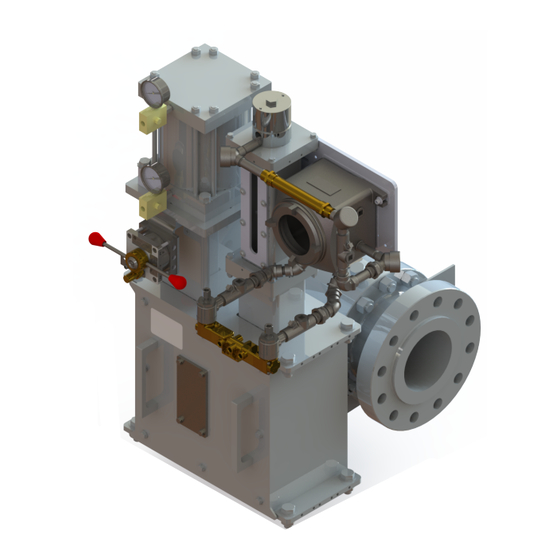
Page 69: Figure 40 Dngp With 5/3 Solenoid Attached
250 psi, however, the external pilot pressure range MUST be 50 psi to 160 psi. Note: 1/2” NPT or higher pressure versions may be available - please, consult factory. © 2022 Baker Hughes Company. All rights reserved. Becker Digital Natural Gas Positioner Instruction Manual | 69... - Page 70 This page intentionally left blank. 70 | Baker Hughes © 2022 Baker Hughes Company. All rights reserved.
-
Page 71: Software Functionality
W = Waking (Solenoids on, Not Yet Moving D = Decreasing Current, Bypass Limit M = Moving i = Increasing Current C = Coasting I = Increasing Current, Bypass Limit © 2022 Baker Hughes Company. All rights reserved. Becker Digital Natural Gas Positioner Instruction Manual | 71... -
Page 72: Digital Mode
W = Waking (Solenoids on, Not Yet Moving D = Decreasing Current, Bypass Limit M = Moving i = Increasing Current C = Coasting I = Increasing Current, Bypass Limit 72 | Baker Hughes © 2022 Baker Hughes Company. All rights reserved. -
Page 73: Input Configuration Menu
ENTER button then press ENTER button press ENTER button press ENTER button Upper Split Limit Lower Split Limit 16 mA 12 mA © 2022 Baker Hughes Company. All rights reserved. Becker Digital Natural Gas Positioner Instruction Manual | 73... -
Page 74: Valve Actions Menu
ENTER button then press ENTER button then press ENTER button Default Values Threshold: On Time: 70 ms Off Time: 80 ms *Setting Threshold to 0% disables Pulse Mode 74 | Baker Hughes © 2022 Baker Hughes Company. All rights reserved. -
Page 75: Logging And Alarms Menu
Press UP or DOWN Press UP or DOWN button to adjust button adjust value value then press then press ENTER ENTER button button © 2022 Baker Hughes Company. All rights reserved. Becker Digital Natural Gas Positioner Instruction Manual | 75... -
Page 76: Remote Indicator
Press UP or DOWN button to select LOGGING & to select RESET SOLENOID to select YES, then press ALARMS, then press COUNT, then press ENTER ENTER button ENTER button button 76 | Baker Hughes © 2022 Baker Hughes Company. All rights reserved. -
Page 77: Firmware Menu
FIRMWARE, then to select VERSION INFO, to select VERSION INFO, press ENTER button then press ENTER button then press ENTER button © 2022 Baker Hughes Company. All rights reserved. Becker Digital Natural Gas Positioner Instruction Manual | 77... - Page 78 This page intentionally left blank. 78 | Baker Hughes © 2022 Baker Hughes Company. All rights reserved.
-
Page 79: Troubleshooting And Maintenance
# 5 and 6 instead. Checks the SCADA for internal power or external power. Check the DNGP board JP1 for external or internal power. © 2022 Baker Hughes Company. All rights reserved. Becker Digital Natural Gas Positioner Instruction Manual | 79... - Page 80 • For 24 VDC: If below 58-65 Ohms, the solenoid is shorted. • For 12 VDC: If below 14-17 Ohms, the solenoid is shorted. Change the solenoid coils. See spare parts list for coil part number 80 | Baker Hughes © 2022 Baker Hughes Company. All rights reserved.
-
Page 81: Dngp Leak Test Procedure
Insert the new electronic module back on the transmitter housing, connect the four wires and turn the power to On. Insert the two screws with hex wrench, connect the wires and power the unit . © 2022 Baker Hughes Company. All rights reserved. Becker Digital Natural Gas Positioner Instruction Manual | 81... -
Page 82: Valve Maintenance Instructions
Depending on the medium and service conditions, periodic inspection of internal valve parts for damage or excessive wear is recommended. Thoroughly clean all parts. Replace any worn or damaged parts. 82 | Baker Hughes © 2022 Baker Hughes Company. All rights reserved. -
Page 83: Causes Of Improper Operation
Voltage: Check voltage across the solenoid leads. Voltage must be at least 85% or rated voltage. © 2022 Baker Hughes Company. All rights reserved. Becker Digital Natural Gas Positioner Instruction Manual | 83... - Page 84 Copyright 2022 Baker Hughes Company. All rights reserved. Baker Hughes provides this information on an “as is” basis for general information purposes. Baker Hughes does not make any representation as to the accuracy or completeness of the information and makes no warranties of any kind, specific, implied or oral, to the fullest extent permissible by law, including those of merchantability and fitness for a particular purpose or use.
Need help?
Do you have a question about the Becker Series and is the answer not in the manual?
Questions and answers