Sign In
Upload
Manuals
Brands
Baker Hughes Manuals
Valve Positioners
Becker Series
Baker Hughes Becker Series Manuals
Manuals and User Guides for Baker Hughes Becker Series. We have
1
Baker Hughes Becker Series manual available for free PDF download: Instruction Manual
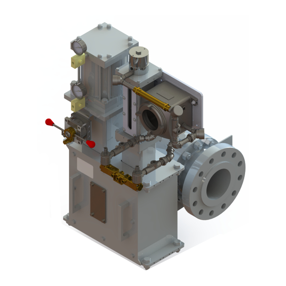
Baker Hughes Becker Series Instruction Manual (84 pages)
Digital Natural Gas Positioner (DNGP) Series 3.5 M with Modbus Protocol
Brand:
Baker Hughes
| Category:
Valve Positioners
| Size: 17.34 MB
Table of Contents
Table of Contents
5
Safety Information
9
Documentation Symbols
9
DNGP Product Safety
10
Introduction
13
Principle of Operation
13
Scope of Manual
13
Technical Assistance
13
Specifications
15
Technical Specifications
15
Table 1 DNGP Technical Specifications
15
Table 2 Rotary Transmitter Technical Specifications
17
Table 3 Programmable Linear Position Transmitter Specifications (Supplied 2006 and Later)
17
Table 4 DNGP Spare Parts List
18
Certifications and Approvals
19
Table 5 Certifications and Approvals
19
Software Release Information
20
Table 6 Software Release Information
20
Installation
21
Mounting
21
DNGP (Aluminum Enclosure)
21
DNGP-REM (Plastic Enclosure)
21
Wire Size Recommendations
22
Figure 1 DNGP-EXP Aluminum Enclosure and 5/3 Solenoid Valve
23
Figure 2 DNGP-REM (Plastic Enclosure)
23
Table 7 Wire Size, Wire Resistance and Voltage Drop Information1
23
Logic Board and Wiring Diagram
24
Figure 3 Terminal Board #1 (10 Pins) and Terminal Board #2 (14 Pins)
24
Jumpers and Fuses
25
Figure 4 DNGP Logic Board Layout
25
Orifice Adjustment
26
Figure 5 Variable Orifice Assembly (Standard Assembly Shown)
26
Figure 6 2" and 3" Valves Configuration
27
Table 8 Orifice Part Numbers
28
Figure 7 4" to 12" Valves Configuration
29
Figure 8 Valves Greater than 16" Configuration
30
Figure 9 Single-Acting Control Valve, PSUPPLY ≥ 50 PSIG
31
Figure 10 Single-Acting Control Valve, PSUPPLY < 55 PSIG
32
Electro-Pneumatic Positioner Pressure Control Override
33
Figure 11 Conventional Flow Control with Pressure Control Override (PCO)
33
Figure 12 Flow Control with Electro-Pneumatic Positioner and PCOH High Pressure Override
34
Figure 13 Double-Acting Control Valve with PCO, PSUPPLY ≥ 55 PSIG (High Pressure Override)
35
Figure 14 Double-Acting Control Valve with PCO, PSUPPLY > 55 PSIG
36
Figure 15 Single-Acting Control Valve with PCO, PSUPPLY≤60 PSIG
37
Figure 16 Single-Acting Control Valve with PCO, PSUPPLY > 55 PSIG
38
Figure 17 Rotary Piston Spring to Close Actuator W/High Pressure 3/2 Solenoid Valve, PSUPPLY 65-160 PSIG
39
Figure 18 Rotary Piston Spring to Open Actuator W/Pressure Control Override, PSUPPLY 65-160 PSIG
40
Figure 19 Rotary Piston Spring Return Actuator W/Snap Acting Selector Relay, PSUPPLY 65-160 PSIG for Short Dynamic Systems such as Power Plants
41
DNGP with Position Transmitter
43
Westlock CS and DS Rotary Position Transmitters
43
Figure 20 Overall Dimensions of Rotary Transmitter
43
Wiring Diagram for Westlock CS and DNGP
44
Jumper Settings for DNGP with Rotary Transmitter CS
44
Figure 21 Rotary Transmitter Wiring Diagram CS
44
Rotary Transmitter 4-20 Ma Calibration Procedure for CS
45
Figure 22 Components of Rotary Transmitter for Calibration Procedure
45
Wiring Diagram for Westlock DS and DNGP
46
Figure 23 Rotary Transmitter Wiring Diagram DS
46
Rotary Transmitter 4-20 Ma Calibration Procedure for DS
47
DNGP with Balluff Linear Transmitter
51
Figure 24 DNGP and Linear Transmitter Tail Rod Configuration for Legacy Actuators
51
Figure 25 Detailed View of Linear Position Transmitter Tail Rod Transducer for Legacy Actuators
51
Figure 26 Detailed View of the Linear Position Transmitter Standard Assembly for Legacy Actuators
52
Table 9 Tail Rod/Proportional Configuration Part Numbers for Legacy Actuators
52
Table 10 Riser Pipe Mount Configuration Part Numbers for Legacy Actuators
53
Figure 27 Linear Transmitter Overall Dimensions
54
Figure 28 Linear Transmitter Adapter Flange and Magnet for Legacy Actuators
54
Figure 29 Reversible Linear Transmitter Connector
55
Figure 30 Linear Transmitter Wiring Diagram for BTL3
56
Figure 31 Programmable Linear Transmitter Wiring Diagram for BTL5 and BTL7
57
Figure 32 Linear Transmitter BTL5 and BTL7
58
BTL5 Position Sensor Configuring DNGP Positioner Action
59
Calibrating the Linear Position Transmitter BTL5
60
Figure 33 Linear Transmitter BTL5 DIP Switch Location
60
Figure 34 Linear Transmitter Assembly with Programming Tool (BTL5)
60
Calibrating the Linear Position Transmitter BTL7
61
Figure 35 BTL7 Wiring and External View
61
Installation of Calibration Tool on BTL7
62
Figure 36 Linear Transmitter Assembly with Programming Tool (BTL7)
62
Calibration BTL7
63
Fine Adjustment of End Points
65
How to Reset BLT7
66
Replacement Parts for BTL Position Transmitters
66
Table 11 Transmitter Parts for Legacy Actuators
66
Table 12 Transmitter Parts for Refresh Actuators
66
DNGP Accessories
67
Low Pressure 2/2 Solenoid Valve for Power Gas < 40 PSIG
67
Figure 37 Low Pressure 2/2 Solenoid Overall Dimensions
67
Figure 38 DNGP with 2/2 Solenoid Valves
67
High Pressure 3/2 Solenoid Valve for Power Gas 60 - 160 PSIG
68
High Pressure 5/2 Solenoid Valve for Power Gas 60 - 160 PSIG
68
Figure 39 High Pressure 3/2 Solenoid Valve (60 - 160 PSIG)
68
Figure 40 DNGP with 5/3 Solenoid Attached
69
Figure 41 High Pressure 5/3 Solenoid Overall Dimensions
69
Software Functionality
71
Run Time Screen
71
Current Loop Mode
71
Digital Mode
72
Input Configuration Menu
73
Input Select
73
Split Control
73
Valve Actions Menu
74
Bypass Mode
74
Pulse Mode
74
Logging and Alarms Menu
75
Limit Alarms
75
Remote Indicator
76
Reset Solenoid Counter
76
Firmware Menu
77
Version Info
77
Troubleshooting and Maintenance
79
Troubleshooting the Firmware Cold Restart
79
Alarm and Fault Handling
79
Table 13 DNGP Alarm and Fault Handling
79
DNGP Leak Test Procedure
81
Replacing the Electronic Module of the Programmable Linear Transmitter
81
Valve Maintenance Instructions
82
Gas Line Filter
82
2/2 and 3/2 Solenoid Valve Maintenance and Troubleshooting Instructions
82
Cleaning
82
Preventative Maintenance
82
Causes of Improper Operation
83
Advertisement
Advertisement
Related Products
Baker Hughes Bently Nevada Ranger Pro
Baker Hughes Masoneilan 47 E Series
Baker Hughes Masoneilan 47 P Series
Baker Hughes Masoneilan 4700E
Baker Hughes Masoneilan 4700P
Baker Hughes Masoneilan 4800E
Baker Hughes Masoneilan 4800P
Baker Hughes Masoneilan 51 Series
Baker Hughes Masoneilan 52 Series
Baker Hughes Masoneilan 53 Series
Baker Hughes Categories
Control Unit
Measuring Instruments
Valve Positioners
Controller
Test Equipment
More Baker Hughes Manuals
Login
Sign In
OR
Sign in with Facebook
Sign in with Google
Upload manual
Upload from disk
Upload from URL