Baker Hughes Masoneilan SVI3 Instruction Manual
Digital positioner advanced performance
Hide thumbs
Also See for Masoneilan SVI3:
- Instruction manual (123 pages) ,
- Quick start manual (24 pages) ,
- Special instructions manual (14 pages)
Table of Contents
Advertisement
Quick Links
Advertisement
Table of Contents

Subscribe to Our Youtube Channel
Related Manuals for Baker Hughes Masoneilan SVI3


Summary of Contents for Baker Hughes Masoneilan SVI3
- Page 1 3 Digital Positioner ™ Advanced Performance Instruction Manual (Rev. E)
- Page 2 OR SHOULD PARTICULAR PROBLEMS ARISE WHICH ARE NOT COVERED SUFFICIENTLY FOR THE CUSTOMER/OPERATOR’S PURPOSES THE MATTER SHOULD BE REFERRED TO BAKER HUGHES. THE RIGHTS, OBLIGATIONS AND LIABILITIES OF BAKER HUGHES AND THE CUSTOMER/OPERATOR ARE STRICTLY LIMITED TO THOSE EXPRESSLY PROVIDED IN THE CONTRACT RELATING TO THE SUPPLY OF THE EQUIPMENT.
- Page 3 C / 04-2021 Updated Explosion proof marking from EEx d to Ex d. Stainless Steel housing option and spare parts kits added for Marine applications. © 2023 Baker Hughes Company. All rights reserved. Masoneilan SVI3 Installation and Maintenance Manual | 3...
-
Page 4: Table Of Contents
3.4.3 Special Cases ........................ 30 3.4.4 Mounting the SVI3 on Reciprocating Valves ..............30 ..................34 ......................................................................... 36 ............. 36 ......................36 ..................................... 38 4 | Baker Hughes © 2023 Baker Hughes Company. All rights reserved. - Page 5 4.4.3 Run Find Stops ..............................................................4.4.6 View and Clear Faults ............................................................................................................................................................................................. 6.1.1 Storage ................................................. 6.1.3 Handling ......................... 6.1.4 Disposal ............................................© 2023 Baker Hughes Company. All rights reserved.
- Page 6 ................... 112 ......................112 ................ 113 ........................113 ..................................................116 ........................116 ................................................................................................................... 120 ....................120 ................... 121 ................123 ........................123 6 | Baker Hughes © 2023 Baker Hughes Company. All rights reserved.
- Page 7 Indicates a potentially hazardous situation, which if not avoided could result in property damage or data loss. Note: Indicates important facts and conditions. 1.2 SVI3 Product Safety local and national compressed air and instrumentation codes. © 2023 Baker Hughes Company. All rights reserved.
- Page 8 • Installed, put into service, used and maintained in compliance with national and local regulations and in accordance with the recommendations contained in the relevant standards concerning temperature. 8 | Baker Hughes © 2023 Baker Hughes Company. All rights reserved.
- Page 9 Failure to adhere to the requirements listed in this manual can cause loss of life and property. Before installing, using, or carrying out any maintenance tasks associated with this instrument, READ THE INSTRUCTIONS CAREFULLY. © 2023 Baker Hughes Company. All rights reserved.
- Page 10 Note: The SVI3 Digital Valve Positioner is designed to operate with clean, dry, oil-free, instrument grade air to ANSI-ISA-57.3 1975 (R1981) or ISA-S7.3-1975 (R1981) or with a sweet natural gas supply. 10 | Baker Hughes © 2023 Baker Hughes Company. All rights reserved.
- Page 11 • Comply with national and local explosive atmosphere regulations. • instrument or make sure that the locale conditions for potentially explosive atmosphere permit the safe opening of the cover. © 2023 Baker Hughes Company. All rights reserved. Masoneilan SVI3 Installation and Maintenance Manual | 11...
-
Page 12: Conventions Used In This Manual
Indicates a potentially hazardous situation, which if not avoided could result in property or data damage. Indicates a potentially hazardous situation, which if not avoided could result in serious injury. 12 | Baker Hughes © 2023 Baker Hughes Company. All rights reserved. -
Page 13: Related Documentation For The Svi3
1.4 Related Documentation for the SVI3 are available in Resource Center: https://valves.bakerhughes.com/resource-center Software Manual (Ref. 31426). 1.4.1 Masoneilan Help Contacts © 2023 Baker Hughes Company. All rights reserved. Masoneilan SVI3 Installation and Maintenance Manual | 13... - Page 14 14 | Baker Hughes © 2023 Baker Hughes Company. All rights reserved.
-
Page 15: Introduction
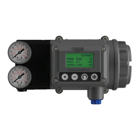
2.1 Overview The Masoneilan™ SVI3 is a high performance, HART ® Registered host ® The SVI3 DTM and ValVue3 Masoneilan’s software facilitates control valve setup and diagnostics. Figure 1 - SVI3 Positioner © 2023 Baker Hughes Company. All rights reserved. -
Page 16: Svi3 Features
• Optional Exhaust Routing Manifold to capture all exhaust and vent gas for • Automated Valve Commissioning routing to safe location Reciprocating Valves Aluminum housing Open Actuators Electronics 16 | Baker Hughes © 2023 Baker Hughes Company. All rights reserved. - Page 17 Input Current, 4 to 20 mA Electronics Filter Flow Regulator HART Current to Converter Characteriscs Diagnoscs Coupled Actuator Figure 2 - Block Diagram with I/P Converter and Pressure Sensor © 2023 Baker Hughes Company. All rights reserved.
-
Page 18: Main Electronics Module
The temperature sensor reading is used 2.3.3 Pneumatic Module 2.3.3.1 Pressure Sensor 2.3.3.2 Current-to-Pressure Converter, I/P increase in the coil current. Encapsulation of the coil provides protection from the environment. 18 | Baker Hughes © 2023 Baker Hughes Company. All rights reserved. - Page 19 2.3.3.3 Single Acting Pneumatic Relay Pneumatic module Figure 3 - SVI3 Pneumatic Module with Single Acting Relay 2.3.4 Optional Display Module with Pushbuttons hand-held communicator. These switches perform generic ® 2.3.5 Options Module © 2023 Baker Hughes Company. All rights reserved.
-
Page 20: Valvue Software
• Trend setpoint, valve position, (clone device) actuator pressure 2.4.2 Masoneilan Software Download Refer to SVI3 DTM & Software manual to download and install the software. 2.5 Advanced and Online Diagnostics 20 | Baker Hughes © 2023 Baker Hughes Company. All rights reserved. -
Page 21: Svi3 Installation And Set Up
3. SVI3 Installation and Set Up 3.1 Physical Dimensions User Interface module module Main electronics Options Threaded module end cover Figure 4 - SVI3 Components © 2023 Baker Hughes Company. All rights reserved. Masoneilan SVI3 Installation and Maintenance Manual | 21... -
Page 22: Svi3 Dimensions
3.1.1 SVI3 Dimensions Figure 5 - SVI3 Single-Acting Dimensions 22 | Baker Hughes © 2023 Baker Hughes Company. All rights reserved. -
Page 23: Installation Steps
Reference page 30 for instructions for instructions ed to the valve actuator. page 30 for instructions. for instructions. (optional). Valvue3/AMS HART Communicator/AMS. instructions ® © 2023 Baker Hughes Company. All rights reserved. Masoneilan SVI3 Installation and Maintenance Manual | 23... - Page 24 Figure 6 - Sample Rotary Installation 87/88 Series Actuator with an SVI3 mounted as an example of a reciprocating installation Mounting Output to Actuator Air Set Figure 7 - Sample Reciprocating Installation 24 | Baker Hughes © 2023 Baker Hughes Company. All rights reserved.
- Page 25 Do not remove the instrument cover or connect to an electrical circuit in a Hazardous Area unless power is disconnected. • Valve Air to Open (ATO) or Air to Close (ATC) • Actuator pressure rating © 2023 Baker Hughes Company. All rights reserved.
- Page 26 Long end of bracket to left (preferred) Air-to-Open Air-to-close (ATC) Set magnet when actuator is energized Magnet Axis Magnet Axis Long end of bracket to left (preferred) Air-to-Open 26 | Baker Hughes © 2023 Baker Hughes Company. All rights reserved.
- Page 27 SVI3 digital valve positioner. During hydrostatic testing the shaft is thrust 4. Slide the magnet holder into the extension shaft. The location of the magnets is in the ring of the © 2023 Baker Hughes Company. All rights reserved.
- Page 28 >60° Rotation Full Open or Counter Clockwise Full Closed rotation with increasing setpoint 0 +/- 1000 for other con- rotation Clockwise or Travel counterclockwise (Mid-Stroke) (0°) 28 | Baker Hughes © 2023 Baker Hughes Company. All rights reserved.
- Page 29 • Ensure that the V-Seal makes contact with the skirt around the position sensor protrusion on SVI3 housing. 3.4.2.1 Checking the Magnet • Use SVI3 DTM with Valvue3 to check the magnet 3.4.2.2 Performing a Visual Inspection © 2023 Baker Hughes Company. All rights reserved.
-
Page 30: Special Cases
• Actuator pressure rating Head Screw Driver ® 3.4.4.1 Mounting the SVI3 on a Reciprocating Actuator The SVI3 mounting assumes that the actuator is in the normal upright position. 30 | Baker Hughes © 2023 Baker Hughes Company. All rights reserved. - Page 31 Table 3 - Reciprocating Valve Mounting Hole and Turnbuckle Length Actuator Size Mounting Lever Turnbuckle Stroke Masoneilan Hole Hole Length 6 and 10 (20.32 - 38.1 mm) (20.32 - 38.1 mm) © 2023 Baker Hughes Company. All rights reserved. Masoneilan SVI3 Installation and Maintenance Manual | 31...
- Page 32 4. Select mounting hole A, B, C or D for the stroke of the valve. For example, hole B is Figure 12 - Lever for Model 87/88 Multispring Actuator • Retract, actuators vent the actuator of air pressure. ® 32 | Baker Hughes © 2023 Baker Hughes Company. All rights reserved.
- Page 33 3.4.4.2 Using SVI3 DTM with Valvue3 to Check Magnet Position 1. Refer to DTM Manual for connection procedure. for a reciprocating valve. © 2023 Baker Hughes Company. All rights reserved. Masoneilan SVI3 Installation and Maintenance Manual | 33...
- Page 34 Performing a Visual Inspection 3.5 Connecting the Tubing and Air Supply positioner. Figure 14 - SVI3 Air Ports on Single Acting Positioner 34 | Baker Hughes © 2023 Baker Hughes Company. All rights reserved.
- Page 35 Explosion Proof Conduit Fittings must be used for wiring ports. During Operation, None of the electrical contacts can be Figure 15 - Single Acting SVI3 Gas Vents information, refer to Instructions Manual Ref. 34633. © 2023 Baker Hughes Company. All rights reserved.
- Page 36 • For details and calculation methods for wiring resistance, and capacitance and for calculation of ® the current, not the voltage. 36 | Baker Hughes © 2023 Baker Hughes Company. All rights reserved.
- Page 37 - Ensure the control loop is powered while making make measurements with a meter. 3.6.3 Connecting to the Control Loop Main Terminal connections must be wired using a nominal torque of 1.13 N-m. End Cover Covers Figure 16 - SVI3 Electrical Gland/Conduit Entries ® © 2023 Baker Hughes Company. All rights reserved.
- Page 38 For proper operation, maintain signal polarity + and - respectively. Options Board Terminal connections must be wired using a wire of 26 AWG to 14 AWG size and terminal torque between 0.5 - 0.6 Nm. 38 | Baker Hughes © 2023 Baker Hughes Company. All rights reserved.
- Page 39 2. Thread the wire through the gland which was installed during the Control loop connection. screw. DI Connections Connections to the non-Masoneilan devices depend on their documentation. SVI3 REMOTE 1-5Vdc 4-20mA OUT SW #2 SW #1 Figure 19 - DI Connections © 2023 Baker Hughes Company. All rights reserved.
- Page 40 Switch ON 30 VDC max. ≤ 1 V (Switch saturation voltage) ≤ 0.200 mA (Switch leakage current) 1 A max. For IS Applications, Maximum Switch Current allowed is 125mA. 40 | Baker Hughes © 2023 Baker Hughes Company. All rights reserved.
- Page 41 Sample Switch Connection with Inductive load SVI3 REMOTE 1-5Vdc 4-20mA OUT SW #2 SW #1 External Voltage limit current to <1A Source 24VDC © 2023 Baker Hughes Company. All rights reserved. Masoneilan SVI3 Installation and Maintenance Manual | 41...
- Page 42 Connections to the non-Masoneilan devices depend on their documentation. SVI3 REMOTE 1-5Vdc 4-20mA OUT SW #2 SW #1 4-20mA Input Voltage Source 24V Figure 23 - Retransmit Connections 42 | Baker Hughes © 2023 Baker Hughes Company. All rights reserved.
- Page 43 4 - 20 mA, and cannot have a voltage source applied to its input terminals. The following will not cover all the details for a successful installation, in all cases. That is 3.6.5.1 SVI3 Setup © 2023 Baker Hughes Company. All rights reserved. Masoneilan SVI3 Installation and Maintenance Manual | 43...
- Page 44 (-) not function. Area Area SVI3 HandHeld HART Communicator Computer REMOTE 1-5Vdc HART 4-20mA OUT SW #2 SW #1 Modem HART Compliant 4-20mA Output 44 | Baker Hughes © 2023 Baker Hughes Company. All rights reserved.
- Page 45 The internal electronics are isolated from ground. Grounding the case is unnecessary necessary to conform to local codes. 3.6.5.3 Compliance Voltage in Single Drop Current Mode MORE voltage higher current that complements the 9 V at 20 mA. See © 2023 Baker Hughes Company. All rights reserved.
- Page 46 Table 6 - Compliance Voltage for No Barrier with HART®Filter and Resistor and 18 AWG Cable Voltage at SVI3 at 20mA Drop in 220 Ohm resistor 4.4 V 0.6 V HART 2.3 V Drop in passive Filter ® 16.3 V Conclusion 46 | Baker Hughes © 2023 Baker Hughes Company. All rights reserved.
- Page 47 • Closed the actuator is ATO. • Open it is ATC. 3.7.1.2 Actuator Action is open 100% at 4 mA and closed 0% at 20 mA. The graph shows the valve movement and actuator © 2023 Baker Hughes Company. All rights reserved.
- Page 48 Figure 27 - ATO and ATC Action with Linear Positioner Characteristics 48 | Baker Hughes © 2023 Baker Hughes Company. All rights reserved.
- Page 49 Figure 28 - ATO and ATC Action in Percentage of Positioner Characteristics © 2023 Baker Hughes Company. All rights reserved.
- Page 50 3.7.2 Before Powering Up on page 89. 3.7.3 Powering Up the SVI3 Communicator. © 2023 Baker Hughes Company. All rights reserved.
- Page 51 •SVI3 DTM with Valvue3 ® 4.1.1 SVI3 DTM with Valvue 4.1.2 SVI3 DD for HART Communicators 4.1.3 Local Display and Pushbuttons mounted on the SVI3. pressure and position information. © 2023 Baker Hughes Company. All rights reserved.
- Page 52 The SVI3 has an additional function called Smart Cal. This function Smart with an optimal set of operating Cal/Back 4.3.1 Pushbuttons • menu, or to increase at a faster rate. • • seconds • © 2023 Baker Hughes Company. All rights reserved.
- Page 53 (Back) /Back Figure 29 - SVI3 Display Note: An exclamation point (!) in the SVI3 display window indicates that there is instrument refer to the appears. Refer to the 4.3.2 NAMUR Status © 2023 Baker Hughes Company. All rights reserved.
- Page 54 Maintenance required: restricted due to operational conditions the unlocked mode. See SVI3 DTM Manual for more details. , after initial setup, to lock the Table 7 - Pushbutton Lock Security Level Level Access © 2023 Baker Hughes Company. All rights reserved.
- Page 55 4.3.5 Perform Smart Cal SMART CAL a maximum of seven. Hold for the Smart Cal Release to start the Smart Cal. 3. Release the CAUTION © 2023 Baker Hughes Company. All rights reserved.
- Page 56 VIEW VIEW CONFIG CALIB Clear DATA ERRors Menu Menu Errors MENU Menu Figure 31 - NORMAL Operation and MANUAL Menu Structures © 2023 Baker Hughes Company. All rights reserved.
- Page 57 1. If in the NORMAL VIEW DATA menu. (This leaves the valve in NORMAL mode.) If in mode, VIEW DATA mode. 4. To exit from the VIEW DATA . You return to the last menu © 2023 Baker Hughes Company. All rights reserved.
- Page 58 See Full Menu Structure ATO or ATC Figure 32 - VIEW DATA Menu 4.3.8 VIEW ERR Diagnostics Messages information. CLR ERR on either the MANUAL or NORMAL mode menus. Exiting from the © 2023 Baker Hughes Company. All rights reserved.
- Page 59 NORMAL appears. MANUAL appears. NORMAL appears. NORMAL mode and normal operation. to changes in set point input signal and the values displayed change in accordance with changes in the input signal. When Air- © 2023 Baker Hughes Company. All rights reserved.
- Page 60 Press * to accept new value and proceed to QUICK50 CUSTOM using DTM to setup custom valve characteristics 4.3.9.1 Valve Characteristics and valve position. This is called the position characteristic. characteristics. valve appli- using SVI3 DTM. 60 | Baker Hughes © 2023 Baker Hughes Company. All rights reserved.
- Page 61 Table 8 - Guidelines for Characteristic Choice Valve Type and Built In Characteristic Desired Installed Valve Standard Positioner Position Characteristic Characteristic Selection EQ% CAMFX (when Varimax Varimax TRIM TRIM © 2023 Baker Hughes Company. All rights reserved. Masoneilan SVI3 Installation and Maintenance Manual | 61...
- Page 62 TS value, SVI3 moves the valve to the TS position value. SVI3 applies maximum actuator force. example, then the - to decrease TS. 62 | Baker Hughes © 2023 Baker Hughes Company. All rights reserved.
- Page 63 STEP 3/3 TUNE ERR STOPS FAIL Figure 34 - Calibration Menu © 2023 Baker Hughes Company. All rights reserved. Masoneilan SVI3 Installation and Maintenance Manual | 63...
- Page 64 POS and SIGNAL indicating POS –M and SIG indicating MANUAL mode. MANUAL MANUAL menu. SETUP. SETUP mode. 6. In SETUP CONFIG CALI STOPS appears. CALIB FIND STOPS. 64 | Baker Hughes © 2023 Baker Hughes Company. All rights reserved.
- Page 65 DO NOT perform Auto Tune while the valve is controlling the process. 4.3.11 Adjust Input Signal Range (ATC) position SIG LO of the valve. • Correct, press + to advance to the next item. © 2023 Baker Hughes Company. All rights reserved.
- Page 66 RESET no longer appears. VIEW ERR. messages in turn. 3. Move to MANUAL menu and enter Manual mode. 4. Select RESET to start the valve from its failsafe condition. removing error 66 | Baker Hughes © 2023 Baker Hughes Company. All rights reserved.
- Page 67 0% if ATO, 100% if ATC. You can set a that forces the valve to its failsafe critical loops to force the process to trip if the © 2023 Baker Hughes Company. All rights reserved.
- Page 68 ® circuit except on the safe area side of the barrier. Do not operate a PC in a hazardous area without compliance to local and plant regulations. 68 | Baker Hughes © 2023 Baker Hughes Company. All rights reserved.
- Page 69 4.4.1 SVI3 DD Menu Structure © 2023 Baker Hughes Company. All rights reserved.
- Page 70 Setup. 4.4.5 Run Diagnostics 1. Open HART screen and tap Online. 2. Tap Status/Diagnostics. 3. Tap Signature. 4. Tap Run Diagnostics. You are led through a series of screens run the process. © 2023 Baker Hughes Company. All rights reserved.
- Page 71 • Clear Current Faults to clear the faults. The faults will reoccur if the cause is not • Historical Faults to view all faults current and past. • Clear All Faults to clear current and historical faults. © 2023 Baker Hughes Company. All rights reserved.
- Page 72 © 2023 Baker Hughes Company. All rights reserved.
- Page 73 5. Maintenance and Troubleshooting 5.1 SVI3 Maintenance and Repair • Remove and install the cover, 5.1.1 Repair also mounting screws and O- parts are permitted. © 2023 Baker Hughes Company. All rights reserved.
- Page 74 5.1.2 Spare Parts Table 9 - Spare Parts Part Number Description Exhaust Routing Manifold Kit, SVI3 © 2023 Baker Hughes Company. All rights reserved.
- Page 75 SVI3 User Interface Kit Replacement SVI3 Threaded end cover Replacement SVI3 Pneumatic Module Replacement Standard temperature Low (Arctic) temperature SVI3 Conduit Entry Plug Replacement SVI3 Electronics Module Replacement Standard temperature Low (Arctic) temperature © 2023 Baker Hughes Company. All rights reserved.
- Page 76 © 2023 Baker Hughes Company. All rights reserved.
- Page 77 © 2023 Baker Hughes Company. All rights reserved.
- Page 78 © 2023 Baker Hughes Company. All rights reserved.
- Page 79 © 2023 Baker Hughes Company. All rights reserved.
- Page 80 80 | Baker Hughes © 2023 Baker Hughes Company. All rights reserved.
- Page 81 © 2023 Baker Hughes Company. All rights reserved. Masoneilan SVI3 Installation and Maintenance Manual | 81...
- Page 82 82 | Baker Hughes © 2023 Baker Hughes Company. All rights reserved.
- Page 83 © 2023 Baker Hughes Company. All rights reserved. Masoneilan SVI3 Installation and Maintenance Manual | 83...
- Page 84 84 | Baker Hughes © 2023 Baker Hughes Company. All rights reserved.
- Page 85 © 2023 Baker Hughes Company. All rights reserved.
- Page 86 86 | Baker Hughes © 2023 Baker Hughes Company. All rights reserved.
- Page 87 © 2023 Baker Hughes Company. All rights reserved.
- Page 88 88 | Baker Hughes © 2023 Baker Hughes Company. All rights reserved.
- Page 89 Insulation Resistance MTBF Electrostatic Fast Transient Burst - Exposed circuits covered with anti-fungal coating © 2023 Baker Hughes Company. All rights reserved.
- Page 90 60 to 100% of actual stop Start Up Time (from no power) Minimum current to maintain HART 3.2 mA ® HART For Single Acting. ® © 2023 Baker Hughes Company. All rights reserved.
- Page 91 Minimum Current Signal to Start Up 3.2 mA Impedance Range Minimum Input Span for Split Range Operation Upper Range Value for Split Range Operation (4 mm to .34 mm to .14 mm Digital Communication nine alphanumeric characters. © 2023 Baker Hughes Company. All rights reserved.
- Page 92 Table 15 - Pneumatics Single Acting Standard Flow S content not more than 20 ppm Action Direct Acting Do not exceed actuator rating. Air Consumption failure. Output drops to low pressure. Yes, with optional manifold kit © 2023 Baker Hughes Company. All rights reserved.
- Page 93 Integrates with leading DCSs with full DTM and EDD support, • Baker Hughes / Valvue3 • Emerson DeltaV / AMS Diagnostics Table 17 - HART Device Information ® Item SVI3 Device Revision © 2023 Baker Hughes Company. All rights reserved.
- Page 94 DO Switch 2 Temperature degC Volts Input Raw Counts Valve Strokes Direction Changes Friction Stroke Time Open Stroke Time Close High Spring Range Reserved Stick Slip Amplitude Stick Slip Ratio RMSError Device Mode © 2023 Baker Hughes Company. All rights reserved.
- Page 95 6.1.1 Storage • Do not allow standing water to accumulate. 6.1.2 Protection actuator. 6.1.3 Handling 6.1.4 Disposal management options. 6.1.5 SVI3 Model Numbering © 2023 Baker Hughes Company. All rights reserved.
- Page 96 If you have bought SVI3 Unit with Part Number SVI3-XXXXXX13, AUTHORIZED CONTACT Baker Hughes, room 22 If you have bought SVI3 Unit with Part Number SVI3-XXXXXX12, Markings Intrinsic Safety IIIC T C Da Increased Safety/Non-Incendive Protection by Enclosure © 2023 Baker Hughes Company. All rights reserved.
- Page 97 Table 19 - Model and feature comparison Device Diagnostic Level Diagnostic Description Type Standard Advanced Online Valve Time Open Time Closed Accumulated Valve Strokes Stroke time Open Stroke time Closed Measurements (Online) Temperature Min Temperature Max Temperature © 2023 Baker Hughes Company. All rights reserved.
- Page 98 Methods and Ramp Test Standard Valve Signature Extended Valve Signature Signature Storage Friction RMS Error Upper Spring Range Stick Slip - Flag Online Valve Diagnostics Amplitude of Slip in Stick Slip (Online) © 2023 Baker Hughes Company. All rights reserved.
- Page 99 A negative value over-shoot. The recommended values for Aggressiveness is 0 for control valves the the needle valve then open 1 or 2 turns response and less overshoot. and more overshoot. all future user-changed. © 2023 Baker Hughes Company. All rights reserved.
- Page 100 Rise Time Overshoot Settling Time Increase Decrease Increase Decrease Increase Decrease Value Value Value Value Value Value Decrease Increase Increase Decrease Decrease Increase Decrease Increase Decrease Increase Decrease Increase 100 | Baker Hughes © 2023 Baker Hughes Company. All rights reserved.
- Page 101 • Increase I • Add Dead Zone • P term too low, If Actuator is very large 00; if it is . In Setup mode © 2023 Baker Hughes Company. All rights reserved. Masoneilan SVI3 Installation and Maintenance Manual | 101...
- Page 102 41000 Series VRT™ Full Stack Cage 28000 Series Varilog 7.4 Using SVI3 DTM Diagnostics SVI3 advanced features are simple to use with SVI3 DTM software. The following examples illustrate 102 | Baker Hughes © 2023 Baker Hughes Company. All rights reserved.
- Page 103 7.4.1.2 Data Storage data saved. 7.4.1.3 Interfaces of the DTM, please refer to the DTM Manual. © 2023 Baker Hughes Company. All rights reserved. Masoneilan SVI3 Installation and Maintenance Manual | 103...
- Page 104 Valve Health (DTM) values for investigation. Historical Trend (DTM): 104 | Baker Hughes © 2023 Baker Hughes Company. All rights reserved.
- Page 105 7.4.1.4 Alerts / Limits the diagnostics. © 2023 Baker Hughes Company. All rights reserved.
- Page 106 106 | Baker Hughes © 2023 Baker Hughes Company. All rights reserved.
- Page 107 Spring Range (Lower/Upper): Position and Setpoint Cycling: © 2023 Baker Hughes Company. All rights reserved.
- Page 108 108 | Baker Hughes © 2023 Baker Hughes Company. All rights reserved.
- Page 109 • Time near closed 7.4.3 Monitoring a Valve Bellows Seal 7.4.4 Critical Service, Cavitation Control Trim 7.4.5 Diagnostic Valve Tests The standard diagnostic test performs a full stroke test, and determines stroking speed. The Step © 2023 Baker Hughes Company. All rights reserved.
- Page 110 7.5.1 Compliance Test Setup 20mA 20mA Read Vdc when Output Card 4-20 mA Figure 37 - Compliance Voltage Test Setup 2. Send 4 mA to the test setup. 110 | Baker Hughes © 2023 Baker Hughes Company. All rights reserved.
- Page 111 7.6.2 Noise Constraints HART digital ® values 1 and 0. wiring practice, such © 2023 Baker Hughes Company. All rights reserved. Masoneilan SVI3 Installation and Maintenance Manual | 111...
- Page 112 DCS vendor to validate this approach. Note: The internal electronic components are isolated from ground. Grounding the case is unnecessary for functional purposes. conform to local Applications. 112 | Baker Hughes © 2023 Baker Hughes Company. All rights reserved.
- Page 113 ® a HART devices on the safe area side ® positioners. A 0 causes HART masters to stop searching for additional positioners. ® © 2023 Baker Hughes Company. All rights reserved. Masoneilan SVI3 Installation and Maintenance Manual | 113...
- Page 114 Computer REMOTE 1-5Vdc Isolator HART 4-20mA OUT SW #2 SW #1 Modem HART Compliant HART Filter 4-20mA Output HART Address 2 Figure 38 - Split Range with Isolator 114 | Baker Hughes © 2023 Baker Hughes Company. All rights reserved.
- Page 115 Table 23 - Supplemental Voltage for Split Range Number of SVI3s on a Current Loop 18.0 VDC 7.7.4 Verify Wiring and Connections • Connect a DC voltmeter across the input terminals. SVI3. source is to SVI3 input. © 2023 Baker Hughes Company. All rights reserved.
- Page 116 Figure 39 - Split Range with Supplemental Power Supply - Non-Hazardous 7.8 HART Communications with Intrinsic Safety 7.8.1 Overview in addition to www.mtl-inst.com or R.Stahl, Inc. www.rstahl.com. codes. • Active galvanic isolators must ® consider HART ® ® 116 | Baker Hughes © 2023 Baker Hughes Company. All rights reserved.
- Page 117 1-5Vdc Barrier Single Channel Resistance HART 4-20mA OUT SW #2 SW #1 Modem HART Compliant HART Filter 4-20mA Output Figure 40 - Intrinsically Safe Installation with Zener Barrier and HART Filter ® © 2023 Baker Hughes Company. All rights reserved.
- Page 118 HART ® ® connections are supported on the safe area side of the isolator. manufacturer for devices rated for use with the SVI3 I. Area Approvals. 118 | Baker Hughes © 2023 Baker Hughes Company. All rights reserved.
- Page 119 ANSI/ISA 84.00.01-2004 (IEC 61511 Mod.) 7.9.2 Terms and Abbreviations of the nominal operation and under single fault condition. demand from the process. presence of faults or errors during the useful life of an instrument. © 2023 Baker Hughes Company. All rights reserved.
- Page 120 7.9.3 Introduction standards. and/or electrical input signal <2.0mA) 7.9.4 SVI3 Device Description normal operation, the SVI3 is positioning the valve in response to setpoint signal from the controller. 120 | Baker Hughes © 2023 Baker Hughes Company. All rights reserved.
- Page 121 The designer of a SIF must check that the product is rated for use within the environmental limits as 7.9.5.3 Application Limits This report details all failure rates and failure modes as well as the expected lifetime. related failure rates. © 2023 Baker Hughes Company. All rights reserved. Masoneilan SVI3 Installation and Maintenance Manual | 121...
- Page 122 7.9.5.6 Connecting the SVI3 to the Controller 7.9.5.7 General Requirements to the fail safe state in less than 100ms upon loss of electrical signal. Response after loss of dependent. response time. for the SVI3. 122 | Baker Hughes © 2023 Baker Hughes Company. All rights reserved.
- Page 123 Maintenance and Diagnostics 7.9.7 Proof Tests function. Proof Test Steps Management of Change (MOC) procedures. travel does not need to occur in one movement. © 2023 Baker Hughes Company. All rights reserved. Masoneilan SVI3 Installation and Maintenance Manual | 123...
- Page 124 www.controlssupplychain.com | info@controlssupplychain.com...
Need help?
Do you have a question about the Masoneilan SVI3 and is the answer not in the manual?
Questions and answers