
Related Manuals for Baker Hughes Masoneilan SVIII AP


Summary of Contents for Baker Hughes Masoneilan SVIII AP
- Page 1 Masoneilan II AP Digital Positioner Advanced Performance Installation and Maintenance Manual (Rev. P) BHGE Data Classification: Public...
- Page 2 All information contained herein is believed to be accurate at the time of publication and is subject to change without notice. Copyright 2017 by Baker Hughes, a GE company LLC. All rights reserved. PN 055201-241 Rev. P. © 2017 Baker Hughes, a GE company, LLC. All rights reserved.
- Page 3 Added 475 Handheld information to Configuration and Calibration section. Changed Air Capacity specifications. Amended throughput specification in Natural Gas Install section. Updated download website throughout. © 2017 Baker Hughes, a GE company, LLC. All rights reserved. Masoneilan SVI II AP Installation and Maintenance Manual...
- Page 4 Foundation to Field Comm. Added Download Section for software. Added Models and Features Comparison section. Added BHGE Documentation Resources for Masoneilan Products section. Added Notes on Aggressiveness. Added Troubleshooting Autotune. © 2017 Baker Hughes, a GE company, LLC. All rights reserved. BHGE...
-
Page 5: Table Of Contents
Single Acting Positioner..............................52 Double Acting Positioner ..............................54 Connecting the Air Supply...............................56 Wiring the SVI II AP..................................56 Connecting to the Control Loop ...........................56 © 2017 Baker Hughes, a GE company, LLC. All rights reserved. Masoneilan SVI II AP Installation and Maintenance Manual... - Page 6 VIEW DATA Settings................................92 Calibration.......................................94 Calibrating the SVI II AP Unit Using Pushbuttons ....................94 Correct for Over Travel..............................95 Adjust Input Signal Range ...............................96 Check-out with a HART® Handheld Communicator ....................98 © 2017 Baker Hughes, a GE company, LLC. All rights reserved. BHGE...
- Page 7 MACTek® Warning ................................127 Use of Handheld Communicators In Intrinsically Safe Circuits..............127 9. Operation and Maintenance ..............................129 Principle of Operation................................129 © 2017 Baker Hughes, a GE company, LLC. All rights reserved. Masoneilan SVI II AP Installation and Maintenance Manual...
- Page 8 Tight Shutoff Application to High Pressure Liquid Letdown Valve Trim..........177 Using ValVue Diagnostics ..............................178 Continuous Diagnostics ..............................178 Monitoring a Valve Bellows Seal ..........................178 Critical Service, Cavitation Control Trim ........................178 Diagnostic Valve Tests ..............................179 © 2017 Baker Hughes, a GE company, LLC. All rights reserved. BHGE...
- Page 9 20. How Do I Interface with the SVI II AP DTM? ......................... 201 Getting Started Tasks ................................201 Common Tasks..................................201 © 2017 Baker Hughes, a GE company, LLC. All rights reserved. Masoneilan SVI II AP Installation and Maintenance Manual...
- Page 10 This page intentionally left blank.
- Page 11 Configuration Pushbutton Guide ..........................93 Calibration Pushbutton Guide .............................97 SVI II AP HART® Communicator Connections......................98 General Purpose and Explosion Proof Installation..................109 © 2017 Baker Hughes, a GE company, LLC. All rights reserved. | 11 Masoneilan SVI II AP Installation and Maintenance Manual...
- Page 12 SVI II AP Model Numbering............................157 ATO and ATC Action with Linear Positioner Characteristics ...............164 ATO and ATC Action in Percentage of Positioner Characteristics............165 Burst Mode Configuration............................189 Compliance Voltage Test Setup..........................199 © 2017 Baker Hughes, a GE company, LLC. All rights reserved. 12 | BHGE...
- Page 13 Tight Shutoff Parameters for High Pressure Liquid Letdown Trim............178 Device Status Diagnostics............................191 Expected Voltage Range at Positioner Terminals ..................200 © 2017 Baker Hughes, a GE company, LLC. All rights reserved. | 13 Masoneilan SVI II AP Installation and Maintenance Manual...
- Page 14 This page intentionally left blank.
-
Page 15: Safety Information
Indicates a potentially hazardous situation, which if not avoided could result in CAUTION property or data damage. Indicates important facts and conditions. NOTE | 15 Masoneilan SVI II AP Installation and Maintenance Manual © 2017 Baker Hughes, a GE company, LLC. All rights reserved. -
Page 16: Svi Ii Ap Product Safety
Installed, put into service and maintained by qualified and competent professionals who have undergone suitable training for instrumentation used in areas with potentially explosive atmospheres. © 2017 Baker Hughes, a GE company, LLC. All rights reserved. 16 | BHGE... - Page 17 Changes to specifications, structure, and components used may not lead to the revision of this manual unless such changes affect the function and performance of the product. © 2017 Baker Hughes, a GE company, LLC. All rights reserved. | 17...
- Page 18 This page intentionally left blank.
-
Page 19: Introduction
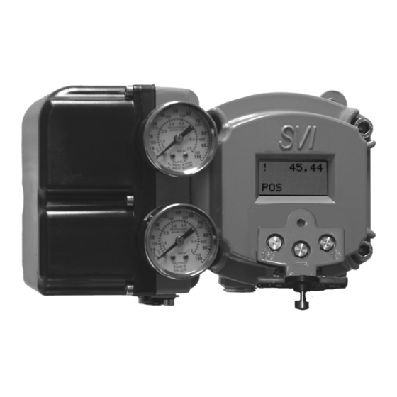
The SVI II AP is provided with Masoneilan’s ValVue software. The user-friendly interface facilitates the setup and diagnostics of a control valve. Figure 1 SVI II AP Positioner | 19 Masoneilan SVI II AP Installation and Maintenance Manual © 2017 Baker Hughes, a GE company, LLC. All rights reserved. -
Page 20: Valvue Software
Backup and restore configuration (clone device) Trend setpoint, valve position, actuator Display comparative test results (full ver- pressure sion only) Perform diagnostic test procedures (full version only) © 2017 Baker Hughes, a GE company, LLC. All rights reserved. 20 | BHGE... -
Page 21: Masoneilan Software Download
2. Use the arrows to move through the selections. Select Download below ValVue V3.30 Installer Download and Figure 3 appears. © 2017 Baker Hughes, a GE company, LLC. All rights reserved. | 21 Masoneilan SVI II AP Installation and Maintenance Manual... -
Page 22: Opening Dialog
If you are upgrading from ValVue 2.x you must update the SQL NOTE database location to match ValVue3’s. 5. Double-click on the installer and follow the instructions to install. © 2017 Baker Hughes, a GE company, LLC. All rights reserved. 22 | BHGE... -
Page 23: Opening Dialog
The dialog that appears for download varies by the program NOTE used. 3. Click Save File, click OK and it saves to the Windows Downloads folder. © 2017 Baker Hughes, a GE company, LLC. All rights reserved. | 23 Masoneilan SVI II AP Installation and Maintenance Manual... - Page 24 5. Double-click on the installer and follow the instructions to install. © 2017 Baker Hughes, a GE company, LLC. All rights reserved. 24 | BHGE...
-
Page 25: Operational Overview
Local, On-line Diagnostic Condition Monitor: Total Stem Travel, Number of Valve Cycles, Predictive Maintenance Data Advanced Valve Diagnostics with ValVue Software and the Pressure Sensor Option © 2017 Baker Hughes, a GE company, LLC. All rights reserved. | 25 Masoneilan SVI II AP Installation and Maintenance Manual... -
Page 26: Available Options
Some of the options available for the SVI II AP include: Remote Position Sensor Two Contact Outputs User Linked to Various Status and Alarm Flags Offshore Construction - Stainless Steel Housing and Components Pushbutton Display © 2017 Baker Hughes, a GE company, LLC. All rights reserved. 26 | BHGE... -
Page 27: Model And Features Comparison
Pressure: Atmospheric Pressure: Supply Pressure Sensors Pressure: I/P Pressure Pressure: Actuator P1 (Direct Port) Pressure: Actuator P2 (Reverse Port, Double-Acting) © 2017 Baker Hughes, a GE company, LLC. All rights reserved. | 27 Masoneilan SVI II AP Installation and Maintenance Manual... - Page 28 S or D S or D m = Optional and field upgrade capable using HART 1 Factory‐ordered option only. Not field upgradeable. 2 Requires ValVue Software. © 2017 Baker Hughes, a GE company, LLC. All rights reserved. 28 | BHGE...
-
Page 29: About This Manual
Indicates a potentially hazardous situation, which if not avoided WARNING could result in death or serious injury. © 2017 Baker Hughes, a GE company, LLC. All rights reserved. | 29 Masoneilan SVI II AP Installation and Maintenance Manual... -
Page 30: Bhge Documentation Resources For Masoneilan Products
Masoneilan Products SVI II AP DTM Software Manual (GEA31429) Masoneilan SVI II AP Advanced Performance Digital Positioner Bench Quick Start (GEA32138) Emerson 475 Handheld and Push Button Guide for Masoneilan SVI II AP © 2017 Baker Hughes, a GE company, LLC. All rights reserved. 30 | BHGE... -
Page 31: Installation And Set Up
SVI II AP Assembled Pneumatic Train and Cover (I/P Module Relay) Electronics Manifold Module Relay Figure 6 SVI II AP Components | 31 Masoneilan SVI II AP Installation and Maintenance Manual © 2017 Baker Hughes, a GE company, LLC. All rights reserved. -
Page 32: Svi Ii Ap High Flow Components
Manifold Cover (I/P Module) Relay Electronics Module SVI II AP Cover Figure 7 SVI II AP High Flow Components © 2017 Baker Hughes, a GE company, LLC. All rights reserved. 32 | BHGE... -
Page 33: Svi Ii Ap Dimensions And Weights
Figure 8 illustrates the dimensions and weight of the SVI II AP single-acting. Figure 8 SVI II AP Single-Acting Dimensions © 2017 Baker Hughes, a GE company, LLC. All rights reserved. | 33 Masoneilan SVI II AP Installation and Maintenance Manual... -
Page 34: Svi Ii Ap Double-Acting Dimensions
Figure 9 illustrates the dimensions and weight of the SVI II AP double-acting. Figure 9 SVI II AP Double-Acting Dimensions © 2017 Baker Hughes, a GE company, LLC. All rights reserved. 34 | BHGE... -
Page 35: Svi Ii Ap High Flow Dimensions
Figure 10 illustrates the dimensions and weight of the SVI II AP High Flow. Figure 10 SVI II AP High Flow Dimensions © 2017 Baker Hughes, a GE company, LLC. All rights reserved. | 35 Masoneilan SVI II AP Installation and Maintenance Manual... -
Page 36: Pre-Installation Issues
Connect the pneumatic tubing to the SVI II AP. See page 51 for instructions. Natural gas installation considerations. See“Installing an SVI II AP in a Natural Gas Environment” on page 167 for instruc- tions. © 2017 Baker Hughes, a GE company, LLC. All rights reserved. 36 | BHGE... -
Page 37: Installation Notes
© 2017 Baker Hughes, a GE company, LLC. All rights reserved. | 37 Masoneilan SVI II AP Installation and Maintenance Manual... -
Page 38: Before Powering Up
Tag shutoff or bypass valves to guard against a turn-on while work is in progress. Purge air from actuator and check that valve is in its unenergized position. © 2017 Baker Hughes, a GE company, LLC. All rights reserved. 38 | BHGE... -
Page 39: Filter Regulator And Tubing
SVI II AP digital valve positioner. During hydrostatic testing the shaft is thrust to its stop and a normally tightened packing retains it in that position. © 2017 Baker Hughes, a GE company, LLC. All rights reserved. | 39... -
Page 40: Camflex With Mounting Bracket (Side View)
11. Ensure that the V-Seal makes contact with the skirt around the position sensor protrusion on SVI II AP housing. Figure 11 Camflex with Mounting Bracket (Side View) © 2017 Baker Hughes, a GE company, LLC. All rights reserved. 40 | BHGE... -
Page 41: Camflex Ato Mounting (Front View)
Figure 12 Camflex ATO Mounting (Front View) Figure 13 Mounting Bracket on Air-to-Close Actuator © 2017 Baker Hughes, a GE company, LLC. All rights reserved. | 41 Masoneilan SVI II AP Installation and Maintenance Manual... -
Page 42: Travel Sensor Alignment
+8000 +/- ing setpoint 1500 (+45°) General Rule for Any amount of rota- 50% Travel 0 +/- 1000 other configu- tion Clockwise or (Mid-Stroke) rations counterclockwise (0°) © 2017 Baker Hughes, a GE company, LLC. All rights reserved. 42 | BHGE... -
Page 43: Rotary - 90
To remove the SVI II AP digital valve positioner from a rotary valve perform Steps 1 - 8 on page 36 in reverse. © 2017 Baker Hughes, a GE company, LLC. All rights reserved. | 43 Masoneilan SVI II AP Installation and Maintenance Manual... -
Page 44: Mounting The Svi Ii Ap On Reciprocating Valves
10. Thread the turnbuckle onto the left hand threaded rod end. Refer to Figure 18 on page 47. © 2017 Baker Hughes, a GE company, LLC. All rights reserved. 44 |... -
Page 45: Magnet Holder For Reciprocating Valves
Figure 15 Magnet Holder for Reciprocating Valves Figure 16 Reciprocating Valve Mounting Bracket Figure 17 Lever for Model 87/88 Multispring Actuator © 2017 Baker Hughes, a GE company, LLC. All rights reserved. | 45 Masoneilan SVI II AP Installation and Maintenance Manual... -
Page 46: Reciprocating Valve Mounting Hole And Turnbuckle Length
(12.7 - 20.32 mm) (133.35 mm) >0.8 – 1.5" 5.25" (20.32 - 38.1 mm) (133.35 mm) >1.5 – 2.5" 5.25" (38.1 - 63.5 mm) (133.35 mm) © 2017 Baker Hughes, a GE company, LLC. All rights reserved. 46 | BHGE... -
Page 47: Dismantling The Svi Ii Ap From Reciprocating Valves
To remove the SVI II AP digital valve positioner from a reciprocating valve perform Steps 1 - 12 on page 39 and page 40 in reverse. © 2017 Baker Hughes, a GE company, LLC. All rights reserved. | 47 Masoneilan SVI II AP Installation and Maintenance Manual... -
Page 48: Installing The Svi Ii Ap For Double- Acting Operation
Hole B: 1.00" to 1.50" Stroke Hole C: 2.00" to 2.50" Stroke Hole D: 3.00" to 4.50" Stroke Hole E: 5.00" to 6.00" Stroke Figure 20 Stroke Settings © 2017 Baker Hughes, a GE company, LLC. All rights reserved. 48 | BHGE... -
Page 49: Magnet Position With Valve Closed
5. Ensure the turnbuckle assembly is parallel to the stem and the magnets are in the valve closed position (Figure 22) and connect to take-off bracket. Figure 22 Magnet Position with Valve Closed © 2017 Baker Hughes, a GE company, LLC. All rights reserved. | 49 Masoneilan SVI II AP Installation and Maintenance Manual... -
Page 50: Lever Alignment
7. Mount the SVI-II with M6-1 screws. 8. Cycle the valve open to close verifying proper components movement and that rod-ends move free and clear from other components. © 2017 Baker Hughes, a GE company, LLC. All rights reserved. 50 | BHGE... -
Page 51: Connecting The Tubing And Air Supply
Particulate Matter Filtered to 5 microns Oil Content Less than 1 ppm w/w Contaminants Free of all corrosive contaminants © 2017 Baker Hughes, a GE company, LLC. All rights reserved. | 51 Masoneilan SVI II AP Installation and Maintenance Manual... -
Page 52: Single Acting Positioner
2. Connect air supply and actuator outputs (1⁄4" NPT or 1/2" NPT for High Flow units). Supply pressure is 20 -100 psi (1.4 - 6.9 bar) (138 - 690 kPa). Minimum tubing diameter 1⁄4" (6 mm x 4 mm). © 2017 Baker Hughes, a GE company, LLC. All rights reserved. 52 | BHGE... -
Page 53: Svi Ii Ap Air Ports On Single Acting Positioner
Figure 24 SVI II AP Air Ports on Single Acting Positioner Supply Output Figure 25 SVI II AP High Flow Air Ports on Single Acting Positioner © 2017 Baker Hughes, a GE company, LLC. All rights reserved. | 53 Masoneilan SVI II AP Installation and Maintenance Manual... -
Page 54: Double Acting Positioner
10.3 bar) (172 - 1030 kPa). Minimum tubing diameter 1⁄4" (6 mm x 4 mm). Output II Supply Output I Figure 26 Air Ports on Double Acting Positioner © 2017 Baker Hughes, a GE company, LLC. All rights reserved. 54 | BHGE... -
Page 55: Double Acting Positioner Ato⁄Atc Settings For Reciprocating Valves
Output 2 labeled ACT 2 connects to the opposing actuator port. Figure 27 Double Acting Positioner ATO⁄ATC Settings for Reciprocating Valves © 2017 Baker Hughes, a GE company, LLC. All rights reserved. | 55 Masoneilan SVI II AP Installation and Maintenance Manual... -
Page 56: Connecting The Air Supply
3. Connect the other end of the cable to the SVI II AP. There are two threaded openings on the positioner. Use the opening with the red plastic insert. 4. Maintain polarity + and - respectively. © 2017 Baker Hughes, a GE company, LLC. All rights reserved. 56 | BHGE... - Page 57 Wiring Considerations For a detailed description of wiring guidelines refer to “Wiring Guidelines” on page 107 of this manual. © 2017 Baker Hughes, a GE company, LLC. All rights reserved. | 57 Masoneilan SVI II AP Installation and Maintenance Manual...
- Page 58 This page intentionally left blank.
-
Page 59: Check Out And Power Up
The positioner can be moved on the valve for best drainage depending on the position of the valve in the pipeline. | 59 Masoneilan SVI II AP Installation and Maintenance Manual © 2017 Baker Hughes, a GE company, LLC. All rights reserved. -
Page 60: Check Out Procedures
Checking the Magnet There are two methods of checking the SVI II AP magnet: Perform a visual inspection Use ValVue to check the magnet © 2017 Baker Hughes, a GE company, LLC. All rights reserved. 60 | BHGE... -
Page 61: Magnet Orientation For Rotary Valves With Valve Closed
Increasing Signal = CCW Rotation ° Magnet Axis with Valve Closed Figure 29 Magnet Orientation for 90° Valve Rotation with De-energized Actuator © 2017 Baker Hughes, a GE company, LLC. All rights reserved. | 61 Masoneilan SVI II AP Installation and Maintenance Manual... -
Page 62: Magnet Holder For Reciprocating Valves
Select the installed positioner from the list of connected devices. d. Select the Raw Data tab to view the current operating conditions of the selected positioner. © 2017 Baker Hughes, a GE company, LLC. All rights reserved. 62 | BHGE... -
Page 63: Checking The Air Supply
Do not use Teflon pipe seal tape as it can shred into particles CAUTION harmful to the pneumatic components. © 2017 Baker Hughes, a GE company, LLC. All rights reserved. | 63 Masoneilan SVI II AP Installation and Maintenance Manual... -
Page 64: Checking The Electronic Module Connections
Figure 32 Connections to Electronics Module (via Terminal Board) When an SVI II AP is turned on, apply the air supply before NOTE applying the electrical input signal. © 2017 Baker Hughes, a GE company, LLC. All rights reserved. 64 | BHGE... -
Page 65: Operational Checkout
When an SVI II AP is turned on it is advisable to apply the air NOTE supply before applying the electrical input signal. © 2017 Baker Hughes, a GE company, LLC. All rights reserved. | 65 Masoneilan SVI II AP Installation and Maintenance Manual... -
Page 66: Powering Up The Svi Ii Ap
If the SVI II AP is specified without local pushbuttons and display, NOTE local operation is not available. Configure and calibrate with ® ValVue or a Hand Held HART Communicator. © 2017 Baker Hughes, a GE company, LLC. All rights reserved. 66 | BHGE... -
Page 67: Pushbutton Locks And Configuration-Lock Jumper
This is similar to Security Level 1 shown in the Pushbutton Lock Security Level table. © 2017 Baker Hughes, a GE company, LLC. All rights reserved. | 67 Masoneilan SVI II AP Installation and Maintenance Manual... - Page 68 This page intentionally left blank.
-
Page 69: Using The Digital Interfaces
Previous firmware versions reported this as TuneFail. These messages do not mean the positioner is defective but indicate a need to perform a manual tune. | 69 Masoneilan SVI II AP Installation and Maintenance Manual © 2017 Baker Hughes, a GE company, LLC. All rights reserved. -
Page 70: Local Display And Pushbuttons
The HART tool has the functionality to upload and download configurations, enter alphanumeric messages and set the custom characteristic numerical parameters. © 2017 Baker Hughes, a GE company, LLC. All rights reserved. 70 | BHGE... -
Page 71: Valvue
5. Run Auto Tune to set dynamic response. 6. Examine the device status. 7. Introduce manual set point changes to verify dynamic performance. © 2017 Baker Hughes, a GE company, LLC. All rights reserved. | 71 Masoneilan SVI II AP Installation and Maintenance Manual... -
Page 72: Pushbuttons
An exclamation point (!) in the SVI II AP display window indicates NOTE that there is instrument status available. (Select) (Forward) (Back) Figure 33 SVI II AP Display © 2017 Baker Hughes, a GE company, LLC. All rights reserved. 72 | BHGE... -
Page 73: Pushbutton Locks And Configuration-Lock Jumper
Security Level table. The following pages display the menu structure for operating the SVI II AP using local pushbuttons. © 2017 Baker Hughes, a GE company, LLC. All rights reserved. | 73 Masoneilan SVI II AP Installation and Maintenance Manual... -
Page 74: Display Menus
VIEW ERR CLR ERR SETUP DATA MAN POS <value> * - + MANUAL CALIB CONFIG CONFIG CALIB Menu Menu Figure 34 NORMAL Operation and MANUAL Menu Structures © 2017 Baker Hughes, a GE company, LLC. All rights reserved. 74 | BHGE... -
Page 75: Configure Menu
Press + or - to enter new value. Press * to accept new value and proceed QUICK50 to next menu item. CUSTOM Figure 35 CONFIGure Menu © 2017 Baker Hughes, a GE company, LLC. All rights reserved. | 75 Masoneilan SVI II AP Installation and Maintenance Manual... - Page 76 The characteristic configured in the positioner is applied in NOTE addition to the plug characteristic built into the valve trim. Do not configure a percentage characteristic if the valve has a percentage plug. © 2017 Baker Hughes, a GE company, LLC. All rights reserved. 76 | BHGE...
- Page 77 1. Press * to toggle from ENGLISH to FRANCAIS. 2. Press + to continue to scroll through Config menu. © 2017 Baker Hughes, a GE company, LLC. All rights reserved. | 77 Masoneilan SVI II AP Installation and Maintenance Manual...
-
Page 78: Guidelines For Characteristic Choice
Reciprocating valve with LINEAR TRIM Equal Percentage EQUAL50 Rotary or Reciprocating valve with EQUAL Linear Not recommended PERCENTAGE TRIM Rotary or Reciprocating valve with EQUAL Equal Percentage LINEAR PERCENTAGE TRIM © 2017 Baker Hughes, a GE company, LLC. All rights reserved. 78 | BHGE... -
Page 79: Calibration Menu
TUNE. FAILURE appears. Press * briefly and automatically return to the start of STOPS. Figure 36 CALIBration Menu © 2017 Baker Hughes, a GE company, LLC. All rights reserved. | 79 Masoneilan SVI II AP Installation and Maintenance Manual... -
Page 80: View Data Menu
VIEW DATA mode. 4. To exit from the VIEW DATA menu, press * at any menu line. You return to the last menu displayed. © 2017 Baker Hughes, a GE company, LLC. All rights reserved. 80 | BHGE... -
Page 81: View Data Menu
PRESSURE UNITS PSI, BAR, KPA TIGHT SHUTOFF T.S. ON OR T.S.OFF SIG LOW SIG HIGH Figure 37 VIEW DATA Menu © 2017 Baker Hughes, a GE company, LLC. All rights reserved. | 81 Masoneilan SVI II AP Installation and Maintenance Manual... -
Page 82: Failsafe Mode
Keep pressing to see all errors until VIEW ERR appears. Figure 38 FAILSAFE Menu © 2017 Baker Hughes, a GE company, LLC. All rights reserved. 82 | BHGE... -
Page 83: View Err Diagnostics Messages
1. Press * at CLR ERR on either the MANUAL or NORMAL mode menus. 2. Exiting from the VIEW ERR menu returns the previous menu. © 2017 Baker Hughes, a GE company, LLC. All rights reserved. | 83 Masoneilan SVI II AP Installation and Maintenance Manual... - Page 84 A standard diagnostic procedure failed to complete Warning Pneumatic / mechanical, config- uration EXT DIAG An extended diagnostic procedure failed to complete Warning Pneumatic / mechanical, config- uration © 2017 Baker Hughes, a GE company, LLC. All rights reserved. 84 | BHGE...
- Page 85 >120 psi (8.28 bar, 828 kPa) PRES5 ER Temperature compensated pressure sensor 5 reading is Warning outside the range © 2017 Baker Hughes, a GE company, LLC. All rights reserved. | 85 Masoneilan SVI II AP Installation and Maintenance Manual...
-
Page 86: Display And Clear Error Messages
* to return to NORMAL operating mode, if NORMAL appears. * to return to MANUAL Mode menu, if MANUAL appears. 3. Press + repeatedly until -› NORMAL appears. © 2017 Baker Hughes, a GE company, LLC. All rights reserved. 86 | BHGE... -
Page 87: Hand Held Communicator
Do not operate a PC in a hazardous area without compliance to local and plant regulations. © 2017 Baker Hughes, a GE company, LLC. All rights reserved. | 87 Masoneilan SVI II AP Installation and Maintenance Manual... -
Page 88: Hart® 6 And 7 Squawk Command
LCD display Squawk for two seconds. Squawk displayed Non-squawked display ® HART Command 72 (Squawk) from ValVue SVI II AP DTM (red box) ® Figure 39 HART Command 72 Squawk Function © 2017 Baker Hughes, a GE company, LLC. All rights reserved. 88 | BHGE... -
Page 89: Configuration And Calibration Using Pushbuttons
Autotune procedure. Alternately, Try starting tuning from the 50% position. | 89 Masoneilan SVI II AP Installation and Maintenance Manual © 2017 Baker Hughes, a GE company, LLC. All rights reserved. -
Page 90: Rough Guide To Effect S Of Changing Pid Values
Increase I term by 20-25% Add Dead Zone – try 0.25% Valve moves too slowly: P term too low, try increasing by 25% Stroking time set to non-zero value. © 2017 Baker Hughes, a GE company, LLC. All rights reserved. 90 | BHGE... -
Page 91: Configuration With Pushbutton Display
16. Return to NORMAL mode. The valve moves to the Value set by the current calibrator. 17. Stroke the valve through its range to verify that the movement is as desired. © 2017 Baker Hughes, a GE company, LLC. All rights reserved. | 91... -
Page 92: View Data Settings
EQ% 50:1 EQ% CAMFX QUICK 50 CUSTOM 0.00 2.00 TS OFF TS ON 4.00 4.00 SIG LO SIG LO 20.00 12.00 SIG HI SIG HI ENGLISH FRENCH © 2017 Baker Hughes, a GE company, LLC. All rights reserved. 92 | BHGE... -
Page 93: Configuration Pushbutton Guide
Press * to accept new value and proceed QUICK50 to next menu item. CUSTOM Figure 40 Configuration Pushbutton Guide © 2017 Baker Hughes, a GE company, LLC. All rights reserved. | 93 Masoneilan SVI II AP Installation and Maintenance Manual... -
Page 94: Calibration
9. Observe all warnings. 10. Press * and the valve strokes and automatically calibrates valve travel. 11. After the STOPS procedure finishes, press + twice until TUNE appears. © 2017 Baker Hughes, a GE company, LLC. All rights reserved. 94 | BHGE... -
Page 95: Correct For Over Travel
4. Use the + and - buttons to position the valve to the nominal full open position. 5. Press * to accept this position as the new 100% position. © 2017 Baker Hughes, a GE company, LLC. All rights reserved. | 95... -
Page 96: Adjust Input Signal Range
Adjustment is normally required only for split range applications and provides flexibility for unusual applications. A separate ValVue calibration procedure enables adjustment of the current sensing circuit to a precision current reference standard. © 2017 Baker Hughes, a GE company, LLC. All rights reserved. 96 | BHGE... -
Page 97: Calibration Pushbutton Guide
TUNE. FAILURE displays. Press * briefly and automatically return to the start of STOPS. Figure 41 Calibration Pushbutton Guide © 2017 Baker Hughes, a GE company, LLC. All rights reserved. | 97 Masoneilan SVI II AP Installation and Maintenance Manual... -
Page 98: Check-Out With A Hart® Handheld Communicator
For example, the following message is displayed if the instrument has been serviced and the air is not connected. “ Process applied to the non-primary variable is outside the operating limits of the field device” © 2017 Baker Hughes, a GE company, LLC. All rights reserved. 98 | BHGE... - Page 99 14. Correct the problem (Is the air supply on?), and then go to clear status until Clear Fault codes Completed appears. 15. Press OK. © 2017 Baker Hughes, a GE company, LLC. All rights reserved. | 99 Masoneilan SVI II AP Installation and Maintenance Manual...
-
Page 100: Emerson 475 Handheld Menu Structure And Procedures
Emerson 475 Handheld Menu Structure The menu structure shown below starts in the upper left hand corner of the card (Firmware ® ® 3.2.3 HART 5 , 4.1.1 (HART © 2017 Baker Hughes, a GE company, LLC. All rights reserved. 100 | BHGE... -
Page 101: Run Auto Tune
2. Tap Status/Diagnostics. 3. Tap Signature. 4. Tap Run Diagnostics. You are led through a series of screens run the process. © 2017 Baker Hughes, a GE company, LLC. All rights reserved. | 101 Masoneilan SVI II AP Installation and Maintenance Manual... -
Page 102: View And Clear Faults
Historical Faults to view all faults current and past. Clear All Faults to clear current and historical faults. 4. Tap Fault List to view the full fault code list. © 2017 Baker Hughes, a GE company, LLC. All rights reserved. 102 | BHGE... -
Page 103: Configuring And Calibrating With Valvue
Install the cover and tighten all four screws. There must be no gap between the housing and cover. © 2017 Baker Hughes, a GE company, LLC. All rights reserved. | 103 Masoneilan SVI II AP Installation and Maintenance Manual... - Page 104 This page intentionally left blank.
-
Page 105: Wiring An Svi Ii Ap
It will suffice to explain the requirements as a guide use to obtain necessary components from many sources for a successful installation. | 105 Masoneilan SVI II AP Installation and Maintenance Manual © 2017 Baker Hughes, a GE company, LLC. All rights reserved. - Page 106 Before carrying out any work on the device, power off the instrument or make sure that the locale conditions for potentially explosive atmosphere permit the safe opening of the cover. © 2017 Baker Hughes, a GE company, LLC. All rights reserved. 106 | BHGE...
-
Page 107: Wiring Guidelines
Ensure that the position retransmit signal is connected to the control system’s analog input card. Ensure the control loop is powered while making make measurements with a meter. © 2017 Baker Hughes, a GE company, LLC. All rights reserved. | 107 Masoneilan SVI II AP Installation and Maintenance Manual... -
Page 108: Svi Ii Ap Setups
(+) terminal and the negative lead to the negative (-) terminal. Reversal of input will not cause damage but the unit will not function. © 2017 Baker Hughes, a GE company, LLC. All rights reserved. 108 |... -
Page 109: General Purpose And Explosion Proof Installation
220 Ohms HART compliant control system output card HART Modem ValVue DPI620 Figure 43 General Purpose and Explosion Proof Installation © 2017 Baker Hughes, a GE company, LLC. All rights reserved. | 109 Masoneilan SVI II AP Installation and Maintenance Manual... -
Page 110: Intrinsically Safe Installation
SVI II AP Zener Barrier Barrier Power Resistance Supply 220 Ohms HART Compliant Control System Output Card GE DPI620 HART Modem ValVue Figure 44 Intrinsically Safe Installation © 2017 Baker Hughes, a GE company, LLC. All rights reserved. 110 | BHGE... -
Page 111: Grounding Practices
Conclusion: The control system must have a compliance voltage equal to or greater than 17.64 V; contact the DCS vendor to verify compliance. © 2017 Baker Hughes, a GE company, LLC. All rights reserved. | 111 Masoneilan SVI II AP Installation and Maintenance Manual... -
Page 112: Wire Size And Conduit
When an intrinsic safety barrier separates the SVI II AP from the NOTE ® modem or handheld a HART compliant barrier must be used. © 2017 Baker Hughes, a GE company, LLC. All rights reserved. 112 | BHGE... -
Page 113: Hart® Physical Layer Compliance Of The Control System
© 2017 Baker Hughes, a GE company, LLC. All rights reserved. | 113 Masoneilan SVI II AP Installation and Maintenance Manual... -
Page 114: Cabling And Interconnection Requirements
HART filter NOTE installed. Contact the manufacturer of the controller or DCS. See “HART® Filter Requirements” on page 125. of this manual for more information. © 2017 Baker Hughes, a GE company, LLC. All rights reserved. 114 | BHGE... -
Page 115: Split Range Applications
Grounding the case is unnecessary for functional purposes. Grounding the case may be necessary to conform to local codes. © 2017 Baker Hughes, a GE company, LLC. All rights reserved. | 115 Masoneilan SVI II AP Installation and Maintenance Manual... -
Page 116: Multiple Output Circuit Control System
® For more information on this and how to setup Field Networks, including setting up for HART and FF communications, see the ValVue help Field Networks. © 2017 Baker Hughes, a GE company, LLC. All rights reserved. 116 | BHGE... -
Page 117: Isolators
Do not use 0 for any of the positioners. A 0 causes ® HART masters to stop searching for additional positioners. © 2017 Baker Hughes, a GE company, LLC. All rights reserved. | 117 Masoneilan SVI II AP Installation and Maintenance Manual... -
Page 118: Split Range With Isolator
HART Address = 1 Isolator HART Filter Control System Output Card HART Modem ValVue HART Address = 2 I.S. Galvanic Isolator Figure 46 Split Range with Isolator © 2017 Baker Hughes, a GE company, LLC. All rights reserved. 118 | BHGE... -
Page 119: Supplemental Power Supply
20 mA to SVI II AP input. If 20 mA is not attainable, troubleshoot the source and set up. © 2017 Baker Hughes, a GE company, LLC. All rights reserved. | 119 Masoneilan SVI II AP Installation and Maintenance Manual... -
Page 120: Split Range With Supplemental Power Supply - Non-Hazardous
Supplemental (Voltage) HART Control Power Filter Supply System Output Card HART Modem HART Address = 2 Figure 47 Split Range with Supplemental Power Supply - Non-Hazardous © 2017 Baker Hughes, a GE company, LLC. All rights reserved. 120 | BHGE... -
Page 121: Required Practices For Explosion Proof Installations
© 2017 Baker Hughes, a GE company, LLC. All rights reserved. | 121 Masoneilan SVI II AP Installation and Maintenance Manual... - Page 122 This page intentionally left blank.
-
Page 123: Hart® Communications With Intrinsic Safety
To determine if the installation will perform successfully with HART communications you must ® ® consider HART filter requirements and HART barrier compliance. | 123 Masoneilan SVI II AP Installation and Maintenance Manual © 2017 Baker Hughes, a GE company, LLC. All rights reserved. -
Page 124: Hart® Barrier Compliance
Consult the manufacturer or refer to the documents listed at the end of this instruction manual. ® Figure 48 Intrinsically Safe Installation with Zener Barrier and HART Filter © 2017 Baker Hughes, a GE company, LLC. All rights reserved. 124 | BHGE... -
Page 125: Output Channel Isolation
® If a HART filter is required, then its voltage drop must be considered in calculating the compliance voltage. © 2017 Baker Hughes, a GE company, LLC. All rights reserved. | 125 Masoneilan SVI II AP Installation and Maintenance Manual... -
Page 126: Intrinsically Safe Installation With Galvanic Isolator
HART filter NOTE installed. Contact the manufacturer of the controller or DCS. See ® HART Filter Required for Certain Controls System Output Circuits. © 2017 Baker Hughes, a GE company, LLC. All rights reserved. 126 | BHGE... -
Page 127: Modem And Computer Use In Intrinsically Safe Circuits
Observe the labels on the handheld communicator or consult the manufacturer. © 2017 Baker Hughes, a GE company, LLC. All rights reserved. | 127 Masoneilan SVI II AP Installation and Maintenance Manual... - Page 128 This page intentionally left blank.
-
Page 129: Operation And Maintenance
Input Current 4 to 20 mA Figure 50 Block Diagram with I/P Converter and Pressure Sensor | 129 Masoneilan SVI II AP Installation and Maintenance Manual © 2017 Baker Hughes, a GE company, LLC. All rights reserved. -
Page 130: Physical And Operational Description
The pressure sensor located in the Electronics Module measures the output of the single ® acting relay. The pressure measurement is displayed on the local display or read by a HART communication device. © 2017 Baker Hughes, a GE company, LLC. All rights reserved. 130 | BHGE... -
Page 131: Output Switches
(the digital switch is in the open state). Under open circuit conditions, the switch current will be less than 0.200 mA. © 2017 Baker Hughes, a GE company, LLC. All rights reserved. | 131 Masoneilan SVI II AP Installation and Maintenance Manual... -
Page 132: Switch Installation Drawing: Correct Configuration With Load
External SVI II AP (no current limit in NOT ALLOWED Voltage Switch place) Source Output Figure 52 Switch Installation Drawing without Load: Configuration Not Allowed © 2017 Baker Hughes, a GE company, LLC. All rights reserved. 132 | BHGE... - Page 133 The contacts are OPEN when the SVI II AP is unpowered and may NOTE be made to be open or closed when the flag is asserted after boot. © 2017 Baker Hughes, a GE company, LLC. All rights reserved. | 133 Masoneilan SVI II AP Installation and Maintenance Manual...
-
Page 134: Pneumatic Module
100 psi (6.9 bar, 690 kPa). I/P Current to Pneumatic Converter Relay (Pneumatic Amplifier) Vent Figure 53 SVI II AP Pneumatic Module with Single Acting Relay © 2017 Baker Hughes, a GE company, LLC. All rights reserved. 134 | BHGE... -
Page 135: Svi Ii Ap High Flow Pneumatic Module With Single Acting Relay
I/P Current to Pneumatic Converter Relay (Pneumatic Amplifier) Vent Figure 54 SVI II AP High Flow Pneumatic Module with Single Acting Relay © 2017 Baker Hughes, a GE company, LLC. All rights reserved. | 135 Masoneilan SVI II AP Installation and Maintenance Manual... -
Page 136: Double Acting Pneumatic Relay
Do not exceed the maximum pressure rating of the actuator. The double acting relay is adjusted at the factory and set to 70% of supply pressure. If adjustment is required consult the factory. © 2017 Baker Hughes, a GE company, LLC. All rights reserved. 136 | BHGE... -
Page 137: Svi Ii Ap D/A Bleed Slots
Figure 57 relates the red box callouts in Figure 56 to a complete unit. Figure 56 Bleed Slots On Air Routing Plate Figure 57 Bleed Slots on Complete Unit © 2017 Baker Hughes, a GE company, LLC. All rights reserved. | 137 Masoneilan SVI II AP Installation and Maintenance Manual... -
Page 138: Optional Display And Pushbuttons
Only parts supplied by the factory are permitted. This includes not only the major assemblies but also mounting screws and O-rings. No substitutions with non-Masoneilan parts are permitted. © 2017 Baker Hughes, a GE company, LLC. All rights reserved. 138 | BHGE... -
Page 139: Tools Needed
2. Lift the cover off the positioner. Display Cover Pneumatic Cover Figure 58 SVI II AP Display and Pneumatic Covers © 2017 Baker Hughes, a GE company, LLC. All rights reserved. | 139 Masoneilan SVI II AP Installation and Maintenance Manual... - Page 140 No wires or retaining cable can be trapped under the cover flange. The flange area is not corroded and the surface is not scarred. The four cover bolts are securely tightened to 50 in-lbs (5.65 N-m). © 2017 Baker Hughes, a GE company, LLC. All rights reserved. 140 | BHGE...
-
Page 141: I⁄P Module Removal And Installation
1. Using a 3 mm hex key, remove the four screws from around the perimeter of the cover (Figure 59 or Figure 60). Figure 59 Pneumatic Cover Screws: High Flow © 2017 Baker Hughes, a GE company, LLC. All rights reserved. | 141 Masoneilan SVI II AP Installation and Maintenance Manual... -
Page 142: Pneumatic Cover Screws: Ap (Four Shown)
2. Using a 3 mm hex key, remove the four screws from around the perimeter of the I⁄P module. Figure 61 SVI II AP High Flow Pneumatic Module with Single Acting Relay 3. Lift the module off the positioner. © 2017 Baker Hughes, a GE company, LLC. All rights reserved. 142 | BHGE... -
Page 143: Relay Removal And Installation
When you have completed maintenance on the pneumatic relay it NOTE is necessary to reinstall the pneumatic cover. Refer to on “Pneumatic Cover Installation” on page 143. © 2017 Baker Hughes, a GE company, LLC. All rights reserved. | 143 Masoneilan SVI II AP Installation and Maintenance Manual... -
Page 144: Adjusting I/P Zero
Run STOPS, and autoTUNE, and the repair is complete. The positioner that was removed can be refurbished and reused. Substitution of components can void safety approvals. NOTE © 2017 Baker Hughes, a GE company, LLC. All rights reserved. 144 | BHGE... -
Page 145: Internal Diagnostics
© 2017 Baker Hughes, a GE company, LLC. All rights reserved. | 145 Masoneilan SVI II AP Installation and Maintenance Manual... -
Page 146: Upgrading Firmware
5 (3.2.7) and HART 7 (5.1.3) capable Tools Required ® HART modem ® PC/laptop with Windows 7 or later, 4 GB RAM SMARTs Assistant Ver. 3.x © 2017 Baker Hughes, a GE company, LLC. All rights reserved. 146 | BHGE... -
Page 147: Installing Firmware Upgrade
“Installation and Set Up” on page 31. Consult the factory for firmware upgrade services. ValVue is the recommended tool for complete re-configuration. See “Configuration and Calibration Using Pushbuttons” on page 89. © 2017 Baker Hughes, a GE company, LLC. All rights reserved. | 147 Masoneilan SVI II AP Installation and Maintenance Manual... - Page 148 This page intentionally left blank.
-
Page 149: 10. Specifications And References
1 G at 150 - 2000 Hz - Less than 2% of span Magnetic Field Influence Negligible at 30 A/m (EN61000-4-8) CE MARK certified to EN50081-2 and EN50082-2 | 149 Masoneilan SVI II AP Installation and Maintenance Manual © 2017 Baker Hughes, a GE company, LLC. All rights reserved. -
Page 150: Operational Specifications
SV = Actuator Pressure (P1-P2) (N/A for standard diagnostic version; units sends zero) TV = Supply Pressure QV = P2 for double acting units (N/A for standard diagnostic version; units sends zero) © 2017 Baker Hughes, a GE company, LLC. All rights reserved. 150 | BHGE... -
Page 151: Input Signal, Power, And Display Specifications
300 series stainless steel Magnet Holder Corrosion Protected Anodized Aluminum 6061 T6 Pole Ring 416 stainless steel Levers 300 Series stainless steel © 2017 Baker Hughes, a GE company, LLC. All rights reserved. | 151 Masoneilan SVI II AP Installation and Maintenance Manual... -
Page 152: System Connectivity
Loss of Input Signal Output drops to low pressure. Output Pressure 0-150 psi (10.3 bar) max Sweet Natural Gas S content not more than 20 ppm © 2017 Baker Hughes, a GE company, LLC. All rights reserved. 152 | BHGE... -
Page 153: High Flow Pneumatics Single Acting High Flow
0.4 scf/min. (11.3 L/min.) at 30 psi (2.1 bar) supply Double Acting 0.85 scf/min. (22.6 L/min.) at 80 psi (5.52 bar) supply © 2017 Baker Hughes, a GE company, LLC. All rights reserved. | 153 Masoneilan SVI II AP Installation and Maintenance Manual... - Page 154 ® ® device in HART 5 (3.2.5) or HART 7 (5.1.1). Similarly, firmware 3.2.3/4.1.1 can operate in ® ® HART 5 (3.2.3) or HART 6 (4.1.1). © 2017 Baker Hughes, a GE company, LLC. All rights reserved. 154 | BHGE...
-
Page 155: Device Variables
Current to pressure transducer current Available for firm- ware 5.1.X (in ® HART 7 only). " Friction Static valve friction © 2017 Baker Hughes, a GE company, LLC. All rights reserved. | 155 Masoneilan SVI II AP Installation and Maintenance Manual... - Page 156 Open Stop Upper limit for valve travel Percent " Adjustment Percent of Range Analog Input current signal in percentage Percent " © 2017 Baker Hughes, a GE company, LLC. All rights reserved. 156 | BHGE...
-
Page 157: Svi Ii Ap Model Numbering
1. ATEX/FM/CSA/Intrinsic Safety and Exprf 4. ATEX (IS, NI) Approved Configuration Codes SVI2 AP- Figure 63 SVI II AP Model Numbering © 2017 Baker Hughes, a GE company, LLC. All rights reserved. | 157 Masoneilan SVI II AP Installation and Maintenance Manual... -
Page 158: Spare Parts
Spare Parts © 2017 Baker Hughes, a GE company, LLC. All rights reserved. 158 | BHGE... - Page 159 © 2017 Baker Hughes, a GE company, LLC. All rights reserved. | 159 Masoneilan SVI II AP Installation and Maintenance Manual...
- Page 160 © 2017 Baker Hughes, a GE company, LLC. All rights reserved. 160 | BHGE...
- Page 161 1.78 [0.0703] REF NO 2-025 720020224-681-0000 O-RING ID 9.137.82 [1.498] WIDTH 1.78 [0.0703] REF NO 2-029 720014540-779-0000 Instructions 720009638-999-0000 RELAY SA HCR © 2017 Baker Hughes, a GE company, LLC. All rights reserved. | 161 Masoneilan SVI II AP Installation and Maintenance Manual...
- Page 162 This page intentionally left blank.
-
Page 163: 11. Air To Open And Air To Close Actuators
3.6 mA, below which the positioner is initializing its settings until power is stabilized. | 163 Masoneilan SVI II AP Installation and Maintenance Manual © 2017 Baker Hughes, a GE company, LLC. All rights reserved. -
Page 164: Ato And Atc Action With Linear Positioner Characteristics
Figure 64 ATO and ATC Action with Linear Positioner Characteristics © 2017 Baker Hughes, a GE company, LLC. All rights reserved. 164 | BHGE... -
Page 165: Ato And Atc Action In Percentage Of Positioner Characteristics
Figure 65 ATO and ATC Action in Percentage of Positioner Characteristics © 2017 Baker Hughes, a GE company, LLC. All rights reserved. | 165 Masoneilan SVI II AP Installation and Maintenance Manual... - Page 166 This page intentionally left blank.
-
Page 167: 12. Installing An Svi Ii Ap In A Natural Gas Environment
WARNING: EXPLOSION HAZARD- An improperly installed cover or pressure containing component could leak natural gas into the SVI II AP install area. | 167 Masoneilan SVI II AP Installation and Maintenance Manual © 2017 Baker Hughes, a GE company, LLC. All rights reserved. - Page 168 /min @ 30 psi (6 sLp/min) of natural gas exhausts from the I/P and is vented. For indoor applications, take this into consideration and provide circulation and venting. The exhaust points are shown below using red arrows ( Double Acting Single Acting High Flow © 2017 Baker Hughes, a GE company, LLC. All rights reserved. 168 | BHGE...
-
Page 169: Remote Actuator Vent Gas Connection
M3 and M5 Hex Key Use an M3 hex key to remove the exhaust cover. Figure 66 Step 1 Remove the Exhaust Cover © 2017 Baker Hughes, a GE company, LLC. All rights reserved. | 169 Masoneilan SVI II AP Installation and Maintenance Manual... - Page 170 6. Ensure the covers and other pressure containing components are correctly installed before putting the unit into service. Figure 68 Step 4 Connect Gas Supply and Exhaust © 2017 Baker Hughes, a GE company, LLC. All rights reserved. 170 | BHGE...
-
Page 171: High Flow Installation
6. Ensure the covers and other pressure containing components are correctly installed before putting the unit into service. Figure 70 Step 2 Connect Gas Supply and Exhaust © 2017 Baker Hughes, a GE company, LLC. All rights reserved. | 171 Masoneilan SVI II AP Installation and Maintenance Manual... - Page 172 This page intentionally left blank.
-
Page 173: 13. Air Supply Requirements
| 173 Masoneilan SVI II AP Installation and Maintenance Manual © 2017 Baker Hughes, a GE company, LLC. All rights reserved. - Page 174 This page intentionally left blank.
-
Page 175: 14. Adjusting Speed Of Response
You can adjust the speed of response of the control valve by adjusting parameters in SVI II AP. Tuning parameters are adjusted by ValVue, the preferred method, or by the handheld. | 175 Masoneilan SVI II AP Installation and Maintenance Manual © 2017 Baker Hughes, a GE company, LLC. All rights reserved. - Page 176 This page intentionally left blank.
-
Page 177: 15. Advanced Usage
See recommended Tight Shutoff settings in the following table. Tight shutoff ® can be adjusted with pushbuttons or with ValVue or a HART communicator. | 177 Masoneilan SVI II AP Installation and Maintenance Manual © 2017 Baker Hughes, a GE company, LLC. All rights reserved. -
Page 178: Using Valvue Diagnostics
ValVue to specify the criterion for time-spent-near-closed (a valve position such as 4%, for example). See also Tight shutoff- Application to High Pressure Liquid Letdown Valve Trim. © 2017 Baker Hughes, a GE company, LLC. All rights reserved. 178 |... -
Page 179: Diagnostic Valve Tests
The full version of ValVue is required for diagnostic tests. © 2017 Baker Hughes, a GE company, LLC. All rights reserved. | 179 Masoneilan SVI II AP Installation and Maintenance Manual... - Page 180 This page intentionally left blank.
-
Page 181: 16. Glossary
Closed The valve position in which the flow is minimum or zero. See Tight Shutoff. | 181 Masoneilan SVI II AP Installation and Maintenance Manual © 2017 Baker Hughes, a GE company, LLC. All rights reserved. - Page 182 Often system performance signatures are obtained and retained to compare as-built with future perfor- mance to predict remaining useful service life. © 2017 Baker Hughes, a GE company, LLC. All rights reserved. 182 | BHGE...
- Page 183 Frequency Shift Keying see HART protocol. Hall Effect Sensor A semiconductor magnetic-field sensor that measures the magnetic flux perpendicular to the sensor. © 2017 Baker Hughes, a GE company, LLC. All rights reserved. | 183 Masoneilan SVI II AP Installation and Maintenance Manual...
- Page 184 The current to pressure converting device. The SVI II AP sends an analog current signal to the I⁄P which produces a controlled pressure to the pneumatic amplifying relay. © 2017 Baker Hughes, a GE company, LLC. All rights reserved. 184 | BHGE...
- Page 185 SVI II AP can be configured to provide the same limits through software control of position. © 2017 Baker Hughes, a GE company, LLC. All rights reserved. | 185 Masoneilan SVI II AP Installation and Maintenance Manual...
- Page 186 The component that amplifies the pneumatic control signals to pro- vide a wide range of actuation pressure and to supply and vent at high flow rates for responsive control. © 2017 Baker Hughes, a GE company, LLC. All rights reserved. 186 | BHGE...
- Page 187 VIEW ERR A mode of the positioner in which the error status or error messages can be examined. © 2017 Baker Hughes, a GE company, LLC. All rights reserved. | 187 Masoneilan SVI II AP Installation and Maintenance Manual...
- Page 188 This page intentionally left blank.
-
Page 189: 17. Burst Mode Operations
Choose the Burst command variables to be returned by referring to list of device variables in Table 28 on page 155. Figure 71 Burst Mode Configuration | 189 Masoneilan SVI II AP Installation and Maintenance Manual © 2017 Baker Hughes, a GE company, LLC. All rights reserved. - Page 190 This page intentionally left blank.
-
Page 191: 18. Device Status Diagnostics
15 psig (dou- + 10 psig. ble acting). 2. Double Acting: Increase air supply above 15-20 psig. | 191 Masoneilan SVI II AP Installation and Maintenance Manual © 2017 Baker Hughes, a GE company, LLC. All rights reserved. - Page 192 2. Timeout occurred due to large actuator with insufficient boosters. 3. Valve position could not stabi- lize when de-energizing or when energizing the actuator. © 2017 Baker Hughes, a GE company, LLC. All rights reserved. 192 | BHGE...
- Page 193 2. Check for blockage of valve, hand wheel, etc. 3. Check for linkage problems. 4. Check for air leakage in the positioner actuator system. © 2017 Baker Hughes, a GE company, LLC. All rights reserved. | 193 Masoneilan SVI II AP Installation and Maintenance Manual...
- Page 194 2. Clear the alarm using ValVue or HART ® Host. 3. If the failure persists, replace the complete device or electron- ics module. © 2017 Baker Hughes, a GE company, LLC. All rights reserved. 194 | BHGE...
- Page 195 0 and 1.25 V. 4. If correct sensor selected, replace electronics module and report the problem at svisup- port@bhge.com. © 2017 Baker Hughes, a GE company, LLC. All rights reserved. | 195 Masoneilan SVI II AP Installation and Maintenance Manual...
- Page 196 2. Clear the alarm using ValVue or HART ® Host. 3. If the failure persists, replace the complete device or electron- ics module. © 2017 Baker Hughes, a GE company, LLC. All rights reserved. 196 | BHGE...
- Page 197 2. Clear the alarm using ValVue or HART ® Host. 3. If the failure persists, replace the complete device or electron- ics module. © 2017 Baker Hughes, a GE company, LLC. All rights reserved. | 197 Masoneilan SVI II AP Installation and Maintenance Manual...
- Page 198 2. Clear the alarm using ValVue ® or HART Host. 3. If the failure persists, replace the complete device or electron- ics module. © 2017 Baker Hughes, a GE company, LLC. All rights reserved. 198 | BHGE...
-
Page 199: Determining An Svi Positioner Compliance Voltage In A Control System
20 VDC, which is a sufficient maximum. Compliance Test Setup 1. Configure a test setup as in Figure 72. Figure 72 Compliance Voltage Test Setup | 199 Masoneilan SVI II AP Installation and Maintenance Manual © 2017 Baker Hughes, a GE company, LLC. All rights reserved. -
Page 200: Expected Voltage Range At Positioner Terminals
9.5 to 10.5 V 12 mA 10 V 9 to 10 V 16 mA 9.5 V 8.5 to 9.5 V 20 mA 8 to 9 V © 2017 Baker Hughes, a GE company, LLC. All rights reserved. 200 | BHGE... -
Page 201: 20. How Do I Interface With The Svi Ii Ap Dtm
Trend dis- play. Installing SVI II AP Advanced DTM Software. Calibration Calibration Screen: to calibrate pressure and input signals. | 201 Masoneilan SVI II AP Installation and Maintenance Manual © 2017 Baker Hughes, a GE company, LLC. All rights reserved. - Page 202 I/Os. Additionally, you can set the I/O Output. Diagnostics Health Screen: to view the status of signals, pressure, temperatures and I/Os. © 2017 Baker Hughes, a GE company, LLC. All rights reserved. 202 | BHGE...
- Page 204 © 2017 Baker Hughes, a GE company, LLC. - All rights reserved. Baker Hughes, a GE company, LLC and its affiliates (“BHGE”) provides this information on an “as is” basis for general information purposes and believes it to be accurate as of the date of publication. BHGE does...
Need help?
Do you have a question about the Masoneilan SVIII AP and is the answer not in the manual?
Questions and answers