Table of Contents
Advertisement
Quick Links
Advertisement
Table of Contents

Related Manuals for THORLABS MPZ601


Summary of Contents for THORLABS MPZ601
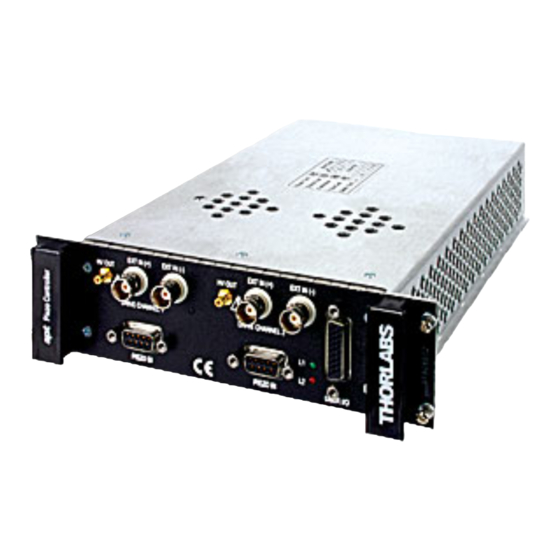
- Page 1 PIEZOELECTRIC CONTROL MODULE Model Number MPZ601...
- Page 2 THORLABS About the Company Thorlabs has been an active member of the Photonics community for over 15 years. We strive to be the ultimate resource for the photonics community-a place to find the products you need to enable your experiments, as well as the information you need to get your application working.
-
Page 3: Table Of Contents
Contents 1 For Your Safety ..................3 Safety Information ......................3 Warnings ........................4 Declarations Of Conformity .................... 4 For Customers in Europe ..................4 For Customers In The USA ..................4 Waste Electrical and Electronic Equipment (WEEE) Directive ........5 Compliance ...................... - Page 4 4 Operation ....................19 Manual Operation ......................19 Operation From The GUI Panel ................19 Piezo Controller Settings Panel ................22 Setting the Position Sensor Zero ................. 24 Choice of Display Mode ..................24 Detection of Range of Travel ................24 5 Installation and Maintenance ..............
-
Page 5: For Your Safety
Chapter 1 For Your Safety 1.1 Safety Information For the continuing safety of the operators of this equipment, and the protection of the equipment itself, the operator should take note of the Warnings, Cautions and Notes throughout this handbook and, where visible, on the product itself. The following safety symbols may be used on the equipment: Warning, risk of danger. -
Page 6: Warnings
Operation of this equipment in a residential area is likely to cause harmful interference in which case the user will be required to correct the interference at his own expense. Changes or modifications not expressly approved by Thorlabs Ltd could void the user’s authority to operate the equipment. -
Page 7: Waste Electrical And Electronic Equipment (Weee) Directive
Fig. 1.1 Crossed out "wheelie bin" symbol As the WEEE directive applies to self contained operational electrical and electronic products, this "end of life" take back service does not refer to other Thorlabs products, such as •... -
Page 8: Waste Treatment On Your Own Responsibility
1.4.2 Waste treatment on your own responsibility If you do not return an "end of life" unit to Thorlabs, you must hand it to a company specialized in waste recovery. Do not dispose of the unit in a litter bin or at a public waste disposal site. -
Page 9: Overview
2.1 APT Rack System Description 2.1.1 Introduction Thorlabs has an extensive range of one-, two- and three-axis controllers for stepper motor and piezo actuator control. Increasingly, production of optoelectronic components requires fully automated or semiautomated control of a large number of mechanical stages. -
Page 10: Ease Of Use
Overview 2.1.3 Ease of Use The rack system architecture, hardware and software has been skilfully engineered to provide an efficient and effective solution to complex high channel count applications. The APT rack presents a clean, uncluttered front panel, with six rear mounting bays for the plug-in modules. -
Page 11: Software
Typically, such positioning sequences require a series of descrete movements and measurements to implement an overall solution The mechanical stage options and drive electronics offered by Thorlabs are ideally suited to performing all of these individual steps in a variety of different ways. - Page 12 Overview Consider the ActiveX Control supplied for the APT Piezo control module. This Control provides a complete user graphical instrument panel to allow the Piezo unit to be manually operated, as well as a complete set of software functions (often called methods) to allow all parameters to be set and Piezo control operations to be automated by a client application.
-
Page 13: Apt User.exe
MPZ601 Piezoelectric Control Module 2.2.3 APT User.exe The APTUser application allows the user to interact with a number of APT hardware control units connected to the host PC. This program displays multiple graphical instrument panels to allow multiple APT units to be controlled simultaneously. -
Page 14: Apt Config Utility
Overview 2.2.4 APT Config Utility There are many system parameters and configuration settings associated with the operation of the APT Server (ActiveX Controls). Most can be directly accessed using the various graphical panels and their associated programmable interfaces. However there are several system wide settings that can be made 'off-line' before running the APT software. -
Page 15: Piezo Controller Description
2.3 Piezo Controller Description 2.3.1 Introduction The APT Modular Piezoelectric Controller is a component of the Thorlabs APT Modular Motion Control System, and is designed to be fully integrated into larger systems that also contain our stepper motor drive and NanoTrak™ modules. It... -
Page 16: Open Architecture
Overview 2.3.4 Open Architecture A key benefit of the APT rack system's architecture is that the user interface software is able to unify the operation of a large number of modules, each performing its own set of functions in a true object-oriented fashion. By carefully ensuring compatibility in embedded design, the APT Piezo module is seamlessly supported by the same highly functional multithreaded ActiveX software suite developed for the bench top controllers. -
Page 17: Rear Panel Connections
MPZ601 Piezoelectric Control Module 2.4 Rear Panel Connections EXT IN (+) EXT IN (-) EXT IN (+) EXT IN (-) HV OUT HV OUT Model No. DRIVE CHANNEL 1 DRIVE CHANNEL 2 MPZ601 PIEZO IN PIEZO IN USER I/O Fig. 2.1 Rear panel connections DRIVE CHANNEL 1 HV OUT (SMC connector) –... -
Page 18: Principles Of Operation
– see Fig. 3.1. In this way, the distance from positive to negative electrodes is very small. A large field gradient can therefore be obtained with a modest drive voltage (75 V in the case of Thorlabs actuators). expansion piezoelectric... -
Page 19: Hysteresis
Some Thorlabs nanopositioning actuators have position sensing, others do not. The Piezoelectric control module allows both types to be controlled. - Page 20 Principles of Operation Open loop control moving part demand actuator Closed loop control moving part demand actuator a + b/s – sensor Fig. 3.3 Open loop and closed loop control The result of using closed-loop control is a linear relationship between demand (voltage) and measured position –...
-
Page 21: Operation
Chapter 4 Operation 4.1 Manual Operation 4.1.1 Operation From The GUI Panel Fig. 4.1 Piezo Controller GUI panel The software drivers consist of several ‘Objects’, which in turn contain ‘Methods’ and ‘Properties’. The ‘Piezo’ object contains the methods which facilitate the programmed operation of the module. - Page 22 Operation Note. The serial number of the APT unit associated with the ActiveX control instance (allocated using the HWSerialNum property), the APT server version number, and the version number (in brackets) of the embedded software running on the APT unit, are displayed in the top right hand corner of the control.
- Page 23 MPZ601 Piezoelectric Control Module If + ve BNC (+SW) is displayed, the unit sums a positive analog signal on the rear panel BNC connector with the voltage set using the SetVoltOutput method. If - ve BNC (+SW) is selected, the unit sums a negative analog signal on the rear panel BNC connector with the voltage set using the SetVoltOutput method.
-
Page 24: Piezo Controller Settings Panel
Operation 4.1.2 Piezo Controller Settings Panel When the 'Settings' button on the GUI panel is clicked, the 'Settings' window is displayed for the selected channel. This panel allows data such as jog step size and input sources to be entered. The various parameters are described below. Fig. - Page 25 AC Strain Gauge - The AC Strain Gauge mode refers to the use of AC excited strain gauge feedback signals as generated by the complete range of Thorlabs piezo actuators and piezo equipped multi axis stages. All versions of the APT Piezo electronics support this feedback mode.
-
Page 26: Setting The Position Sensor Zero
Operation Note. On APT modular hardware (and build 2 versions of benchtop APT hardware), the function of the pin connections on the 9-way D-type feedback connector is dependent on the feedback mode selected. Refer to the pin-out tables in Section 5.2.3. -
Page 27: Installation And Maintenance
5.1 Mechanical Installation 5.1.1 Siting The Piezoelectric control module is intended for installation in the Midi Rack as part of the Thorlabs APT Modular Motion Control System. Full installation instructions are contained in the handbook ha 0117 APT Modular Rack. Caution. -
Page 28: Electrical Installation
Installation and Maintenance 5.2 Electrical Installation 5.2.1 Electrical Connections Warning. High voltages may be present at the rear panel terminals. Ensure that the power is switched off before making or breaking any electrical connections. In particular, the piezo ‘HV OUT’ terminals can carry up to 85V. piezo drive connections EXT IN (+) EXT IN (-) -
Page 29: Rear Panel User I/O Connector
MPZ601 Piezoelectric Control Module 5.2.2 Rear Panel User I/O Connector The User I/O connector exposes a number of internal electrical signals. For convenience, a number of logic inputs and outputs are included, thereby negating the need for extra PC based IO hardware. Using the APT support software, these user programmable TTL logic lines can be deployed in applications requiring control of external devices such a relays, light sources and other auxiliary equipment. -
Page 30: Rear Panel Piezo In Connector
† Power supply for the piezo actuator feedback circuit. It must not be used to drive any other circuits or devices. * This signal is applicable only to Thorlabs actuators. It enables the system to identify the piezo extension associated with the actuator. -
Page 31: Software Installation
• If you experience any problems when installing software, contact Thorlabs on +44 (0)1353 654440 and ask for Technical Support. DO NOT CONNECT THE CONTROLLER TO YOUR PC YET 1) Insert the CD into your PC. -
Page 32: Connecting The Hardware
Start/All Programs/Thorlabs/APT/APT User. 5) Your APT Piezo Controller is now ready for use. 5.3.2 Software Upgrades Thorlabs operate a policy of continuous product development and may issue software upgrades as necessary. Detailed instructions on installing upgrades are included on the APT Software... -
Page 33: Preventive Maintenance
Only personnel authorized by Thorlabs Ltd and trained in the maintenance of this equipment should remove its covers or attempt any repairs or adjustments. Maintenance is limited to safety testing and cleaning as described in the following sections. -
Page 34: Specifications And Associated Products
Chapter 6 Specifications and Associated Products 6.1 Specifications Dimensions (W x D x H) 190 x 270 x 50 mm (7.6 x 10.8 x 2.0 in.) Weight 1.5 kg (3.3 lb) Piezo Drive Connector SMC male connector Voltage Output 0 to 75V d.c. per channel Voltage Stability 100ppm over 24 hours Output Current... -
Page 35: Piezo Control Method Summary
Chapter 7 Piezo Control Method Summary The 'Piezo' ActiveX Control provides the functionality required for a client application to control one or more of the APT series of piezo controller units. This range of controllers covers both open and closed loop piezo control in a variety of formats including compact Cube type controllers, benchtop units and 19"... - Page 36 Piezo Control Method Summary GetOutputLUTParams Gets the output voltage waveform (LUT) operating parameters. GetOutputLUTTrigParams Gets the output voltage waveform (LUT) triggering parameters. GetOutputLUTValue Gets a specific voltage output value in the voltage waveform (LUT) table. GetParentHWInfo Gets the identification information of the host controller.
- Page 37 MPZ601 Piezoelectric Control Module SetPIConsts Sets the closed loop operating (proportional, integration) parameters. SetPosOutput Sets the piezo actuator extension in closed loop mode. SetVoltOutput Sets the HV output voltage. SetVoltPosDispMode Sets the GUI display mode (voltage or position). ShowEventDialog Shows the event dialog when it has previously been...
- Page 38 Intentionally Blank...
- Page 39 Products and Customer Support Optical and Opto-mechanical Technical Support Components Thorlabs provide a comprehensive after Optical mounts and rails sales service. Contact us through your local representative, or at the address Lenses, prisms and filters below: Polarization-optics Laser diodes Thorlabs Ltd...
- Page 40 THORLABS © Thorlabs 2009 Printed in UK (0909) Thorlabs Ltd. Thorlabs Inc. Saint Thomas Place, Ely 435 Route 206 North Cambridgeshire CB7 4EX, Newton, NJ07860 Tel: +44 (0) 1353 654440 Tel: +1 973 579 7227 Fax: +44 (0) 1353 654444...
Need help?
Do you have a question about the MPZ601 and is the answer not in the manual?
Questions and answers