Advertisement
Quick Links
Advertisement

Related Manuals for THORLABS MPIA10


Summary of Contents for THORLABS MPIA10
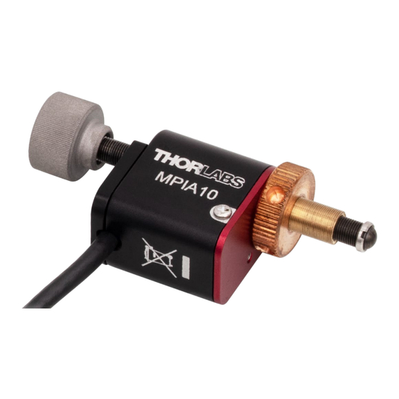
- Page 1 MPIA10 Mini Piezo Inertia Actuator User Guide...
- Page 2 MPIA10 Mini Piezo Inertia Actuator Table of Contents Chapter 1 Safety Information ....................1 1.1.1 General Cautions ............................1 1.1.2 General Notes ............................2 Chapter 2 Overview ....................... 3 Chapter 3 Installation ......................4 3.2.1 General ............................... 4 3.2.2 Fitting to a Threaded Mount ........................5 Chapter 4 Operation ......................
- Page 3 MPIA10 Mini Piezo Inertia Actuator Chapter 1: Safety Information Chapter 1 Safety Information For the continuing safety of the operators of this equipment, and the protection of the equipment itself, the operator should take note of the Warnings, Cautions and Notes throughout this handbook and, where visible, on the product itself.
- Page 4 MPIA10 Mini Piezo Inertia Actuator Chapter 1: Safety Information 1.1.2 General Notes Note The stick-slip nature of the mechanism uses a very short pulse width. Continuous stepping of the actuator results in an audible noise at a typical level of 60 to 70 dB.
- Page 5 10 - 30 nm can be achieved but may vary by up to 20% and is not normally repeatable. Thorlabs’ Mini Piezo Inertia Actuators have been designed for use with our range of small optical mounts and "...
- Page 6 MPIA10 Mini Piezo Inertia Actuator Chapter 3: Installation Chapter 3 Installation Environmental Conditions Warning Operation outside the following environmental limits may adversely affect operator safety. The unit is designed for indoor use only. To ensure reliable operation, the unit should not be exposed to corrosive agents or excessive moisture, heat, or dust.
- Page 7 4. Tighten the locking ring against the mount. Take care to avoid cross threading the ring. 5. Repeat items (1) to (4) for the remaining actuator. Figure 2 Fitting the MPIA10 to a KM05 Mirror Mount Rev. C, July 26, 2024 Page 5...
- Page 8 Chapter 3: Installation Electrical Connections The stage must be driven by a Thorlabs KIM101, KIM001 or legacy TIM101 controller. The MPIA series actuators feature an integrated 1 m (3.3') cable, terminated in an SMC connector. Connect the MPIA actuator to one of the MOT terminals on the rear panel of the controller - see the KIM101 or the KIM001 Controller handbook for pin out details.
- Page 9 Chapter 4 Operation General Caution The MPIA series actuators can only be driven by the Thorlabs KIM101, KIM001 or legacy TIM101 Controllers. Warning The piezo actuators in this product use high voltages. Voltages up to 130V may be present at the SMC connector.
- Page 10 MPIA10 Mini Piezo Inertia Actuator Chapter 4: Operation Caution If the actuator is driven into its end stops, the motor may stick and may not respond to subsequent motion demands. If this is the case, turn the adjustment knob of the actuator manually to move the device away from its end stop, then the motor should move normally.
- Page 11 A higher axial load is possible, but this may decrease the typical step size or stop the actuator from driving. The angular resolution when a MPIA10 Actuator is fitted to a KM05 Ø1/2" Mirror Mount at the maximum axial load of 13 N.
- Page 12 30% drop in step size may be experienced. What driver can I use? The piezo inertia actuators are designed to be driven by the Thorlabs KIM101 Inertia Piezo Driver. What is the maximum length of cable? The actuators feature an integrated 1m (3.3') of cable.
- Page 13 MPIA10 Mini Piezo Inertia Actuator Chapter 7: Certifications and Compliance Chapter 7 Certifications and Compliance Rev. C, July 26, 2024 Page 11...
- Page 14 MPIA10 Mini Piezo Inertia Actuator Chapter 8: Thorlabs Worldwide Contacts Chapter 8 Thorlabs Worldwide Contacts For technical support or sales inquiries, please visit us at for our most up-to-date www.thorlabs.com/contact contact information. USA, Canada, and South America UK and Ireland Thorlabs, Inc.
- Page 15 www.thorlabs.com...
Need help?
Do you have a question about the MPIA10 and is the answer not in the manual?
Questions and answers