
Related Manuals for THORLABS MPC220


Summary of Contents for THORLABS MPC220
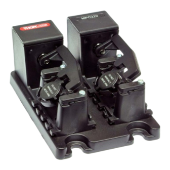
- Page 1 MPC220 and MPC320 Motorized Fiber Polarization Controller User Guide Original Instructions HA0383T...
-
Page 2: Table Of Contents
MPC220 and MPC320 Motorized Fiber Polarization Controllers Contents Chaper 1 Introduction ..........................1 Chaper 2 Safety ............................2 2.1 Safety Information ......................2 2.2 General Warnings and Cautions ..................2 Chaper 3 Overview ..........................3 3.1 2- and 3-Paddle Fiber Polarization Controllers ............3 3.2 Recommended Number of Loops .................. -
Page 3: Chapter 1 Introduction
Ø900 µm jacketed fiber). The MPC220 and MPC320 fiber polarization controllers have 2 and 3 paddles, respectively. These controllers are empty, which allows the user to install a fiber of their choice, and designed for use with Ø900 µm jacketed fiber. -
Page 4: Chapter 2 Safety
MPC220 and MPC320 Motorized Fiber Polarization Controllers Chapter 2 Safety 2.1 Safety Information For the continuing safety of the operators of this equipment, and the protection of the equipment itself, the operator should take note of the Warnings, Cautions, and Notes throughout this handbook and, where visible, on the product itself. -
Page 5: Chapter 3 Overview
Chapter 3 Overview Chapter 3 Overview 3.1 2- and 3-Paddle Fiber Polarization Controllers A 3-paddle polarization controller can be used as a quarter-wave plate, half-wave plate, and quarter-wave plate in series to transform an arbitrary polarization state into any other polarization state. The first quarter-wave plate would transform the input polarization state into a linear polarization state. -
Page 6: Recommended Number Of Loops
MPC220 and MPC320 Motorized Fiber Polarization Controllers 3.2 Recommended Number of Loops The retardation of multi-order (including zero-order) quarter-wave plates is given by the following equation: ----------------------- - where m is an integer. Similarly, the retardation of multi-order (including zero order) half-wave plates is given by: ... -
Page 7: Kinesis Software Overview
3.3.1 Introduction The MPC series polarization controllers share all the benefits of the Thorlabs range of device controllers and drivers. This includes USB connectivity (allowing multiple units to be used together on a single PC), fully featured graphical user interface (GUI) panels, and extensive software function libraries for custom application development. -
Page 8: Software Upgrades
Kinesis Controls collection. This is available either by pressing the F1 key when running the Kinesis server, or via the Start menu, Start\Programs\Thorlabs\Kinesis\Kinesis Help. 3.3.3 Software Upgrades Thorlabs operates a policy of continuous product development and may issue software upgrades as necessary. Page 6 ETN047599-D02... -
Page 9: Chapter 4 Mechanical Installation
The controller can be used in any orientation and at any angle. The base plate features a number of M6 (1/4”-20) clearance slots (3 for MPC220 and 4 for MPC320) to allow mounting to a standard 1" or 25 mm pitch optical table or breadboard as shown below. -
Page 10: Paddle Identification
MPC220 and MPC320 Motorized Fiber Polarization Controllers 4.3 Paddle Identification The individual paddles can be identified by numbers on the base as shown in Fig. 4.2. Paddle numbers (6 Places) Fig. 4.2 Paddle Identification Numbers Page 8 ETN047599-D02... -
Page 11: Chapter 5 Software & Electrical Installation
If you are in any doubt about your rights to install/run software, please consult your system administrator before attempting to install. If you experience any problems when installing software, contact Thorlabs and ask for Technical Support. DO NOT CONNECT THE STAGE TO YOUR PC YET 1) Download the software from www.thorlabs.com. -
Page 12: Verifying Software Operation
MPC220 and MPC320 Motorized Fiber Polarization Controllers 5.3 Verifying Software Operation 5.3.1 Initial Setup 1) Run the software and check that the GUI panel appears and is active. Fig. 5.1 Polarizer GUI Panel 2) Click the Home button to send each channel to the 85° (middle) position. This is the default ‘Home’ position, but it can be adjusted in the Settings panel to be anywhere between 0 and 170°... -
Page 13: Chapter 6 Setup
Chapter 6 Setup Chapter 6 Setup 6.1 Loading the Fiber 1) Using the Kinesis software, move the paddles to the 0° position. Caution Do not move the paddles by hand. This could damage the unit and invalidate the warranty. Fiber clamps removed 2) Orientate the unit as shown above with the paddles on the right, then remove the fiber clamps from all the paddles. - Page 14 MPC220 and MPC320 Motorized Fiber Polarization Controllers Fiber correctly routed through the upper guide 4) Loop the fiber round and, working from the left to right, feed the fiber into the upper guide in paddle 1. Do not pull or loop the fiber too tightly.
- Page 15 Chapter 6 Setup Fiber correctly routed through the guides in the paddle 7) Make more loops as required for the associated fiber type and wavelength - see Section 3.2. The minimum is one loop, the maximum is 4 loops. 8) Fit the second fiber clamp to the paddle 1. Fiber correctly routed through the upper guides on paddle 2 9) Loop the fiber from right to left and feed into the guides on paddle 2 as detailed in steps 3) to 4).
- Page 16 MPC220 and MPC320 Motorized Fiber Polarization Controllers 10) Repeat steps 5) to 8) for the remaining paddles 11) Working from left to right, feed the fiber into the exit guides in the base of the unit. Page 14 ETN047599-D02...
-
Page 17: Chapter 7 Operation - Tutorial
2) Connect the polarizer to the control PC using the USB cable provided. 3) Run the Kinesis program - Start/All Programs/Thorlabs/Kinesis/Kinesis. The server registers automatically the units connected on the USB bus and displays the associated GUI panels as shown in Fig. 7.1. -
Page 18: Homing Motors
MPC220 and MPC320 Motorized Fiber Polarization Controllers 7.3 Homing Motors Homing the motor moves the paddle to the zero limit switch. Note It is not necessary to ‘home’ the paddles before use as with other motorized actuators. The unit will recognize the paddle positions on power up. -
Page 19: Jogging
Chapter 7 Operation - Tutorial 7.5 Jogging During operation, the paddles are jogged using the GUI panel arrow keys. When the Jog button is clicked, the motor moves by the step size specified in the Jog Size parameter. If the jog key is held down, jogging is repeated until the button is released. 1) On the GUI panel, click the button to display the Jog Settings panel 2) Make parameter changes as required. -
Page 20: Chapter 8 Software Reference
MPC220 and MPC320 Motorized Fiber Polarization Controllers Chapter 8 Software Reference 8.1 Introduction This chapter gives an explanation of the parameters and settings accessed from the Kinesis software running on a PC. 8.2 GUI Panel The following screenshot shows the graphical user interface (GUI) displayed when accessing the polarization controller using the Kinesis software. -
Page 21: Settings Panel
Chapter 8 Software Reference Identify - When this button is pressed, the ACTIVE LED on the front panel of the associated hardware unit will flash for a short period. Settings - Displays the Settings panel, which allows the operating parameters to be entered for the motor drive - see Section 8.3. -
Page 22: Chapter 9 Specifications
MPC220 and MPC320 Motorized Fiber Polarization Controllers Chapter 9 Specifications Parameter MPC220 MPC320 Construction Material (Controller Body) Black Acrylonitrile Butadiene Styrene (ABS) Number of paddles 18 mm Loop Diameter (Ø900 µm Jacketed Fiber) Paddle Rotation 0 to 170° Compatible Fiber Ø900 µm Jacket Single Mode Fibers and Patch Cables... -
Page 23: Chapter 10 Regulatory
Chapter 10 Regulatory Chapter 10 Regulatory 10.1 Declarations Of Conformity 10.1.1 For Customers in Europe 10.1.2 For Customers In The USA This equipment has been tested and found to comply with the limits for a Class A digital device, pursuant to part 15 of the FCC rules. -
Page 24: Chapter 11 Thorlabs Worldwide Contacts
Contact Thorlabs for more information. Waste treatment is your own responsibility. "End of life" units must be returned to Thorlabs or handed to a company specializing in waste recovery. Do not dispose of the unit in a litter bin or at a public waste disposal site. - Page 25 www.thorlabs.com...
Need help?
Do you have a question about the MPC220 and is the answer not in the manual?
Questions and answers