Table of Contents
Advertisement
Quick Links
Advertisement
Table of Contents

Subscribe to Our Youtube Channel
Related Manuals for THORLABS MCM3000 Series


Summary of Contents for THORLABS MCM3000 Series
- Page 1 MCM3000 Series 3-Axis Controller User Guide...
- Page 2 MCM3000 Series Copyright © June 20, 2023 Thorlabs, Inc. All rights reserved. Information in this document is subject to change without notice. The software described in this document is furnished under a license agreement or nondisclosure agreement. The software may be used or copied only in accordance with the terms of those agreements.
-
Page 3: Table Of Contents
Description ................ 3 3.1. Features at a Glance ............. 3 Chapter 4 Getting Started ..............4 4.1. Unpacking and Inspection ..........4 4.2. Setting Up the MCM3000 Series ........5 4.2.1. Minimum Computer Requirements ..........5 4.2.2. Preparation ................5 Chapter 5 Software ................ -
Page 4: Chapter 1 Warning Symbol Definitions
MCM3000 Series Chapter 1: Warning Symbol Definitions Chapter 1 Warning Symbol Definitions Below is a list of warning symbols you may encounter in this manual or on your device. Symbol Description Direct Current Alternating Current Both Direct and Alternating Current... -
Page 5: Chapter 2 Safety
WARNING DO NOT use this device for anything other than its intended use. If the device is used in a manner not specified by Thorlabs, the protection provided by the equipment may be impaired. WARNING DO NOT operate in wet, damp, or explosive environment. -
Page 6: Chapter 3 Description
A smaller knob on the top face adjusts the amount of translation per rotation of the knob. Since each MCM3000 Series Controller has three axes, you only need to pur- chase enough controllers for each of the stages you intend to drive. For example, ®... -
Page 7: Chapter 4 Getting Started
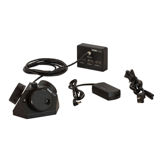
MCM3000 Series Chapter 4: Getting Started Chapter 4 Getting Started 4.1. Unpacking and Inspection Open the package, and carefully remove the MCM3000 Series and its accessor- ies. The table lists the standard accessories shipped with the device. Quantity MCM3001 MCM3002... -
Page 8: Setting Up The Mcm3000 Series
MCM3000 Series Chapter 4: Getting Started 4.2. Setting Up the MCM3000 Series 4.2.1. Minimum Computer Requirements Operating System Windows 7 or 10, 64 Bit Driver MCM3000.inf Visual C++ Redistributable Package (2012), Other Software Microsoft .NET 4.5.2 or later 4.2.2. Preparation We recommend you mount the 3-Axis Controller Box on an optical table or breadboard using the two included screws (M6 for metric, 1/4"-20x1/2"... - Page 9 MCM3000 Series Chapter 4: Getting Started Use the USB cable to connect the 3-Axis Controller Box to the computer. Note: This step is optional. Connect the USB port only if you want to use the software to control the position of the stages. The 3-Axis Knob Box or the software can control the position of the stages.
- Page 10 MCM3000 Series Chapter 4: Getting Started The 3-Axis Controller can control up to three axes. For example, the following diagram shows a MCM3001 controller connected to a PLS-XY translation stage and a ZFM2030 focusing module. Figure 3 Connecting the Controller Box to Different Stages Note: The MCM3002 Controller is shipped with adapter cables to connect the device to the stages (as shown in the diagram below).
- Page 11 MCM3000 Series Chapter 4: Getting Started Slide the power switch on the 3-Axis Controller Box to the On position. Figure 5 Power Switch on the 3-Axis Controller Box If you do not want to control the stages via USB, go to Step 8. To control the stages via USB, install the required software/driver on your computer as described in the Software Chapter on page 9.
-
Page 12: Chapter 5 Software
Insert the MCM3000 Installation CD into the computer and open the 70- 0033-4.0 MCM3000 SDK v4.0 folder. Alternatively, download the software from www.thorlabs.com. Double click the installer (.exe) application to open the MCM3000 4.0 Setup window. Click Next to continue. Figure 6 Thorlabs MCM3000 4.0 Setup Window Page 9 TTN040330-D02... - Page 13 Next. Figure 7 Choose Components Window In the Choose Install Location window, select the destination folder and then click Install. Figure 8 Thorlabs MCM3000 4.0 Setup Window Rev E, June 27, 2023 Page 10...
- Page 14 MCM3000 Series Chapter 5: Software During installation, the Device Driver Installation Wizard will appear. Click Next to begin installing the software drivers that some computer devices need in order to work. Figure 9 Device Driver Installation Wizard Window If prompted by Windows Security, select Install.
- Page 15 MCM3000 Series Chapter 5: Software Once drivers are installed, click Finish to continue. Figure 11 Device Driver Installation Wizard The installer will automatically search your computer for Microscoft Visual C++ Redistributable (x64) – 11.0.61030. It will download and install it if it's not found on your computer.
- Page 16 MCM3000 Series Chapter 5: Software Click Finish to complete the installation. Figure 13 Completing the Thorlabs MCM3000 4.0 Setup Window 10. MCM3000 software installation is now complete, and a new Windows shortcut is added to the desktop. Figure 14 MCM3000 Shortcut Icon 11.
- Page 17 MCM3000 Series Chapter 5: Software To change the COM Port Number to COM32: Right click on MCM3000 driver, and click on Properties to open the MCM3000 Properties window. Figure 15 Device Manager On the Port Settings tab, click Advanced to open the Advanced Settings window.
-
Page 18: Software Setup
MCM3000 Series Chapter 5: Software Select COM32 from the frop-down menu next to COM Port Number and click OK. Figure 17 Advanced Settings Window 12. Slide the Power switch on the Controller Box to the Off position, and then switch it on again. - Page 19 MCM3000 Series Chapter 5: Software The MCM3000 Control window appears. Before using the software to control the stages, it is necessary to configure that axes for the appropriate motor type. Verify that each stage is connected to the appropriate port depending on the axis of motion it controls...
- Page 20 MCM3000 Series Chapter 5: Software The Threshold value exists to prevent accidental commands that are larger than intended. If a movement command exceeds the Threshold value, it will prompt a warning message to appear asking to confirm the large stage move.
-
Page 21: Mcm3000 Gui (Graphical User Interface)
MCM3000 Series Chapter 5: Software 5.3. MCM3000 GUI (Graphical User Interface) The MCM3000 GUI consists of the menu and display area. Figure 20 MCM Control Window 5.3.1. Display Area The display area controls the movement of the modules, which are connected to the Controller Box. -
Page 22: Menu
MCM3000 Series Chapter 5: Software • Slider Step Size: Defines the increment of travel associated with click the plus or minus buttons on the interface. The coarse adjustment setting is always automatically 10 times larger than the fine adjustement setting. -
Page 23: Firmware
MCM3000 Series Chapter 5: Software 5.4. Firmware Note: It is only necessary to update the firmware if your device was purchased before 2017. If your device is using the old firmware, it will not run the new software. Check the power and USB are connected to the control box. Confirm that the power switch is in the OFF position. - Page 24 Replace it with the firmware.bin file found on the installation CD within the folder labeled 70-0012-1.3 MCM3000 Controller Firmware. The latest firmware can also be downloaded from www.thorlabs.com. Power cycle the controller box. Firmware installation is complete. Note: When the rest button is depressed during power-up, the controller box will revert to factory settings (using the original firmware it is shipped with).
-
Page 25: Chapter 6 Maintaining The Mcm3000 Series
Chapter 6: Maintaining the MCM3000 Series Chapter 6 Maintaining the MCM3000 Series Protect the MCM3000 Series from adverse weather conditions. The MCM3000 Series is not water resistant. The unit does not need regular maintenance. If you suspect a problem with the... - Page 26 MCM3000 Series Chapter 6: Maintaining the MCM3000 Series Problem Solution Push-Button Switch Does -Check the Joystick cable connection. Not Turn Green -Unplug and replug the power and USB connections. -Press and release the push-button switch a couple of times. Push-Button Switch -Make sure the stage connected to the respective axis is not at the end of its travel limit.
-
Page 27: Chapter 7 Specifications
MCM3000 Series Chapter 7: Specifications Chapter 7 Specifications 7.1. Controller Specifications Specification Values Item # MCM3001 MCM3002 Motor Output Motor Drive Voltage 24 V 7.0 A (Peak) Motor Drive Current 3.0 A (RMS) Motor Drive Type 12-Bit PWM Control Control Algorithm... -
Page 28: Compatible Motor Specifications
MCM3000 Series Chapter 7: Specifications 7.2. Compatible Motor Specifications Specification Value Motor Type 2-Phase Bi-Polar Stepper Rated Phase Current Up to 7 A Peak Step Angle Range 1.8° to 20° Motor Drive Mode Current 5 to 20 Ω Coil Resistance (Nominal) Coil Inductance (Nominal) 2 to 5.5 mH... -
Page 29: Chapter 8 Mechanical Drawing
MCM3000 Series Chapter 8: Mechanical Drawing Chapter 8 Mechanical Drawing Figure 26 3-Axis Knob Box Rev E, June 27, 2023 Page 26... - Page 30 MCM3000 Series Chapter 8: Mechanical Drawing Figure 27 Controller Box Description Description Stepper Motor Phase A+ Stepper Motor Phase B+ Stepper Motor Phase A- Stepper Motor Phase B- Not Used Not Used Not Used Ground Ground Encoder Phase A+ Encoder Phase B+...
- Page 31 MCM3000 Series Chapter 8: Mechanical Drawing Description Description Stepper Motor Phase A+ 1–6 Not Used Stepper Motor Phase A- Stepper Motor Phase A+ Not Used Stepper Motor Phase B+ Not Used 9–13 Not Used Stepper Motor Phase A- Ground Stepper Motor Phase B-...
-
Page 32: Chapter 9 Certificates And Compliance
MCM3000 Series Chapter 9: Certificates and Compliance Chapter 9 Certificates and Compliance Page 29 TTN040330-D02... -
Page 33: Chapter 10 Regulatory
Waste Treatment is Your Own Responsibility If you do not return an “end of life” unit to Thorlabs, you must hand it to a company specialized in waste recovery. Do not dispose of the unit in a litter bin or at a public waste disposal site. - Page 34 MCM3000 Series Chapter 10: Regulatory FCC Statement This product has been tested and found to comply with the limits according to IEC 61326-1 for using connection cables shorter than 3 meters (9.8 feet). This equipment has been tested and found to comply with the limits for a Class A...
-
Page 35: Chapter 11 Thorlabs Worldwide Contacts
MCM3000 Series Chapter 11: Thorlabs Worldwide Contacts Chapter 11 Thorlabs Worldwide Contacts For technical support or sales inquiries, please visit us at www.thorlabs.com/contact for our most up-to-date contact information. USA, Canada, and South America UK and Ireland Thorlabs, Inc. Thorlabs Ltd. - Page 36 www.thorlabs.com...
Need help?
Do you have a question about the MCM3000 Series and is the answer not in the manual?
Questions and answers