
Related Manuals for THORLABS BBD301


Summary of Contents for THORLABS BBD301
- Page 1 BBD30x Series Brushless DC Motor Controllers BBD301, BBD302, & BBD303 Brushless DC Motor Controllers Kinesis User Guide Original Instructions HA0427T...
-
Page 2: Table Of Contents
3.3. Electrical Installation ..................... 6 3.3.1. Connecting the Supply ....................6 3.3.2. Fuses ......................... 6 3.3.3. Rear Panel Connections BBD301 ................7 3.3.4. Rear Panel Connections BBD302 and BBD303 ............8 3.3.5. Configuring the Rear Panel BNC I/O Connectors ............8 3.4. - Page 3 BBD30x Series Brushless DC Motor Controllers 4.6. The Teach Facility: Inputting Stage Set-Points ..........15 4.7. The Knob Control: Setting Functionality ............16 4.8. Miscellaneous: Screen Brightness, Knob Sensitivity, Firmware Version, IP Address, Serial Number ..................16 4.9. Comments on Rotary Stages ................16 Chapter 5 PC Operation - Quick Start Guide ................
- Page 4 12.5. Starting a Synchronized Trajectory ..............67 Chapter 13 Regulatory ........................68 13.1. Declarations of Conformity ................68 13.1.1. For Customers in Europe ..................68 13.1.2. For Customers in the USA ..................68 Chapter 14 Thorlabs Worldwide Contacts ..................69 Page 2 ETN056124-D03...
-
Page 5: Chapter 1 Introduction And Overview
Similarly, home sequences have a full set of associated parameters that can be adjusted for a particular stage or actuator. For simplicity of operation, the Kinesis software incorporates pre-configured settings for each of the Thorlabs stages and actuators, while still exposing all parameters individually for use with other DC motor driven systems. -
Page 6: Kinesis Software Overview
1.2.1. Introduction As a member of the Thorlabs range of controllers, the BBD30x series DC motor controllers share many of the associated software benefits. This includes USB connectivity (allowing multiple units to be used together on a single PC), fully featured Graphical User Interface (GUI) panels, and extensive software function libraries for custom application development. -
Page 7: Software Upgrades
Download section of the website (https://www.thorlabs.com/software_pages/ViewSoftwarePage.cfm?Code=Motion_Control) 1.4. Software Upgrades Thorlabs operate a policy of continuous product development and may issue software upgrades as necessary. The latest software can be downloaded from the ‘Services’ section of www.thorlabs.com. 1.5. Ethernet Connectivity The Ethernet interface on the BBD30x controllers supports communication via TCP/IP. All commands have the same format and the bytes exchanged between the controller and the control PC are the same regardless of whether the underlying physical interface is USB or TCP/IP (Ethernet). -
Page 8: Chapter 2 Safety
BBD30x Series Brushless DC Motor Controllers Chapter 2: Safety Chapter 2 Safety 2.1. Safety Information For the continuing safety of the operators of this equipment, and the protection of the equipment itself, the operator should take note of the Warnings, Cautions and Notes throughout this handbook and, where visible, on the product itself. The following safety symbols may be used throughout the handbook and on the equipment itself. -
Page 9: Chapter 3 Installation
If you are in any doubt about your rights to install/run software, please consult your system administrator before attempting to install. If you experience any problems when installing software, contact Thorlabs on +44 (0)1353 654440 and ask for Technical Support. -
Page 10: Electrical Installation
The unit must be connected only to an earthed fused supply of 100 to 240 V. Use only power supply cables supplied by Thorlabs, other cables may not be rated to the same current. The unit is shipped with appropriate power cables for use in the UK, Europe and the USA. When shipped to other territories the appropriate power plug must be fitted by the user. -
Page 11: Rear Panel Connections Bbd301
BBD30x Series Brushless DC Motor Controllers Chapter 3: Installation 3.3.3. Rear Panel Connections BBD301 Figure 4 BBD301 Rear Panel Connections MOTOR DRIVE - Provides all phase current drive connections to the DC motor actuators, via a female 8-pin DIN connector – see Section 8.1. -
Page 12: Rear Panel Connections Bbd302 And Bbd303
BBD30x Series Brushless DC Motor Controllers Chapter 3: Installation 3.3.4. Rear Panel Connections BBD302 and BBD303 Figure 5 BBD302 Rear Panel Connections Figure 6 BBD303 Rear Panel Connections 3.3.5. Configuring the Rear Panel BNC I/O Connectors The BBD30x brushless motor controllers offer additional triggering functions that expand the triggering capabilities of the legacy BBD20X controllers. - Page 13 PID tuning. The BBD301 and BBD302 controllers provide two BNC trigger I/O ports whereas the BBD303 provides three. The configuration of the BNC I/O connectors and the associated motor channels is detailed in Section 6.4.1...
-
Page 14: Front Panel Controls And Indicators
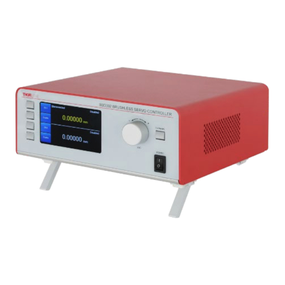
BBD30x Series Brushless DC Motor Controllers Chapter 3: Installation 3.4. Front Panel Controls and Indicators Figure 8 Front Panel Controls and Indicators Power - Rocker switch to turn power ON and OFF. Jog Knob - Used to initiate moves in normal operation. Main Display - In normal operation the display shows channel information, such as axis position and stage type connected. -
Page 15: Connecting The Hardware And Powering Up
BBD30x Series Brushless DC Motor Controllers Chapter 3: Installation 3.5. Connecting the Hardware and Powering Up Follow the set procedure for powering up, as described below. Specifically, a stage must only be connected to and disconnected from a controller that is powered down. 1) Install the Software - see Section 3.1. -
Page 16: Updating The Firmware
Updating the Firmware Caution Thorlabs often releases updated firmware for bug fixes and support for new features. We recommend all users to download the latest version of Kinesis software and use the included firmware update utility. Failure to do this could result in stages not being recognized by the latest controllers. -
Page 17: Chapter 4 Operation From The Front Panel
BBD30x Series Brushless DC Motor Controllers Chapter 3: Installation Chapter 4 Operation from the Front Panel 4.1. Introduction The BBD30x can be used to drive attached stages directly via the front panel controls and display screen, without the specific need of a computer connection and its peripheral software; only a mains power connection is needed, together with electrical connections to each stage (15-pin D plug, and 8-pin DIN plug for each stage). -
Page 18: System Startup
An example is shown in Figure 12b for a Thorlabs DDS220 linear stage. Where more stages are attached (for example when using a BBD302 or BBD303), information is also displayed in the Ch 2 and Ch 3 spaces. -
Page 19: Setting Motor Velocity And Acceleration
BBD30x Series Brushless DC Motor Controllers Chapter 3: Installation 4.4. Setting Motor Velocity and Acceleration Individual motor speed and acceleration can be set by first selecting the appropriate channel (which produces a screen similar to Figure 13b) then scrolling to the next page by pressing the lowest control panel button adjacent to "Next". This brings up a screen similar to Figure 14a, where Step Size, Velocity and Acceleration can all be changed. -
Page 20: The Knob Control: Setting Functionality
BBD30x Series Brushless DC Motor Controllers Chapter 3: Installation Figure 15 Stage position Set-points and Changing them via Teach 4.7. The Knob Control: Setting Functionality As noted in Section 4.5. the knob can control the motor stage position in either continuous-motion (default setting) or jog mode;... -
Page 21: Pc Operation - Quick Start Guide
BBD30x Series Brushless DC Motor Controllers Chapter 5: PC Operation - Quick Start Guide Chapter 5 PC Operation - Quick Start Guide 5.1. Introduction The Kinesis software suite includes a graphical user interface. The following provides a brief tutorial of the operation of the stage using the GUI controls, as well as an introduction to parameters that can be configured through the GUI. -
Page 22: Changing Motor Parameters And Moving To An Absolute Position
BBD30x Series Brushless DC Motor Controllers Chapter 5: PC Operation - Quick Start Guide 1) If the stage is not enabled, click the 'Enable' button (see Section 5.4). 2) After clicking on ‘Enable’ for first time use (to enable the motor), click the ‘Home’ button. Notice that the ‘Not Homed’ LED changes to ‘Homing’... -
Page 23: Disabling, Enabling And Stopping The Stage
BBD30x Series Brushless DC Motor Controllers Chapter 5: PC Operation - Quick Start Guide 5.4. Disabling, Enabling and Stopping the Stage The drive channel is enabled and disabled by clicking the ‘Enable’ button on the GUI panel or the front panel of the unit. The green indicator is lit when the drive channel is enabled. -
Page 24: Setting Move Sequences
BBD30x Series Brushless DC Motor Controllers Chapter 5: PC Operation - Quick Start Guide 5.6. Setting Move Sequences The Kinesis GUI allows move sequences to be programmed, allowing several positions to be visited without user intervention. For more details and instructions on setting move sequences, please see the Kinesis Help-file. Note that the Kinesis help-file can be access from within the GUI by clicking "Help"... -
Page 25: Chapter 6 Software Reference: Kinesis Gui Application
BBD30x Series Brushless DC Motor Controllers Chapter 6: Software Reference: Kinesis GUI Application Chapter 6 Software Reference: Kinesis GUI Application 6.1. Introduction The Kinesis software suite includes the Kinesis GUI application, Kinesis API with a library of DLL functions, a simulator, and stand-alone help files for both the GUI and simulator. - Page 26 BBD30x Series Brushless DC Motor Controllers Chapter 6: Software Reference: Kinesis GUI Application Jog Controls - Used to increment or decrement motor position. The Jog controls are a set of two arrows. The stage position is incremented or decremented by clicking the top or bottom arrow, respectively. There are two Jog modes, "Continuous"...
-
Page 27: Synchronized Moves
BBD30x Series Brushless DC Motor Controllers Chapter 6: Software Reference: Kinesis GUI Application 6.3. Synchronized Moves On BBD302 2-Axis and BBD303 3-Axis controllers, it is possible to perform synchronized moves by clicking the button to ‘group’ the channels. When this button is clicked, the Vector button and the path button become active. -
Page 28: Path Designer Synchronized Moves
CSV file, the data will be in device units. Conversion from device units to physical units is different for each stage and is detailed in the protocol document, available from www.thorlabs.com. The following sections describe the various path options available. -
Page 29: Circle
BBD30x Series Brushless DC Motor Controllers Chapter 6: Software Reference: Kinesis GUI Application 6.3.3. Circle The circle path designer produces a synchronized circular motion on 2 axes of the same controller. The entire motion consists of 3 distinct phases: Lead-in (acceleration) - This phase increases the velocity from zero to the specified value. This is performed horizontally, along the X-axis, towards the apex of the circle. -
Page 30: Circular Arc
BBD30x Series Brushless DC Motor Controllers Chapter 6: Software Reference: Kinesis GUI Application 6.3.4. Circular Arc The Circular Arc path designer produces a synchronized circular arc motion on 2 axes of the same controller. The entire motion consists of 3 distinct phases: Lead-in (acceleration) - This phase increases the velocity from zero to the specified value and is performed in a straight line towards point B. -
Page 31: Line Segment
BBD30x Series Brushless DC Motor Controllers Chapter 6: Software Reference: Kinesis GUI Application 6.3.5. Line Segment The line designer produces a synchronized line segment motion on 2 axes of the same controller. The entire motion consists of 3 distinct phases: Lead-in (acceleration) - This phase increases the velocity from zero to the specified value and is performed in a straight line towards point A. -
Page 32: Raster Scan
BBD30x Series Brushless DC Motor Controllers Chapter 6: Software Reference: Kinesis GUI Application 6.3.6. Raster Scan The raster scan designer produces a synchronized raster scan motion on 2 axes of the same controller. Per scan-line, the motion consists of several distinct phases: Lead-in (acceleration) - This phase increases the velocity from zero to the specified value and is performed in a straight line along the x-axis towards Ax. -
Page 33: Loading A Saved File
These are dependent on the type of controller and stage being used. For more detailed information on this, please consult the Host-Controller Communications Protocol document, available from www.thorlabs.com. To load a scan file, click the LOAD button and choose the required file from the list displayed. -
Page 34: Settings Panel
BBD30x Series Brushless DC Motor Controllers Chapter 6: Software Reference: Kinesis GUI Application 6.4. Settings Panel When the 'Settings' button on the GUI panel is clicked, the 'Settings' window is displayed. This panel allows motor operation parameters such as move/jog velocities, and stage/axis information to be modified. Note that each of these settings also can be read and updated using the Kinesis API. -
Page 35: Base Unit - I/O Tab
BBD30x Series Brushless DC Motor Controllers Chapter 6: Software Reference: Kinesis GUI Application 6.4.2. Base Unit - I/O Tab Figure 26 Base Unit I/O Settings Ports – The BNC connectors on the rear panel of the unit (1 for each motor channel) can be configured to be a Digital Input, a Digital Output or an Analog Output. -
Page 36: Channel Settings
BBD30x Series Brushless DC Motor Controllers Chapter 6: Software Reference: Kinesis GUI Application be made between 0… 0.01 mm or 10..70 mm), so in order to map these to the 0…+5V range, an offset and scale factor must be provided. Aux - In addition to the functionality provided by the BNC connectors, the AUX I/O connector (37-way D-type) on the rear panel provides further flexible options for connecting external digital I/O signals. -
Page 37: Moves/Jogs Tab
BBD30x Series Brushless DC Motor Controllers Chapter 6: Software Reference: Kinesis GUI Application 6.4.4. Moves/Jogs tab Figure 27 Move/Jog Settings Position Display Parameters By default, the GUI will display position in mm or degrees. If required, the units can be changed so that the display shows other positional units (cm, µm, in, rad, µrad.). - Page 38 BBD30x Series Brushless DC Motor Controllers Chapter 6: Software Reference: Kinesis GUI Application Enter a name for the new units, and a factor for conversion from millimetres, then click Add. The new units are added to the list and can now be selected in the Units parameter described previously. Once selected, click the Apply button to apply the new units.
- Page 39 BBD30x Series Brushless DC Motor Controllers Chapter 6: Software Reference: Kinesis GUI Application The two commands in the Velocity parameter grouping affect stage movement when the Move function in the Kinesis GUI is used to move the stage to an absolute position. The parameters in this Velocity group do not affect the velocity or acceleration of the stage when the Drive or Jog buttons are clicked.
-
Page 40: Stage/Axis Tab
For Thorlabs stages, the Kinesis API will automatically apply suitable defaults for the parameters on this tab during boot up of the software. Most of these parameters cannot subsequently be altered as it may adversely affect the performance of the stage and they are greyed out. - Page 41 Note For Thorlabs brushless motor-driven stages, the Homing, Limit Switch and Motor parameters described on the next two pages are not applicable for the DDS220 and MLS203 stages because the stage does not use a limit switch as a reference point for homing.
-
Page 42: Advanced Tab
BBD30x Series Brushless DC Motor Controllers Chapter 6: Software Reference: Kinesis GUI Application 6.4.6. Advanced Tab Figure 30 Advanced Control Loop Settings Position Loop (Stationary, Accelerating, and Constant Velocity) There are 3 sets of PID parameters, one for each stated move type, stationary, accelerating and constant velocity. This is an advanced feature for users who want to refine and optimize the controller's behavior in very sensitive applications. - Page 43 BBD30x Series Brushless DC Motor Controllers Chapter 6: Software Reference: Kinesis GUI Application Derivative Gain - Increasing the derivative (Deriv) term decreases the rate of change of driver output. Typically this is used to reduce the overshoot from a given motion. If Deriv is too high, it can become sensitive to noise from the measured position error;...
- Page 44 BBD30x Series Brushless DC Motor Controllers Chapter 6: Software Reference: Kinesis GUI Application Loop Type – If this box is unchecked, the user must select the current loop type (Default or Settled) using the parmeter settings that follow, and each loop type must be set separately. If this box is checked then all current loops use the same settings.
- Page 45 BBD30x Series Brushless DC Motor Controllers Chapter 6: Software Reference: Kinesis GUI Application 13) is set to 0 in the Status Register. When the position error returns to within the window boundary, the status bit is set to Tracking Window- Specifies the maximum allowed position error between the target and actual motor trajectory. Settle Window- Specifies the maximum allowed position error between the target and actual motor positions.
-
Page 46: Advanced - Misc. Tab
BBD30x Series Brushless DC Motor Controllers Chapter 6: Software Reference: Kinesis GUI Application 6.4.7. Advanced - Misc. Tab Figure 31 Advanced Miscellaneous Settings Velocity Profile Settings To prevent the motor from stalling, its velocity must be ramped up gradually to the required maximum. Certain limits to velocity and acceleration result from the torque and speed limits of the motor itself, and the inertia and friction of the parts it drives. - Page 47 Joystick Settings If the optional Thorlabs joystick console is being used (MJC001) the following parameters are used to set the velocity and acceleration limits and the direction sense of any moves initiated from the joystick - see Section 5.8 for more details on joystick use.
- Page 48 BBD30x Series Brushless DC Motor Controllers Chapter 6: Software Reference: Kinesis GUI Application Drive Array Velocities These parameters are the velocity settings programmed into the different Drive buttons on the GUI panel (see section 6.2). Each velocity setting in this tab is tied directly to a specific bar in the Drive bar graph (bottom, left). The velocity entered into the Velocity 1 field corresponds to the shortest Drive bar, the velocity entered into the Velocity 2 field corresponds to the next-shortest bar, and so on.
-
Page 49: Triggering Tab
BBD30x Series Brushless DC Motor Controllers Chapter 6: Software Reference: Kinesis GUI Application 6.4.8. Triggering Tab Figure 34 BBD30x Triggering Tab The BBD30x series controllers can be configured to respond to trigger inputs, generate trigger outputs, or perform both functions simultaneously. For example, a controller configured for both input and output triggering can initiate a move in response to a trigger input, while at the same time generating a trigger output. - Page 50 BBD30x Series Brushless DC Motor Controllers Chapter 6: Software Reference: Kinesis GUI Application Figure 36 Relative Move Settings Example Input Trigger options are set as follows: Disabled – triggering operation is disabled. GPI – General purpose input. Relative Move – a relative move (specified using the latest GUI panel settings) is initiated on the selected channel when an input signal is received.
- Page 51 BBD30x Series Brushless DC Motor Controllers Chapter 6: Software Reference: Kinesis GUI Application At Position Steps Rev - Trigger output active (pulsed) at pre-defined positions moving backwards. Only one Trigger port at a time can be set to this mode. See Trigger Out Position Steps below for further details. At Position Steps Both - Trigger output active (pulsed) at pre-defined positions moving forwards and backward.
- Page 52 BBD30x Series Brushless DC Motor Controllers Chapter 6: Software Reference: Kinesis GUI Application When the number of pulses set in the Cycle Count parameter has been generated, the trigger engine will schedule the next position to occur at the position specified in the Rev Start Position parameter. The same sequence as the forward direction is now repeated in reverse, except that the Reverse setting parameters apply.
-
Page 53: Defaults Tab
BBD30x Series Brushless DC Motor Controllers Chapter 6: Software Reference: Kinesis GUI Application 6.4.9. Defaults Tab Figure 39 BBD30x - Defaults Tab If adjustment of the parameter values previously described has resulted in unstable or unsatisfactory system response, this tab can be used to reset all parameter values to the factory default settings. To restore the default values, click the ‘Reset Stage to Factory Defaults’... -
Page 54: Rotation Stages Tab
BBD30x Series Brushless DC Motor Controllers Chapter 6: Software Reference: Kinesis GUI Application 6.4.11. Rotation Stages Tab Figure 40 Rotation Stages Tab Rotation Mode This setting relates to the way in which the angular position is displayed on the GUI panel. There are three options: Fixed Range - The angular rotation is limited to 360°... -
Page 55: Chapter 7 Kinesis Api Reference
The API command set is also described in the "APT_Communications_Protocol.pdf" reference available by visiting Thorlabs.com. , clicking on the Products menu, clicking on Software Downloads, Entering BBD301 in the search field, and then clicking on the "Download" button in the "Communications Protocol" Tab, as show in the following figures. - Page 56 BBD30x Series Brushless DC Motor Controllers Chapter 7: Kinesis API Reference Relative Move MGMSG_MOT_SET_MOVERELPARAMS 5.6, 6.4.8 Parameters (Triggered MGMSG_MOT_REQ_MOVERELPARAMS Sequenced Operations) MGMSG_MOT_GET_MOVERELPARAMS Initiate Relative Move MGMSG_MOT_MOVE_RELATIVE Absolute Move MGMSG_MOT_SET_MOVEABSPARAMS 5.6, 6.4.4, 6.4.8 Parameters (Move, MGMSG_MOT_REQ_MOVEABSPARAMS Triggered, Sequenced Operation) MGMSG_MOT_GET_MOVEABSPARAMS Initiate Absolute Move MGMSG_MOT_MOVE_ABSOLUTE 6.4.4 Initiate Continuous Move...
- Page 57 BBD30x Series Brushless DC Motor Controllers Chapter 7: Kinesis API Reference Limit Switch MGMSG_MOT_SET_LIMSWITCHPARAMS 6.4.5 Parameters MGMSG_MOT_REQ_LIMSWITCHPARAMS MGMSG_MOT_GET_LIMSWITCHPARAMS Move MGMSG_MOT_SET_LCDMOVEPARAMS 6.4.7 Parameters (Hardware MGMSG_MOT_SET_LCDMOVEPARAMS Control) MGMSG_MOT_SET_LCDMOVEPARAMS Enable / Disable MGMSG_MOD_SET_CHANENABLESTATE MGMSG_MOD_REQ_CHANENABLESTATE MGMSG_MOD_GET_CHANENABLESTATE Identify MGMSG_MOD_IDENTIFY Create Time-Position MGMSG_MOT_SET_MOVESYNCHARRAY Array for Synchronized Moves Output Time-Position...
- Page 58 BBD30x Series Brushless DC Motor Controllers Chapter 7: Kinesis API Reference MGMSG_MOT_GET_MOTOROUTPUTPARAMS Velocity Profile MGMSG_MOT_SET_PROFILEMODEPARAMS 6.4.7 MGMSG_MOT_REQ_PROFILEMODEPARAMS MGMSG_MOT_GET_PROFILEMODEPARAMS Front Panel Knob MGMSG_MOT_SET_LCDMOVEPARAMS 6.47 Parameters MGMSG_MOT_REQ_LCDMOVEPARAMS MGMSG_MOT_GET_LCDMOVEPARAMS Hardware Triggering MGMSG_MOT_SET_TRIGGER 6.4.8 footnote MGMSG_MOT_REQ_TRIGGER MGMSG_MOT_GET_TRIGGER Hardware Information MGMSG_HW_REQ_INFO 6.4.2 MGMSG_HW_GET_INFO Stage Axis Parameters MGMSG_MOT_SET_STAGEAXISPARAMS See Footnote MGMSG_MOT_REQ_STAGEAXISPARAMS...
- Page 59 BBD30x Series Brushless DC Motor Controllers Chapter 7: Kinesis API Reference MGMSG_MOT_GET_ENCCOUNTER Motor Channel Status MGMSG_MOT_GET_USTATUSUPDATE Update MGMSG_MOT_GET_USTATUSUPDATE MGMSG_MOT_GET_USTATUSUPDATE MGMSG_ MOT_REQ_STATUSBITS Suspend Resume MGMSG_ MOT_SUSPEND_ENDOFMOVEMSGS Certain Messages from MGMSG_ MOT_RESUME_ENDOFMOVEMSGS Controller Save Parameter Settings MGMSG_MOT_SET_EEPROMPARAMS for Specified Message Track / Settle: The Kinesis API command set provides a 'Tracking Window", which is not implemented in the Kinesis GUI .
-
Page 60: Chapter 8 Rear Panel Connector Pin-Out Details
Kinesis support software, these user programmable logic lines can be deployed in applications requiring control of external devices such a relays, light sources and other auxiliary equipment. The easy access BNC terminals currently allow for motor trigger inputs (one per motor; for BBD301, the second BNC present is not currently used). Page 56... - Page 61 BBD30x Series Brushless DC Motor Controllers Chapter 8: Rear Panel Connector Pin-out Details The AUX I/O pins are given in Figure 43, with the function details provided in the table below. Figure 43 AUX I/O Connector Pin Identification Page 57 Rev D April 2022...
-
Page 62: Differential Outputs
BBD30x Series Brushless DC Motor Controllers Chapter 8: Rear Panel Connector Pin-out Details Notes: Pins 1 & 2 are used for RS232 communications. This allows control of the device using the low level communications protocol, or other software environments such as micromanager. Pins 22-29 are single ended inputs and outputs - see Section A.3.3. -
Page 63: Supply
BBD30x Series Brushless DC Motor Controllers Chapter 8: Rear Panel Connector Pin-out Details A.3.4 Digital Inputs The digital inputs used in the controller are of the standard CMOS logic gate type with TTL compatible input levels and a built- in pull-up resistor (10 kΩ to +5V). They can be connected directly to mechanical switches, open-collector type outputs or most type of logic outputs. -
Page 64: Rear Panel Handset Connector
Figure 47 HANDSET Connector Pin Identification Note Pins 2, 3 and 6 are common (connected) ground connections. Pin 4 is for use only with Thorlabs joystick MJC001. It should not be used to power any other device. Page 60 ETN056124-D03... -
Page 65: Chapter 9 Using The Rs232 Or Virtual Comm Port
BBD30x Series Brushless DC Motor Controllers Chapter 9: Using the RS232 or Virtual Comm Port Chapter 9 Using the RS232 or Virtual Comm Port When using the low level communications protocol messages to develop client applications outside of the Kinesis software, communication with the device is facilitated by using the RS232 comms pins on the rear panel AUX I/O connector –... - Page 66 BBD30x Series Brushless DC Motor Controllers Chapter 9: Using the RS232 or Virtual Comm Port Select the ‘Advanced’ tab, and check the ‘Load VCP’ box. 5) Click OK, then power cycle the device being configured. 6) In the device manager, click ‘Ports (COM & LPT)’, and note the ‘USB Device Serial Port’ COM port number (e.g. COM3). This COM port can then be used by the client application to communicate with the device using the low level protocol messages.
-
Page 67: Chapter 10 Preventive Maintenance
BBD30x Series Brushless DC Motor Controllers Chapter 10: Preventive Maintenance Chapter 10 Preventive Maintenance 10.1. Safety Testing PAT testing in accordance with local regulations, should be performed on a regular basis, (typically annually for an instrument in daily use). 10.2. Fuses Two T 3.15A/250V a.c. -
Page 68: Chapter 11 Specifications
47 to 63 Hz General Housing Dimensions BBD301: 199.8 x 229.1 x 108.8 mm (7.87" x 9.02" x 4.28") (W x D x H) BBD302: 250.0 x 279.1 x 108.8 mm (9.84" x 10.99" x 4.28") BBD303: 350.0 x 279.1 x 108.8 mm (13.78" x 10.99" x 4.28") Weight BBD301: 1.20 kg (2.65 lbs) -
Page 69: Chapter 12 An Introduction To Multi-Axis Synchronized Moves
12.1. Introduction This section describes the implementation of multi-axis synchronized moves on the Thorlabs BBD30x series controllers. In order to give developers a better understanding of the underlying principles of multi-axis synchronized moves, the relevant building blocks of the BMC10X controller are shown below:... -
Page 70: Complex Move Shapes
BBD30x Series Brushless DC Motor Controllers Chapter 12: An Introduction to Multi-Axis Synchronized Moves Thus from the 2-D move parameters we can calculate the move parameters for each axis by simply multiplying Acc and Vel with the scaling factors: Thus: = Acc * Scale and Acc = Acc * Scale... -
Page 71: Repeated Patterns
BBD30x Series Brushless DC Motor Controllers Chapter 12: An Introduction to Multi-Axis Synchronized Moves 12.4. Repeated Patterns To make the scheme more flexible, a section of the curve can also be repeated for a number of times. With this extension, the array can be considered as having a leading, a repeated and a tailing section. -
Page 72: Chapter 13 Regulatory
BBD30x Series Brushless DC Motor Controllers Chapter 13: Regulatory Chapter 13 Regulatory 13.1. Declarations of Conformity 13.1.1. For Customers in Europe 13.1.2. For Customers in the USA This equipment has been tested and found to comply with the limits for a Class A digital device, pursuant to part 15 of the FCC rules. -
Page 73: Chapter 14 Thorlabs Worldwide Contacts
BBD30x Series Brushless DC Motor Controllers Chapter 14: Thorlabs Worldwide Contacts Chapter 14 Thorlabs Worldwide Contacts For technical support or sales inquiries, please visit us at www.thorlabs.com/contact for our most up-to-date contact information. Page 69 Rev D April 2022... - Page 74 www.thorlabs.com...
Need help?
Do you have a question about the BBD301 and is the answer not in the manual?
Questions and answers