Sungrow SP600S User Manual
Optimizer
Hide thumbs
Also See for SP600S:
- Quick installation manual (33 pages) ,
- User manual (69 pages) ,
- Quick installation manual (35 pages)
Table of Contents
Advertisement
Quick Links
Advertisement
Table of Contents

Subscribe to Our Youtube Channel
Related Manuals for Sungrow SP600S


Summary of Contents for Sungrow SP600S
- Page 1 User Manual OPtimizer SP600S SP600SOPtimizerUser ManualSP600S-UEN-Ver11-202203 SP600S-UEN-Ver11-202203...
-
Page 3: All Rights Reserved
Software Licenses • It is prohibited to use data contained in firmware or software developed by SUNGROW, in part or in full, for commercial purposes by any means. • It is prohibited to perform reverse engineering, cracking, or any other operations that... -
Page 4: About This Manual
Validity This manual applies to the following product: • SP600S It is referred to as "optimizer" hereinafter unless otherwise specified. Target Group This manual is intended for professional technicians who are responsible for installing, oper- ating, and maintaining the optimizer and users who need to check optimizer parameters. - Page 5 Indicates an imminently hazardous situation which, if not avoided, will result in death or serious injury. Indicates a moderately hazardous situation which, if not avoided, will result in death or serious injury. Indicates a slightly hazardous situation which, if not avoided, may result in minor or moderate injury.
-
Page 7: Table Of Contents
Contents All Rights Reserved .....................I About This Manual......................II 1 Safety Instructions ....................1 1.1 Unpacking and Inspection ................1 1.2 Installation Safety ...................1 1.3 Electrical Connection Safety................2 1.4 Operation Safety ....................3 1.5 Maintenance Safety ..................3 1.6 Disposal Safety ....................4 2 Product Description ..................5 2.1 System Introduction ..................5 2.2 Working Principle ...................6... - Page 8 5.5 Connecting to Inverter...................20 6 Commissioning ....................22 6.1 Inspection Before Commissioning..............22 6.2 Commissioning Procedure ................22 7 Optimizer Decommissioning .................23 7.1 Disconnecting Optimizer ................23 7.2 Dismantling Optimizer...................23 7.3 Disposal of Optimizer..................24 8 Troubleshooting and Maintenance ..............25 8.1 Troubleshooting ...................25 8.2 Maintenance ....................26 8.2.1 Maintenance Notices................26 8.2.2 Routine Maintenance ................27 8.2.3 Replacing Optimizer ................27...
-
Page 9: Safety Instructions
Perform operations considering ac- tual on-site conditions. • SUNGROW shall not be held liable for any damage caused by violation of gen- eral safety operation requirements, general safety standards, or any safety in- struction in this manual. -
Page 10: Electrical Connection Safety
1 Safety Instructions User Manual Before operating the product, please check and ensure that tools to be used have been maintained regularly. Electrical Connection Safety Before electrical connections, please make sure that the optimizer is not damaged. Otherwise, it may cause danger! Before electrical connections, please make sure that all switches connected to the optimizer are set to "OFF". -
Page 11: Operation Safety
User Manual 1 Safety Instructions Check the positive and negative polarity of the PV strings, and connect the PV con- nectors to corresponding terminals only after ensuring polarity correctness. During the installation and operation of the optimizer, please ensure that the posi- tive or negative polarities of PV strings do not short-circuit to the ground. -
Page 12: Disposal Safety
To avoid the risk of electric shock, do not perform any other maintenance opera- tions beyond this manual. If necessary, contact SUNGROW for maintenance. Otherwise, the losses caused are not covered by the warranty. Disposal Safety Please scrap the product in accordance with relevant local regulations and stan- dards to avoid property losses or casualties. -
Page 13: Product Description
Product Description System Introduction SP600S optimizer is mainly used to adjust the voltage and current of each PV module in real time to track the maximum power point of each module, thus improving the power genera- tion capacity of the PV system. It can also realize module-level shutdown, module-level IV curve scanning and automatic physical positioning. -
Page 14: Working Principle
2 Product Description User Manual figure 2-2 Application to Industrial and Commercial System Working Principle The working principle of the optimizer is shown in the diagram below. Connected to the PV module by its input cable, the optimizer can track the module's maximum power and output the desired voltage through a DC/DC voltage conversion circuit. -
Page 15: Product Introduction
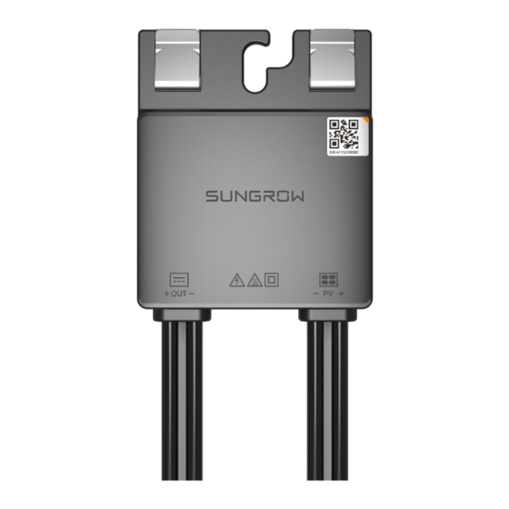
User Manual 2 Product Description figure 2-3 Working Principle Product Introduction Model Description figure 2-4 Model Description Product Appearance (A) Clips (B) Bolt hole (C) Input terminals (D) Output terminals... -
Page 16: Symbol Descriptions
2 Product Description User Manual Dimensions figure 2-6 Dimensions Symbol Descriptions Symbol Description Do not dispose of the optimizer as household waste. Read the manual before performing any operation on the optimizer. Comply with CE certification. EU/EEA imports. Comply with RCM certification. Hot surface with a temperature that may exceed 60 ℃. - Page 17 User Manual 2 Product Description Symbol Description Lethal high voltage! Only professional and qualified personnel can install and oper- ate the optimizer! Equipment protected by double insulation or reinforced insulation.
-
Page 18: Unpacking And Storage
• Check the inner contents for damage after unpacking. Contact SUNGROW or the transport company in case of any damage or incompleteness, and provide photos to facilitate services. Do not dispose of the original packing case. It is recommended to store the device in the ori- ginal packing case when the product is decommissioned. - Page 19 User Manual 3 Unpacking and Storage • Store the product in a clean and dry place with fine ventilation to prevent dust and water vapor from eroding. • Do not store the product in places with corrosive substances or susceptible to rodents and insects.
-
Page 20: Mechanical Mounting
Mechanical Mounting Respect all local standards and requirements during mechanical installation. Installation Location Selection Select an optimum installation location for a optimizer to operate safely, ensuring its service life and performance. • The optimizer is rated IP68. • It should be installed at a position convenient for electrical connection, operation and maintenance. -
Page 21: Installing Optimizer
User Manual 4 Mechanical Mounting Wire cutter Wire stripper Crimping tool Socket wrench (M8) Multimeter MC4 wrench Installing Optimizer The optimizer supports both clip installation and bolt installation. Please choose the appro- priate installation method according to the site conditions. 4.3.1 Preparation Before Installation Arrange the installation position of an optimizer reasonably to ensure that optimi- zer cables can be normally connected to the PV module and an adjacent optimi-... -
Page 22: 4.3.2 Installed On Aluminum Guide Rail
4 Mechanical Mounting User Manual 4.3.2 Installed on Aluminum Guide Rail step 1 It is recommended to use M8*25 T-head bolt assembly (not included in the scope of deliv- ery). Slide the T-head bolt into the groove in the aluminum guide rail. step 2 Hang the optimizer at the T-bolt through the bolt hole and fix it on the aluminum guide rail using a socket wrench in the order of nut, bolt hole and T-head bolt. -
Page 23: Installed On Steel Guide Rail (Bolt Assembly)
User Manual 4 Mechanical Mounting 4.3.4 Installed on Steel Guide Rail (Bolt Assembly) step 1 It is recommended to use M8*25 bolt assembly (not included in the scope of delivery). Insert the bolt assembly through the guide rail. step 2 Hang the optimizer at the bolt through the bolt hole and fix it on the steel guide rail using a socket wrench in the order of nut, bolt hole, spring washer, flat washer and bolt. -
Page 24: Electrical Connection
Electrical Connection Safety Precautions The PV string will generate lethal high voltage when exposed to sunlight. • Operators must wear proper personal protective equipment during electrical connections. • Must ensure that cables are voltage-free with a measuring instrument before touching DC cables. •... -
Page 25: Terminal Description
User Manual 5 Electrical Connection All electrical connections must comply with local and national/regional electrical standards. • Cables used by the user shall comply with the requirements of local laws and regulations. Comply with the safety instructions related to PV strings and the regulations re- lated to the local grid. -
Page 26: Mc4 Terminal Preparation
5 Electrical Connection User Manual MC4 Terminal Preparation In the process of connecting optimizers, if the distance between terminals is too long, it is necessary to prepare a pair of extension cables of suitable length with MC4 terminals at each end. The DC connector model of the optimizer is Staubli MC4. -
Page 27: Connecting To Pv Module
User Manual 5 Electrical Connection step 4 Connect the positive terminals of the PV connector to corresponding negative terminals until there is an audible click. - - End Connecting to PV Module Electric shock! Pay attention! PV arrays will generate lethal high voltage when exposed to sunlight. Ensure all cables are voltage-free before performing electrical operations. -
Page 28: Connecting To Inverter
5 Electrical Connection User Manual step 2 Connect the positive probe of a multimeter to OUT+ of the optimizer, and the negative probe of the multimeter to OUT- of the optimizer to check whether the optimizer is faulty. If the measured output voltage is between 0.9 V and 1.1 V, no fault occurs to the optimizer. - Page 29 User Manual 5 Electrical Connection If each PV module is equipped with an optimizer, the total power of PV modules in a PV input shall not exceed the maximum input power of a single PV input of the inverter.
-
Page 30: Commissioning
Commissioning Inspection Before Commissioning Check the following items before starting the optimizer: • All equipment has been reliably installed. • All cables are corrected connected. • Please check the input and output terminals of all optimizers for reversed connection. • All warning signs &... -
Page 31: Optimizer Decommissioning
Optimizer Decommissioning Disconnecting Optimizer Danger of burns! Even if the product is shut down, it may still be hot and cause burns. Wear protec- tive gloves before operating the optimizer after it cools down. step 1 The inverter connected to the optimizer is powered down. step 2 Ensure that the DC cable is current-free via a current clamp. -
Page 32: Disposal Of Optimizer
7 Optimizer Decommissioning User Manual Disposal of Optimizer Users take the responsibility for the disposal of the optimizer. Please scrap the optimizer in accordance with relevant local regulations and stan- dards to avoid property losses or casualties. Some parts of the optimizer may cause environmental pollution. Please dispose of them in accordance with the disposal regulations for electronic waste applicable at the installation site. -
Page 33: Troubleshooting And Maintenance
3. If the fault is not caused by the foregoing rea- put voltage sons and still exists, contact Sungrow Customer of the Service. optimizer. 1. Check whether the ambient temperature of the The ambi- device is too high. -
Page 34: Maintenance
To avoid the risk of electric shock, do not perform any other maintenance opera- tions beyond this manual. If necessary, contact SUNGROW for maintenance. Otherwise, the losses caused are not covered by the warranty. -
Page 35: 8.2.2 Routine Maintenance
User Manual 8 Troubleshooting and Maintenance 8.2.2 Routine Maintenance The maintenance item and period of the device are listed in the table below. Check Item Check Method Maintenance Period Check whether the device operates normally. Running status Once every six months Check whether there is abnormal noise or sound during operation. -
Page 36: Appendix
Appendix Technical Data Parameter Name SP600S Input Rated DC input power 600 W System max. allowable 1100 V voltage Max. PV input voltage 80 V MPP voltage range 8 ~ 80 V Max. DC short-circuit cur- rent (Isc) Output Max. output current Max. -
Page 37: Quality Assurance
• The customer shall give SUNGROW a reasonable period to repair the faulty device. Exclusion of Liability In the following circumstances, SUNGROW has the right to refuse to honor the quality guarantee: • The free warranty period for the whole machine/components has expired.
Need help?
Do you have a question about the SP600S and is the answer not in the manual?
Questions and answers