
Related Manuals for Sungrow SG8.0RS-L


Summary of Contents for Sungrow SG8.0RS-L
- Page 1 User Manual 1-Phase PV Grid-Connected Inverter SG8.0RS-L / SG9.0RS-L / SG10RS-L SG8.0RS-L / SG9.0RS-L / SG10RS-L1-Phase PV Grid-Connected InverterUser ManualSG8.0-10RS-L-UEN-Ver11- 202305 SG8.0-10RS-L-UEN-Ver11-202305...
-
Page 3: All Rights Reserved
Software Licenses • It is prohibited to use data contained in firmware or software developed by SUNGROW, in part or in full, for commercial purposes by any means. • It is prohibited to perform reverse engineering, cracking, or any other operations that... -
Page 4: About This Manual
Please read this manual carefully before using the product and keep it properly at a place for easy access. All contents, pictures, marks, and symbols in this manual are owned by SUNGROW. No part of this document may be reprinted by the non-internal staff of SUNGROW without written authorization. - Page 5 Symbols This manual contains important safety instructions, which are highlighted with the following symbols, to ensure personal and property safety during usage, or to help optimize the prod- uct performance in an efficient way. Please carefully understand the meaning of these warning symbols to better use the manual. Indicates high-risk potential hazards that, if not avoided, may lead to death or seri- ous injury.
-
Page 7: Table Of Contents
Contents All Rights Reserved .....................I About This Manual......................II 1 Safety Instructions ....................1 1.1 Unpacking and Inspection ................2 1.2 Installation Safety ...................2 1.3 Electrical Connection Safety................3 1.4 Operation Safety ....................4 1.5 Maintenance Safety ..................5 1.6 Disposal Safety ....................6 2 Product Description ..................7 2.1 System Introduction ..................7 2.2 Product Introduction..................8... - Page 8 5.2 Terminal Description ..................28 5.3 Electrical Connection Overview ..............28 5.4 External Protective Grounding Connection .............30 5.4.1 External Protective Grounding Requirements ........30 5.4.2 Connection Procedure.................31 5.5 AC Cable Connection ...................32 5.5.1 AC Side Requirements ................32 5.5.2 Connecting the AC Cable ..............33 5.6 DC Cable Connection ...................35 5.6.1 PV Input Configuration ................37 5.6.2 Assembling the PV Connectors ............38...
- Page 9 7.10.3 Power Regulation Parameters............68 7.10.4 Communication Parameters...............73 7.10.5 Firmware Update ................73 8 System Decommissioning ................75 8.1 Disconnecting Inverter ..................75 8.2 Dismantling the Inverter ................75 8.3 Disposal of Inverter..................76 9 Troubleshooting and Maintenance ..............77 9.1 Troubleshooting ...................77 9.2 Maintenance ....................84 9.2.1 Maintenance Notices................84 9.2.2 Routine Maintenance ................86 10 Appendix .......................87...
-
Page 11: Safety Instructions
Perform operations considering ac- tual onsite conditions. • SUNGROW shall not be held liable for any damage caused by violation of gen- eral safety operation requirements, general safety standards, or any safety in- struction in this manual. -
Page 12: Unpacking And Inspection
If there are problems with the above inspection items, do not install the device and contact your distributor first. If the problem persists, con- tact SUNGROW in time. Installation Safety •... -
Page 13: Electrical Connection Safety
User Manual 1 Safety Instructions Electrical Connection Safety • Before electrical connections, please make sure that the inverter is not dam- aged, otherwise it may cause danger! • Before electrical connections, please make sure that the inverter switch and all switches connected to the inverter are set to "OFF", otherwise electric shock may occur! The PV string will generate lethal high voltage when exposed to sunlight. -
Page 14: Operation Safety
1 Safety Instructions User Manual • Check the positive and negative polarity of the PV strings, and connect the PV connectors to corresponding terminals only after ensuring polarity correctness. • During the installation and operation of the inverter, please ensure that the posi- tive or negative poles of PV strings do not short-circuit to the ground. -
Page 15: Maintenance Safety
To avoid the risk of electric shock, do not perform any other maintenance opera- tions beyond those described in this manual. If necessary, contact your distributor first. If the problem persists, contact SUNGROW. Otherwise, the losses caused is not covered by the warranty. -
Page 16: Disposal Safety
1 Safety Instructions User Manual • If the paint on the inverter enclosure falls or rusts, repair it in time. Otherwise, the inverter performance may be affected. • Do not use cleaning agents to clean the inverter. Otherwise, the inverter may be damaged, and the loss caused is not covered by the warranty. -
Page 17: Product Description
The intended usage of the inverter is illustrated in the following figure. figure 2-1 Inverter Application in PV Power System Description Item Note Compatible with monocrystalline silicon, polycrystalline silicon, PV strings and thin-film modules without grounding. SG8.0RS-L, SG9.0RS-L, SG10RS-L. Inverter Metering device Meter cupboard with power distribution system. -
Page 18: Product Introduction
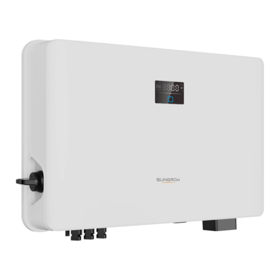
2 Product Description User Manual Description Item Note Utility grid TT,TN-C,TN-S, TN-C-S. House loads that consume electricity. Loads The following figure shows the common grid configurations. Product Introduction Model Description The model description is as follows (take SG8.0RS—L as an example): Appearance The following figure shows the appearance of the inverter. - Page 19 User Manual 2 Product Description figure 2-2 Inverter Appearance Description Name To safely disconnect the DC circuit whenever necessary. DC switch Complement to the included wall mounting bracket for hang- Hanger ing the inverter. The LCD screen indicates the running information and the LCD panel LED indicator indicates the working state of the inverter.
-
Page 20: Symbols On Product
2 Product Description User Manual figure 2-3 Dimensions of the Inverter Inverter Model W (mm) H (mm) D (mm) SG8.0RS-L, SG9.0RS-L, SG10RS-L 170.5 Symbols on Product Symbol Explanation Parameters on the DC side. Parameters on the AC on-grid side. Regulatory compliance mark. -
Page 21: Led Panel
User Manual 2 Product Description Symbol Explanation Burn danger due to the hot surface that may exceed 60℃. Danger to life due to high voltages! Do not touch live parts for 10 minutes after disconnection from the power sources. Only qualified personnel can open and maintain the inverter. External protective grounding terminal. -
Page 22: Circuit Diagram
2 Product Description User Manual table 2-1 State description of the LED indicator LED color State Definition The inverter is operating normally. The inverter is at standby or startup state (not Flashing feeding power into the grid). Blue A system fault has occured. Both the AC and DC sides are powered down. -
Page 23: Function Description
After communication connection is established, users can view inverter information, operational data and can set inverter parameters through the iSolarCloud. It is recommended to use the communication module from SUNGROW. Using a device from other companies may lead to communication failure or other... - Page 24 2 Product Description User Manual • Protection Function Several protective functions are integrated in the inverter, including short circuit protection, grounding insulation resistance monitoring, residual current protection, grid monitoring, DC overvoltage/overcurrent protection, etc. DRM ("AU"/"NZ") The DRM function is only applicable to a single inverter. The inverter provides terminals for connecting to a Demand Response Enabling Device (- DRED).
- Page 25 User Manual 2 Product Description figure 2-6 PID Risk of Traditional Inverters The following figure is the PID risk of the inverter equipped with PID Zero, it prevents the PV array voltage from approaching PV-, reduces the risk of PID during daily operation and repairs PV panels caused by PID at night.
- Page 26 2 Product Description User Manual • When the PID Zero function is enabled, there will be a power consumption of less than 30 W in the PID Zero process. • PID Zero can be applied to P-type PV panels, as well as N-type PV panels of which the voltage between PV- and ground needs to be raised.
-
Page 27: Unpacking And Storage
• Check the inner contents for damage after unpacking. Contact SUNGROW or the transport company in case of any damage or incompleteness, and provide photos to facilitate services. Do not dispose of the original packing case. It is recommended to store the device in the original packing case when the product is decommissioned. - Page 28 3 Unpacking and Storage User Manual • Do not place the inverter in places with items that may affect or damage the inverter. • Store the inverter in a clean and dry place to prevent dust and water vapor from eroding. •...
-
Page 29: Mechanical Mounting
Mechanical Mounting Respect all local standards and requirements during mechanical installation. Safety During Mounting Make sure there is no electrical connection before installation. Before drilling, avoid the water and electricity wiring in the wall. Poor installation environment will affect system performance! •... -
Page 30: Location Requirements
4 Mechanical Mounting User Manual Location Requirements To a large extent, a proper installation location ensures safe operation, service life, and per- formance of the inverter. • The inverter with protection rating IP65 can be installed both indoors and outdoors. •... -
Page 31: Angle Requirements
User Manual 4 Mechanical Mounting 4.2.3 Angle Requirements Install the inverter vertically. Never install the inverter horizontally, or at forward/backward tilted, side tilted, or upside down. 4.2.4 Clearance Requirements Reserve enough clearance around the inverter to ensure sufficient space for heat dissipation. -
Page 32: Installation Tools
4 Mechanical Mounting User Manual Install the inverter at an appropriate height for ease of viewing the screen and LED indicator and operating switch(es). Installation Tools Installation tools include but are not limited to the following recommended ones. If necessary, use other auxiliary tools on site. -
Page 33: Moving The Inverter
User Manual 4 Mechanical Mounting OT terminal crimp- MC4 terminal Electric screwdriver Slotted screwdriver ing tool (4 mm –6 crimping tool (0.5 (M4, M5, M6) (M2) –1.0 mm Phillips screwdriver Vacuum cleaner Measuring tape Heat shrink tubing (M4) Heat gun Open-end wrench Connector wrench Multimeter (≥... -
Page 34: Installing The Inverter
4 Mechanical Mounting User Manual Improper handling may cause personal injury! • Arrange an appropriate number of personnel to carry the inverter according to its weight, and installation personnel should wear protective equipment such as anti-impact shoes and gloves. • Attention must be paid to the center of gravity of the inverter to avoid tilting dur- ing handling. - Page 35 User Manual 4 Mechanical Mounting * The image shown here is for reference only. The actual product received may differ. step 2 Place the expansion tubes into the holes. Then secure the wall-mounting bracket to the wall firmly with the expansion bolt sets. step 3 Lift the inverter and slide it down along the wall-mounting bracket to make sure they match perfectly.
-
Page 36: Electrical Connection
Electrical Connection Safety Instructions The PV string will generate lethal high voltage when exposed to sunlight. • Operators must wear proper personal protective equipment during electrical connections. • Must ensure that cables are voltage-free with a measuring instrument before touching DC cables. •... - Page 37 User Manual 5 Electrical Connection All electrical connections must comply with local and national/regional electrical standards. • Cables used by the user shall comply with the requirements of local laws and regulations. • Only with the permission of the national/regional grid department, the inverter can be connected to the grid.
-
Page 38: Terminal Description
5 Electrical Connection User Manual The cable colors in figures in this manual are for reference only. Please select ca- bles according to local cable standards. Terminal Description All electrical terminals are located at the bottom side of the inverter. figure 5-1 Terminals * The image shown here is for reference only. - Page 39 Outdoor single-core Grounding 4 mm ~ 10 mm 6 mm ~ 10mm copper wire cable cable SG8.0RS-L: 16 SG8.0RS-L: 8 mm ~ 10 mm ~ 22 mm Outdoor 3-core AC cable SG9.0/10RS-L: copper wire cable SG9.0/10RS-L: 10 mm 18 mm ~ 25.8 16 mm (1) All the AC wires should be equipped with correctly colored cables for distinguishing.
-
Page 40: External Protective Grounding Connection
AC side grounding terminal are reliably grounded. The grounding connection can be made by other means if they are in accordance with the local standards and regulations, and SUNGROW shall not be held liable for the possible consequences. -
Page 41: Connection Procedure
User Manual 5 Electrical Connection When there are multiple inverters in the PV system, connect the external protective ground- ing terminals of all inverters and the grounding points of the PV module brackets to ensure equipotential connections to ground cables (according to the onsite conditions). 5.4.2 Connection Procedure External grounding cable and OT/DT terminal are prepared by customers. -
Page 42: Ac Cable Connection
An independent two-pole circuit breaker must be installed on the output side of the inverter to ensure safe disconnection from the grid. The recommended specifications are as follows. Recommended Specification Inverter Model SG8.0RS-L/SG9.0RS-L SG10RS-L 63 A Testing to AS/NNZS 4777.2:2020 Section for multiple phase combinations has not... -
Page 43: Connecting The Ac Cable
User Manual 5 Electrical Connection AC circuit breakers should be installed on the output side of the inverter and the grid side to ensure safe disconnection from the grid. • Determine whether an AC circuit breaker with greater overcurrent capacity is re- quired based on actual conditions. - Page 44 5 Electrical Connection User Manual step 4 Crimp the OT/DT terminal. step 5 Fix all the wires to the terminals according to the assignment and tighten to a torque of 2.0 N•m with a screwdriver. Observe the terminal assignment. Do not connect any phase line to the "PE" termi- nal or PE wire to "N"...
-
Page 45: Dc Cable Connection
User Manual 5 Electrical Connection step 6 Secure the AC waterproof cover to the inverter with a torque of 0.5 N•m and tighten the swiv- el nut to a torque of 5 N•m–6 N•m. step 7 Connect the PE wire to ground and the phase lines and the “N” line to AC circuit breaker. Then connect the AC circuit breaker to electric board. - Page 46 5 Electrical Connection User Manual • Make sure the PV array is well insulated to ground before connecting it to the inverter. • Make sure the maximum DC voltage and the maximum short circuit current of any string never exceed inverter permitted values specified in "Technical Data". •...
-
Page 47: Pv Input Configuration
5.6.1 PV Input Configuration • The inverters SG8.0RS-L/SG9.0RS-L/SG10RS-L have three PV inputs, each with inde- pendent MPP tracker. Each DC input area can operate independently. • The PV strings to each DC input may differ from each other, including PV module type, number of PV modules in each string, angle of tilt, and installation orientation. -
Page 48: Assembling The Pv Connectors
5 Electrical Connection User Manual 5.6.2 Assembling the PV Connectors High voltage may be present in the inverter! • Ensure all cables are voltage-free before performing electrical operations. • Do not connect the DC switch and AC circuit breaker before finishing electrical connection. -
Page 49: Installing The Pv Connectors
User Manual 5 Electrical Connection step 4 Check for polarity correctness. If the PV polarity is reversed, the inverter will be in a fault or alarm state and will not operate normally. - - End 5.6.3 Installing the PV Connectors step 1 Rotate the DC switch to "OFF"... -
Page 50: Wifi-P2 Connection
5 Electrical Connection User Manual - - End WiFi-P2 Connection The WiFi-P2 module supports WLAN communication. 5.7.1 WLAN Communication step 1 Remove the waterproof lid from the COM1 terminal. step 2 Install the module. Slightly shake it by hand to determine whether it is installed firmly, as shown below. -
Page 51: Commissioning
Commissioning Inspection Before Commissioning Check the following items before starting the inverter: • All equipment has been reliably installed. • DC switch(es) and AC circuit breaker are in the "OFF" position. • The ground cable is properly and reliably connected. •... -
Page 52: Creating A Plant
"7.3 Account Registration". If you have got the account and password from the distributor/installer or SUNGROW, skip this step. step 3 Download the firmware package to the mobile device in advance. Refer to “Firmware Upa- date”. This is to avoid download failure due to poor on-site network signal. - Page 53 User Manual 6 Commissioning step 4 Fill in the content according to actual needs, and the parameters containing * are required. Tap Next to enter the next interface. figure 6-2 Plant Creation Settings Parameter Description Name Plant name The name of the plant. Plant type The type of the plant, which should be set corresponding to the actual plant type.
- Page 54 6 Commissioning User Manual Parameter Description Name Time zone The time zone where the plant is located, which can be filled through automatic positioning and manual input. The location of the plant, which can be filled in two ways: • Manually: Manually enter the plant location in the input box.
- Page 55 User Manual 6 Commissioning step 6 After a device is bound, tap Device and Commissioning to go to corresponding interface. step 7 Tap Network Configuration to go to the WLAN connection interface. Tap the home net- work in the WLAN list, enter the password, and then tap Confirm.
- Page 56 6 Commissioning User Manual step 8 Enter the Activate EasyConnect interface, and press the multi-function button on the WiFi —P2 to enable the Easyconnect mode according to the prompt on the screen. The App au- tomatically enters a waiting processing interface if this mode is enabled, and automatically returns to the commissioning interface after the processing is completed.
- Page 57 User Manual 6 Commissioning When the country is set to Australia, additionally set the applicable network service provider and then the grid type. The image shown here is for reference only. Refer to the actual interface for the supported network service providers.
- Page 58 6 Commissioning User Manual table 6-1 Description of Network Service Provider and Grid Type Network Service Provider Grid Type AS/NZS 4777.2:2015 AS/NZS 4777.2:2020 Australia A AS/NZS 4777.2:2020 Australia B AS/NZS 4777.2:2020 Australia C • STNW1170: single-phase < 10 kVA & ENERGEX &...
-
Page 59: Initializing The Device
User Manual 6 Commissioning • Please check the country supported by this product at http:// support.sungrow- power.com/. • Set Country/Region to the country/region where the inverter is installed. Oth- erwise, the inverter may report a fault. step 10 After a plant is successfully created, return to the App home page to view the plant information. - Page 60 6 Commissioning User Manual figure 6-4 Upgrading Inverter If the communication equipment is upgraded, after successful upgrade, check and confirm that the phone is connected to the inverter WLAN. step 3 Tap Country/Region and select the country where the inverter is installed at. The supported countries and corresponding settings are as follows.
- Page 61 User Manual 6 Commissioning The image shown here is for reference only. Refer to the actual interface for the supported network service providers. table 6-2 Description of Network Service Provider and Grid Type Network Service Provider Grid Type AS/NZS 4777.2:2015 AS/NZS 4777.2:2020 Australia A AS/NZS 4777.2:2020...
-
Page 62: Configuring The Plant
6 Commissioning User Manual Network Service Provider Grid Type • UE-ST-2008.1: ≤ 10 kVA for single- phase & 30 kVA for three-phase United Energy • UE-ST-2008.2: > 30 kVA three-phase Embedded Generation Notice Photovoltaic PowerWater Systems:2020 • TS129-2019: < 10 kW for single-phase &... - Page 63 User Manual 6 Commissioning The distributor/installer who creates a plant for the end user needs to get the end user's e- mail address. In configuring a plant, the e-mail address is required, and each e-mail address can be registered only once. step 1 The App screen will display the added inverter.
- Page 64 6 Commissioning User Manual figure 6-8 Entering Tariff Information step 4 Fill in the end user's e-mail address. The first time you fill in the end user's e-mail address, the system will create an account for the end user and send an email to the end user. The end user can activate the account via the email.
- Page 65 Tab the inverter to view the live data about voltage, current, power or curve. Contact Sungrow service to enable live data function of devices. Once enabled, live data function is available for 3 hours per day by default. To make it available for 24 hours, contact SUNGROW.
-
Page 66: Isolarcloud App
App. * To achieve direct login via WLAN, the wireless communication module developed and manufactured by SUNGROW is required. The iSolarCloud App can also establish communi- cation connection to the inverter via Ethernet connection. -
Page 67: Account Registration
User Manual 7 iSolarCloud App Account Registration The account distinguishes two user groups, end user and distributor/installer. • The end user can view plant information, create plants, set parameters, share plants, etc. • The distributor/installer can help the end user to create plants, manage, install, or main- tain plants, and manage users and organizations. -
Page 68: Login
7 iSolarCloud App User Manual step 4 Fill in the registration information, including email, verification code, password and affirm- ance and country (region). The distributor/installer has the permission to fill in the company name and the code of upper level installer/distributor. The code of upper level distributor/installer can be obtained from the upper level distributor/installer. - Page 69 User Manual 7 iSolarCloud App figure 7-1 Enabling the WLAN Hotspot step 2 Connect the mobile phone to the WLAN network named as "SG-xxxxxxxxxxx" (xxxxxxxxxxx is the serial number indicated on the side of the communication module). step 3 Open the App to enter the login screen. Tap Local Access to enter the next screen. step 4 Tap Confirm, then enter the password and tap LOGIN.Or tap MANUAL CONNECTION at the bottom of the interface and select WiFi-P2, then enter the password and tap LOGIN.
-
Page 70: Initial Settings
7 iSolarCloud App User Manual figure 7-3 WLAN Local Access step 6 After finishing the settings, tap TUNR ON DEVICE at the upper right corner and the device will be initialized. The App will send start instructions and the device will start and operate. step 7 After initialization settings, the App will return automatically to the home page. -
Page 71: Function Overview
User Manual 7 iSolarCloud App The actual initializing procedure may differ due to different countries. Please fol- low the actual App guidance. Function Overview The App provides parameter viewing and setting functions, as shown in the following figure. figure 7-4 App Function Tree Map Home Home page of the App is shown in the following figure. -
Page 72: Run Information
7 iSolarCloud App User Manual figure 7-5 Home table 7-1 Home Page Description Description Name Present operation state of the inverter Inverter state Shows the PV power generation power, feed-in power, etc. Energy flow The line with an arrow indicates energy flow between con- chart nected devices, and the arrow pointing indicates energy flow direction. -
Page 73: Records
User Manual 7 iSolarCloud App table 7-2 Description of Run Information Description Item Shows basic information such as running state, on-grid running time, Inverter negative voltage to grid, bus voltage, internal air temperature, inver- Information ter efficiency, etc. Shows total DC power, voltage and current of MPPT1 ,MPPT2 and Input MPPT3. - Page 74 7 iSolarCloud App User Manual figure 7-7 Chart The App displays power generation records in a variety of forms, including daily power gen- eration graph, monthly power generation histogram, annual power generation histogram and total power generation histogram. table 7-3 Description of Power Curve Description Item Daily...
- Page 75 User Manual 7 iSolarCloud App figure 7-8 Fault Alarm Record Click to select a time segment and view corresponding records. Select one of the records in the list and click the record, to view the detailed fault info as shown in following figure. figure 7-9 Detailed Fault Alarm Information Event Record Tap Event Record to enter the screen, as shown in the following figure.
-
Page 76: More
7 iSolarCloud App User Manual figure 7-10 Event Record Click to select a time segment and view corresponding records. 7.10 More Tap More on the navigation bar to enter the corresponding screen, as shown in the following figure. figure 7-11 More In addition to viewing the WLAN configuration and App software version, the More screen supports the following operations: •... -
Page 77: System Parameters
User Manual 7 iSolarCloud App 7.10.1 System Parameters Tap Settings→System Parameters to enter the corresponding interface, as shown in the following figure. figure 7-12 System Parameters * The image shown here is for reference only. Boot/Shutdown Tap Boot/Shutdown to send the boot/shutdown instruction to the inverter. For Australia and New Zealand, when the DRM state is DRM0, the "Boot"... -
Page 78: Power Regulation Parameters
7 iSolarCloud App User Manual figure 7-14 PID Setting table 7-4 PID Parameter Description Description Parameter Set enabling/disabling of the PID night recovery function. PID night PID Recovery recovery function operates between 22:00 pm and 5:00 am by default. The Anti-PID function is performed during the day when connected Anti-PID to the grid. - Page 79 User Manual 7 iSolarCloud App figure 7-15 Active Power Regulation table 7-5 Description of Active Power Regulation Parameters Description Range Parameter Active Power Soft Start Switch for activating/deactivating the function On/Off after Fault of active power soft start after a fault occurs Active Power Soft Start The soft start time required for raising active 1 s–1200 s...
- Page 80 7 iSolarCloud App User Manual figure 7-16 Reactive Power Regulation table 7-6 Description of Reactive Power Regulation Parameters Description Range Parameter Reactive Power Set- Switch for activating/deactivating the function On/Off ting Persistence of reactive power setting persistence Reactive Power Regu- Off/PF/Qt/Q Off/PF/Qt/Q(P)/Q(U) lation Mode...
- Page 81 User Manual 7 iSolarCloud App table 7-7 "Q(P)" Mode Parameters Explanation Parameter Explanation Range Q(P) Curve Select corresponding curve according to local A, B, C regulations QP_P1 Output power at point P1 on the Q(P) mode curve 0.0 %–100.0 % (in %) QP_P2 Output power at point P2 on the Q(P) mode curve...
- Page 82 7 iSolarCloud App User Manual The reactive power output of the inverter varies in response to the grid voltage. table 7-8 "Q(U)" Mode Parameter Explanation Explanation Range Parameter Select corresponding curve according to local Q(U) curve A, B, C regulations Hysteresis Voltage hysteresis ratio on the Q(U) mode curve 0.0 %–5.0 %...
-
Page 83: Communication Parameters
User Manual 7 iSolarCloud App figure 7-18 Reactive Power Regulation Curve in Q(U) Curve 7.10.4 Communication Parameters Tap Settings→Communication Parameters to enter the corresponding screen, as shown in the following figure. The device address ranges from 1 to 246. figure 7-19 Communication Parameters 7.10.5 Firmware Update To avoid download failure due to poor on-site network signal, it is recommended to download the firmware package to the mobile device in advance. - Page 84 7 iSolarCloud App User Manual step 5 Return to the Firmware Download screen, tap in the upper right corner of the screen to view the downloaded firmware upgrade package. step 6 Login the App via local access mode. Refer to "7.4 Login".
-
Page 85: System Decommissioning
System Decommissioning Disconnecting Inverter Danger of burns! Even if the inverter is shut down, it may still be hot and cause burns. Wear protec- tive gloves before operating the inverter after it cools down. For maintenance or other service work, the inverter must be switched off. Proceed as follows to disconnect the inverter from the AC and DC power sources. -
Page 86: Disposal Of Inverter
8 System Decommissioning User Manual step 1 Refer to "5 Electrical Connection", for the inverter disconnection of all cables in reverse steps. In particular, when removing the DC connector, use an MC4 wrench to loosen the locking parts and install waterproof plugs. step 2 Refer to"4 Mechanical Mounting", to dismantle the inverter in reverse steps. -
Page 87: Troubleshooting And Maintenance
App or the LCD. Modify the overvoltage protection values with the con- sent of the local electric power operator. 3. Contact Sungrow Customer Service if the pre- ceding causes are ruled out and the fault persists. Generally, the inverter will be reconnected to the grid after the grid returns to normal. - Page 88 2. Check whether the protection parameters are appropriately set via the App or the LCD. 3. Contact Sungrow Customer Service if the pre- ceding causes are ruled out and the fault persists. Generally, the inverter will be reconnected to the grid after the grid returns to normal.
- Page 89 App or the LCD. 3. Contact Sungrow Customer Service if the pre- ceding causes are ruled out and the fault persists. 1. Check whether the corresponding string is of reverse polarity.
- Page 90 3. Check if the DC fuse is damaged. If so, replace Alarm the fuse. 4. Contact Sungrow Customer Service if the pre- ceding causes are ruled out and the alarm persists. *The code 548 to code 563 are corresponding to string 1 to string 16 respectively.
- Page 91 If so, replace the dam- aged cable and secure terminals to ensure a reli- able connection. 5. Contact Sungrow Customer Service if the pre- ceding causes are ruled out and the fault persists. 1. Check whether the AC cable is correctly connected.
- Page 92 Close the AC and DC switches in turn 15 248–255, 300– minutes later and restart the system. 322, 324–328, 3. Contact Sungrow Customer Service if the pre- 401–412, 600– ceding causes are ruled out and the fault persists. 603, 605, 608, 612, 616, 620, 622–624, 800,...
- Page 93 Close the AC and DC switches in turn 15 364-395 minutes later and restart the system. Overvoltage Fault 2. If the fault persists, please contact Sungrow Power Customer Service. 1. Check whether the number of PV modules of the corresponding string is less than other strings.
-
Page 94: Maintenance
3. Do not reinsert the faulty strings before the grounding fault is cleared; 4. If the fault is not caused by the foregoing rea- sons and still exists, contact Sungrow Customer Service. 1. It is prohibited to disconnect the DC switch when the DC current is greater than 0.5 A when... - Page 95 To avoid the risk of electric shock, do not perform any other maintenance opera- tions beyond those described in this manual. If necessary, contact your distributor first. If the problem persists, contact SUNGROW. Otherwise, the losses caused is not covered by the warranty.
-
Page 96: Routine Maintenance
9 Troubleshooting and Maintenance User Manual 9.2.2 Routine Maintenance Item Method Period Six months to a year Check the temperature and dust of the inverter. Clean the inverter enclosure if Device clean (depending on the dust con- necessary. tents in air) Check whether all cable are firmly con- nected in place. -
Page 97: Appendix
10 Appendix 10.1 Technical Data Parameter SG8.0RS-L SG9.0RS-L SG10RS-L Input (DC) Recommend- 12 kWp 13.5 kWp 15 kWp ed max. PV in- put power Max. PV input 600 V voltage Min. operating PV voltage / 40 V / 50 V... - Page 98 10 Appendix User Manual Parameter SG8.0RS-L SG9.0RS-L SG10RS-L Rated AC out- put current (at 36.4 A 41 A 45.5 A 220 V) Max. AC out- 36.4 A 41 A 45.5 A put current Rated AC 220 V / 230 V / 240 V...
- Page 99 User Manual 10 Appendix Parameter SG8.0RS-L SG9.0RS-L SG10RS-L PV string cur- rent monitoring PID Zero Surge DC Type II, AC Type II protection Protective Class Overvoltage DC II/AC III Category Active Anti-Is- Frequency Shift landing Method General Data Dimensions 521 mm x 365 mm x 170.5 mm...
-
Page 100: Quality Assurance
• The customer shall give SUNGROW a reasonable period to repair the faulty device. Exclusion of Liability In the following circumstances, SUNGROW has the right to refuse to honor the quality guarantee: • The free warranty period for the whole machine/components has expired. - Page 101 User Manual 10 Appendix We need the following information to provide you the best assistance: • Model of the device • Serial number of the device • Fault code/name • Brief description of the problem For detailed contact information, please visit: https://en.sungrowpower.com/contactUS...
Need help?
Do you have a question about the SG8.0RS-L and is the answer not in the manual?
Questions and answers