
Related Manuals for Sungrow SG100K3


Summary of Contents for Sungrow SG100K3
- Page 1 S S G100K3 G G rid-Connected Inverter Installation Manual SG100K3-3B-E-Ver65-200907 Version: 6.5...
- Page 2 A A bout This Manual The aim of this Installation Manual is to give safety instructions, detailed setup information for the installation of the SG100K3 Grid Connected Inverter. Target Readers The Manual is provided to people who need to set up a system that includes the SG100K3 grid connected inverter.
- Page 3 I I MPORTANT SAFETY INSTRUCTIONS SAVE THESE INSTRUCTIONS Symbols Explanation The following symbols are used in this manual. Warning risk of electric shock. Caution risk of danger Note Note indicates a feature that is important either for optimal and efficient system operation PROTECTIVE CONDUCTOR TERMINAL Caution risk of electric shock, Energy storage timed discharge.
-
Page 4: Table Of Contents
1.2. Emergency Stop Button ....................3 1.3. AC Circuit Breaker ...................... 3 1.4. DC Circuit Breaker ..................... 3 1.5. Open the Door of SG100K3 ..................4 2. Introduction ......................... 6 2.1. Basic Structure and Appearance .................. 6 2.2. Main Technical Specifications ..................8 2.2.1. - Page 5 5. Commissioning ......................... 27 5.1. Visual Inspection ....................... 27 5.1.1. AC Connection Check ..................27 5.1.2. DC Connection Check ..................27 5.1.3. Ground Connection Check ................27 5.1.4. Serial Communication Check (Optional) ............27 5.2. Start the Inverter ....................... 27 5.3.
- Page 6 List of Figures Figure 2-1 External appearance of SG100K3 ............... 6 Figure 2-2 Simple circuit diagram of SG100K3 ..............7 Figure 3-1 Dimensions and weight of SG100K3 ..............12 Figure 3-2 Forklift lifting locations - underneath pallet ............14 Figure 3-3 Lift the SG100K3 ....................15 Figure 4-1 Enclosure description ..................
- Page 7 List of Tables Table 4-1 DC wires recommended sizes ................18 Table 4-2 AC wires recommended sizes ................18 Table 4-3 Ground wires recommended sizes ................18 Table 4-4 Communication wires recommended sizes .............. 18...
- Page 8 Safety Instructions Chapter 1 provides important safety instructions about SG100K3.
-
Page 9: Safety Instructions
Observe all safety regulations. Warning S S hock H H azard d The SG100K3 Inverter will immediately shutdown if users want to open the front door during operation. Please check the unit is thoroughly shut down and isolated from the public... - Page 10 E E SD Precautions The SG100K3 may be damaged irreversibly by electrostatic discharge (ESD) at its components. •During the operation of SG100K3, please observe all the ESD related safety regulations! •Discharge any ESD by touching the grounded SG100K3 conductor before contacting any electronic components!
-
Page 11: Service Safety
1 1 .1. Service Safety Never work alone when servicing this equipment. Two persons are required until the inverter is properly shut down and verified de-energized with a meter. 1.2. Emergency Stop Button The Emergency stop button will shutdown the inverter (disconnects the AC contactor and stops the IGBT matrix) immediately when it is punched (pressed down). -
Page 12: Open The Door Of Sg100K3
5. Now you can open the front door. Warning S S hock Ha a zard d The terminals of the SG100K3 PV input may have energy when the PV arrays are energized. After shut down, wait a minimum 90 minutes should be left for all... - Page 13 I I ntroduction Chapter 2 provides basic information about SG100K3.
-
Page 14: Introduction
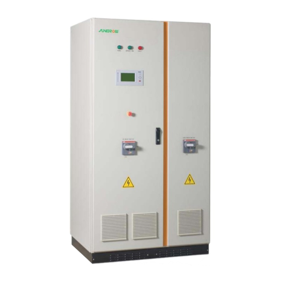
Chapter 2 provides basic information about SG100K3. 2.1. Basic Structure and Appearance SG100K3 is an advanced and reliable three-phase grid connected inverter for solar power generation system with a rating of 100KW. The SG100K3 inverter utilizes the advanced power conversion technology with the... -
Page 15: Figure 2-2 Simple Circuit Diagram Of Sg100K3
Figure 2-2 Simple circuit diagram of SG100K3... -
Page 16: Main Technical Specifications
2 2 .2. Main Technical Specifications The SG100K3 can only perform normal operation in case all the specific requirements listed below are met. 2.2.1. Mechanical Data Dimensions (W×H×D) 1020 x 1964 x 770(mm) Weight Approx. 900 Kg Ambient Temperature (Operating) -20 to 55 °C... -
Page 17: Data Acquisition
2 2 .3. Data Acquisition 2.3.1. Data Display The inverter will display real-time and logged running data of the inverter to the equipped LCD interface. 2.3.2. Fault Indication The inverter can record the time and type of all faults in non-volatile memory and inform the fault state to the customers through LCD and LED. -
Page 18: General Requirements
2 2 .4. General Requirements 2.4.1. Grid Requirements The output of SG100K3 is designed to fit the 400V 3-phase-4-wire grid system, which includes L , Neutral and power ground. 2.4.2. Ventilation and Installation Requirements Maintain a minimum of 100 mm clearance in back, 400mm in front and 600mm in top of the SG100K3 for proper ventilation and installation operation. - Page 19 Mechanical Installation Chapter 3 describes the instructions needed for the mechanical installation of SG100K3.
-
Page 20: Mechanical Installation
3.2. Weight and Dimensions Note The Weight of the SG100K3 The SG100K3 inverter weighs approximately 900 Kg. Please take this heavy weight into consideration during shipping and moving. Note The Dimensions of the SG100K3 SG100K3... -
Page 21: Checking The Unit
Please contact Sungrow immediately in case you find any visual damage or lost of the delivery components supposed to be included in the package. -
Page 22: Moving The Unit
3 3 .5. Moving the Unit To move the crate that contains the SG100K3: 1. Place the forks of the forklift to the bottom of wooden crate. 2. Elevate the SG100K3 from beneath the wooden crate. Forklift lifting locations – underneath pallet Figure 3-2 3.6. -
Page 23: Move The Sg100K3 After Unpacking
3 3 .7. Move the SG100K3 after Unpacking Using a forklift to move the SG100K3: 1. Place the forks of the forklift below the unit at the points specified in Figure 3-2. 2. Lift the SG100K3 from beneath the enclosure. -
Page 24: Installation Site
SG100K3 Grid-Connected Photovoltaic Inverter is designed for indoor use only and must be placed to a level concrete floor or pad. Any existing unevenness, depressions or slope must be corrected prior to installation. - Page 25 Electrical Connection Chapter 4 describes the step-by-step procedure for the electrical connections of SG100K3.
-
Page 26: Electrical Connection
4 4 . Electrical Connection Chapter 4 describes the step-by-step electrical connection process needed to complete the installation the SG100K3. Note All wiring methods and processes should be in accordance with Local Electrical Code. 4.1. Wire Specifications The DC input wires (including DC positive and DC negative) must be chosen according to the recommended rating below. -
Page 27: Start Electrical Connections
4 4 .2. Start Electrical Connections Use the following instructions for correct wiring. 4.2.1. Open the Door The SG100K3 is stopped and latched when shipped; users must open the front door of SG100K3 for wiring. Door Lock AC Main Switch... -
Page 28: Figure 4-2 Open The Main Switches
S S tep 1: Switch off both the AC and DC main switches (turn both the switches counter-clockwise). Turn both the switch Counter-clockwise Figure 4-2 Open the main switches Step 2: Press down the doorlock to release the latch handle and turn the handle clockwise. -
Page 29: Figure 4-4 Inside The Sg100K3 Enclosure
Note that there are 4 screws (in the yellow circle) to fix the shield, loose and take down them all. All the input and output wires are connected to the terminals of SG100K3 through the cable entry holes at the bottom of the Enclosure. Screws Screws... -
Page 30: Dc Connections
4 4 .3. DC Connections The DC input copper bus is located in the lower left corner of the inverter; there are 4 DC inputs in the DC copper bus. Wires rated for a minimum of 900V are required for connecting the DC wires to the inputs of the inverter. -
Page 31: Ac Grid Connections
To reduce the risk of fire, connect only to a circuit provided with 250 amperes maximum branch circuit over current protection. Note When connecting external AC wires to the SG100K3, positive phasing sequence must be maintained throughout the installation process 4.4.1. Connection Process 1. -
Page 32: Ground Connections
4 4 .5. Ground Connections 1. Route the Ground wire through the cable entry holes. 2. Then connect the ground wire to the ground copper bar located at the bottom of the inverter, see Figure 4-8 . The cross section of the ground conduction is larger than 10mm The ground copper bus-bar Figure 4-8 Ground wire routing Warning... -
Page 33: Communication Connection
3. Secure the wires are tightened. 4. Connect the RS485/232 converter DB9 to the PC DB9 serial port. PIN3:TXD PIN2:RXD RS485A TX+/RX+ 5 4 3 9 8 7 6 RS485B TX-/RX- RS485/232 Converter PC RS232 Port SG100K3 Figure 4-10 Serial communication interface connection... - Page 34 Commissioning Chapter 5 describes the verification and commissioning of SG100K3.
-
Page 35: Commissioning
5 5 . Commissioning Chapter 3 describes the procedures needed to verify whether your installation of the SG100K3 is correct and how to start the inverter for the first time. 5.1. Visual Inspection To perform a visual inspection of theSG100K3: 1. -
Page 36: How To Restart The Inverter After Using The Emergency Stop Button
5.3. How to Restart the Inverter after Using the Emergency Stop Button Users must manually restart the inverter according to the following procedure when the operation of the SG100K3 is stopped by punching the emergency stop button: 1. Turn the emergency stop button clockwise to release the inverter from the stop state. - Page 37 Appendix...
-
Page 38: Appendix A: Technical Data
6 6 . Appendix A: Technical Data The following tables list the technical data of the SG100K3. Basic production information and performance of the SG100K3 are available from these tables. 6.1. DC Parameters Max. DC Power 110kWp MPPT DC Voltage Range 450V to 820V Max. -
Page 39: Mechanical Parameters
6 6 .4. Mechanical Parameters Dimensions(W×H×D) 1020 x 1964 x 770mm Weight 900kg Mounting Placed on the floor 6.5. Environmental Parameters Environmental category Indoor, conditioned Pollution Degree Wet Location Ingress Protection IP20 Ambient Temperature -20°C ~ 55°C Relative Humidity (Non condensing) <95% 6.6. -
Page 40: Exclusion Of Liability
7 7 . Appendix B 7.1. Exclusion of Liability The content of these documents is periodically checked and revised, when necessary, please call us or check our website for the latest www.sungrowpower.com information. However discrepancies cannot be excluded. No guarantee is made for the completeness of these documents. -
Page 41: About Us
The power rating of Sungrow products covers from several hundred watt to large mega-watt systems. The pursuit of Sungrow is to help our customers acquire stable and clean power with minimum cost, maximum reliability and enhanced safety. Trademarks is a registered trademark of Sungrow Power Supply Co.,Ltd.
Need help?
Do you have a question about the SG100K3 and is the answer not in the manual?
Questions and answers