Table of Contents
Advertisement
Advertisement
Table of Contents
Troubleshooting

Subscribe to Our Youtube Channel
Related Manuals for Sungrow SG1K5TL


Summary of Contents for Sungrow SG1K5TL
- Page 2 About This Manual Thank you for purchasing inverter SG1K5TL from Sungrow. We hope that the device will meet your satisfaction when you use it with your PV plant system. The purpose of this manual is to provide detailed product information and instructions for use of SG1K5TL PV grid-connected inverter.
- Page 3 Symbols Explanation Important instructions contained in this manual should be followed during installation, operation and maintenance of the inverter. And they will be highlighted by these symbols. DANGER indicates a hazard with a high level of risk which, if not avoided, will result in death or serious injury.
-
Page 4: Table Of Contents
Contents SAFETY AND PRODUCT INFORMATION ..............1 1 Safety Instructions ....................3 2 Product Introduction....................7 2.1 Intended Usage ..........................8 2.2 Circuit Description..........................9 2.3 Product Description ........................10 2.3.1 Product Appearance....................... 10 2.3.2 Dimensions and Weight of Inverter ..................11 2.3.3 LCD Display Panel ......................... 12 INSTALLATION AND MAINTENANCE INFORMATION ........ - Page 5 5.6.2 Assembling AC Cables to Connector ..................33 5.6.3 AC Wiring Procedure......................34 5.7 Grounding of Inverter........................35 5.8 Connecting Communication Cable ....................36 5.8.1 Monitoring System........................36 5.8.2 Connecting RS485 Cable....................... 37 6 Commissioning ..................... 39 6.1 Verify before Commissioning ......................40 6.2 Commissioning Procedure......................
-
Page 6: Safety And Product Information
SAFETY AND PRODUCT INFORMATION For Installer and User 1 ... - Page 7 2 ...
-
Page 8: Safety Instructions
Safety Instructions About This Chapter This chapter provides crucial safety instructions about SG1K5TL. Please read this chapter carefully before any work with the inverter. 3 ... - Page 9 User Manual IMPORTANT SAFETY INSTRUCTIONS SAVE THESE INSTRUCTIONS SG1K5TL inverter is designed and tested according to international safety requirements. But as all electrical and electronic equipments, certain precautions should be observed during installing, operating and maintaining. Incorrect operation or work performed incorrectly can result in damage to:...
- Page 10 Safety Instructions Only after receiving prior approval from the utility company and qualified personnel installing the inverter, you can connect the inverter to the utility grid. All electrical connections must be in accordance with local and national electrical codes. All cables must be firmly attached, undamaged, properly insulated and adequately dimensioned.
- Page 11 SG1K5TL User Manual Electrostatic discharge can damage the inverter. During replacing or installing the inner components, the technical personnel should take appropriate protective measures such as electrostatic bracelet. Others All safety instructions, warning labels and nameplate on the inverter body:...
-
Page 12: Product Introduction
Product Introduction About This Chapter This chapter provides basic information about inverter SG1K5TL. 7 ... -
Page 13: Intended Usage
SG1K5TL serial inverters are robust, grid-connected, transformer-less and of high conversion efficiency. SG1K5TL inverter transforms the direct current generated by PV arrays into stable alternating current and outputs the AC power into the utility grid. This inverter is a crucial unit in the small-scaled PV power system. -
Page 14: Circuit Description
Product Introduction Circuit Description Fig 2-2 shows the main circuit of SG1K5TL-a transformer-less and grid-connected inverter. Boost circuit raises input DC voltage. And there is a MPP tracker to ensure that maximum power from PV arrays can be utilized. Then a full bridge inverter circuit converts DC power to AC power. -
Page 15: Product Description
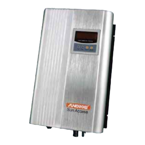
The four waist-shape holes are used for mounting the inverter against the wall. DC terminal Interface between inverter and PV arrays. SG1K5TL: 2 pair Heat sink Cool down the temperature due to heat inside the inverter. AC terminal Standard communication interface. -
Page 16: Dimensions And Weight Of Inverter
Product Introduction 2.3.2 Dimensions and Weight of Inverter Fig 2-4 Dimensions of Inverter Table 2-1 Dimensions Value Type W(mm) H(mm) D(mm) Net weight(kg) SG1K5TL 10.54 11 ... -
Page 17: Lcd Display Panel
SG1K5TL User Manual 2.3.3 LCD Display Panel LCD display panel comprises LED indicators, buttons and LCD screen. Leds indicate the current state of the inverter. The current running information and history information can be shown in the LCD screen via operating the buttons. -
Page 18: Installation And Maintenance Information
INSTALLATION AND MAINTENANCE INFORMATION Only for Installer 13 ... - Page 19 14 ...
-
Page 20: Installation Flow
Installation Flow About This Chapter This chapter demonstrates installation flow from unpacking to successful commissioning. 15 ... - Page 21 SG1K5TL User Manual The following diagram shows the installation flow of inverter for installer. Please follow these procedures. Fig 3-1 Installation Flow Chart Table 3-1 Description of Installation Flow Order Description Remark Unpacking the inverter and inspection Section 4.1 Read this manual, especially the section on “safety instruction”...
-
Page 22: Installing Inverter Onto Wall
Installing Inverter onto Wall About This Chapter This chapter provide information about choose installation site and gives step-by-step procedures to install the inverter onto the wall. And related safety instructions are also included. 17 ... -
Page 23: Unpacking And Inspection
If damage to the packing box is visible, or if you find that the inverter unit is damaged after unpacking, please notify the shipping company and Sungrow. If a related photo is supplied, you will get faster and better service. -
Page 24: Moving Inverter
When choosing the installation site, ensure that there is no electromagnetic interference with other electrical and electronic equipments. The inverter unit SG1K5TL can only be installed indoors. The wall selected should be strong enough to hold the weight of the inverter over a long period of time. - Page 25 SG1K5TL User Manual The ambient temperature of chosen installation site ranges from -25°C to 50°C. Do not install the unit in an enclosure exposed to the direct sunlight. Exposure to the sun may cause additional internal heating, which will result in derating.
-
Page 26: Installation Procedure
Installing Inverter onto Wall Installation Procedure The four waist-shape holes on the heat sink are used as the mounting holes to install the inverter onto the wall. You can drill holes according to its dimensions. Fig 4-2 Dimensions of Heat Sink (unit: mm) In the following pages we will introduce how to install the inverter onto wall via following fasteners. - Page 27 SG1K5TL User Manual INSTALLATION PROCEDURE: In order to avoid electrical shock or other injury, inspect existing electronic or plumbing installations before drilling holes. Step 1: Drill four holes according to dimensions of inverter’s heat sink. Step 2: Clean holes and then insert plastic expansion pipes into the holes.
-
Page 28: Electrical Connection
Electrical Connection About This Chapter This chapter proposes step-by-step procedures to perform electrical connection and related safety instructions. 23 ... -
Page 29: General Safety Instruction
SG1K5TL User Manual General Safety Instruction Improper operation during the wiring process can cause fatal injury to operator or unrecoverable damage to the inverter. Only qualified personnel can perform the wiring work. All electrical installations must be in accordance with local and national electrical codes. -
Page 30: Terminals Description
All electrical terminals are located at the bottom of unit. Fig 5-1 shows the connection area. Enough space should be kept for electrical connection at the bottom of the inverter when choosing the installation site. GRID RS485 Fig 5-1 Terminals Description of SG1K5TL Item Description AC terminal RS485 terminal DC terminals... -
Page 31: Overview Of Electrical Connection
PV arrays There is two pair of input terminals for inverter SG1K5TL. The allowable maximum open-circuit voltage of PV arrays is 450V. SunInfo logger User can order it from Sungrow. -
Page 32: Specifications Of Cables
Electrical Connection Specifications of Cables All cables for PV power system are equipped with water-proof direct plug-in connectors. You‘ll find these connectors in the package. For electrical connection in PV power system, specification of all cables used should meet following requirements. And user should equip these appropriately sized cables. Table 5-1 Specifications of Cables Items Min. -
Page 33: Connecting Inverter To Pv Arrays
SG1K5TL User Manual Connecting Inverter to PV Arrays 5.5.1 Safety As input of the inverter in the PV power system, PV Arrays’ features should be paid attention to. Please refer to PV module’s data sheet. When designing PV arrays, following requirements should be met. -
Page 34: Assembling Dc Cable To Connector
Electrical Connection 5.5.2 Assembling DC Cable to Connector All DC cables are equipped with water-proof direct plug-in connectors, which mate with DC terminals at the bottom of the inverter. The positive and negative connectors are marked with polarity symbols and should be equipped with correctly colored cable. - Page 35 SG1K5TL User Manual DC Negative Connector Assembling Procedure: Step 1: Unscrew the water-proof terminal in the following direction. Step 2: Strip off insulation layer of DC cable and crimp cable core with hand crimping pliers. The length of strip insulation is approximate 8mm.
-
Page 36: Dc Wiring Procedure
PV string. Step 5: Plug DC positive and negative connector into corresponding terminals. If it makes a click sound, it means DC connector has attached to terminals. For inverter SG1K5TL, the acceptable number of PV strings is one. 31 ... -
Page 37: Connecting Inverter To Ac Grid
Grid Frequency 47~51.5Hz/57~61.5Hz The grid connection of inverter SG1K5TL is made via 3 wires (L, N and GND). Feeding power is always single-phase via AC terminal at the bottom of the unit. An appropriately sized AC circuit breaker is suggested as a protection equipment in AC connection, as shown in Fig 5-2. -
Page 38: Assembling Ac Cables To Connector
Electrical Connection 5.6.2 Assembling AC Cables to Connector Inverter is equipped with water-proof direct plug-in connectors for AC connection, which mate with AC terminals at the bottom of the inverter. “L”, “N” and “GND” should be equipped with correctly colored cables for distinguishing. Please refer to related standards about wiring color. -
Page 39: Ac Wiring Procedure
SG1K5TL User Manual Step 5: Pull cables outwards to confirm whether they are installed firmly. Step 6: Tighten the cable gland in opposite direction. If the recess on the front-end part of AC connector to match perfectly with the AC terminal of the inverter, the connection of all AC cables is correct. -
Page 40: Grounding Of Inverter
Electrical Connection Grounding of Inverter Because of the transform-less design of the inverter, DC positive pole and DC negative pole are not permitted to be grounded. Otherwise the inverter can stop running. All non-current carrying exposed metal parts of equipment and other enclosure in the PV power system should be grounded (e.g., PV arrays, DC circuit breaker and inverter). -
Page 41: Connecting Communication Cable
SG1K5TL User Manual Connecting Communication Cable 5.8.1 Monitoring System The inverter provides RS485 interface to communicate with remote PC or logger. User can monitor the state of the inverter and observe current running information and history record via this interface. -
Page 42: Connecting Rs485 Cable
Shielding layer of RS485 bus should be single-point grounding SunInfo logger and RS485-232 converter are optional devices and can be ordered from Sungrow. Data logger Wiring procedure: Step 1: A resistance with 120Ω is connected at the initiating terminal of RS485 bus. - Page 43 SG1K5TL User Manual Wiring procedure: Step 1: A resistance with 120Ω is connected at the initiating terminal of RS485 bus. Step 2: Plug the connector of RS485 cable into corresponding RS485 terminal of Inverter 1. Step 3: The two lines of the other end of RS485 cable, labeled A and B, are connected to corresponding lines of RS485 bus, as the above diagram.
-
Page 44: Commissioning
Commissioning About This Chapter This chapter demonstrates how to check before commissioning and operation procedures. 39 ... -
Page 45: Verify Before Commissioning
SG1K5TL User Manual Verify before Commissioning Num Item Remark Verify whether inverter is fastened onto the wall. See “4 Installing Inverter onto Wall”. Check whether all cables are undamaged, See” 5.4 Specifications of Cables”. properly insulated and adequately dimensioned. Check whether all cables are firmly attached and See “5.5 Connecting Inverter to PV... -
Page 46: Troubleshooting
Troubleshooting About This Chapter This chapter illustrates troubleshooting of LED indicator and malfunction displayed in LCD screen. 41 ... -
Page 47: Troubleshooting Of Led Indicator
Electrical Connection”. 4. Check whether the voltage of DC input exceeds start-up voltage of inverter. 5. If all above conditions are OK, please contact Sungrow. “Fault” indicator is lit 1. There is a fault which is not removed yet. 2. Perform troubleshooting in according to fault type in LCD screen. See “7.2 Troubleshooting of Faults in LCD Screen”. -
Page 48: Troubleshooting Of Faults In Lcd Screen
5. Close DC circuit breaker. 6. Close AC circuit breaker. 7. If the fault can not be solved, please contact Sungrow. PM-FAULT If this malfunction occurs, the reasons are very complicated. - Page 49 2. Otherwise perform the command “Stop”. 3. Perform the command “Start” to restart the inverter. 4. If this malfunction still exists, please contact Sungrow. If you have any problems in operating on the inverter, please contact us: Telephone: +86 551 532 7834/532 7845 Email: info@sungrow.cn...
-
Page 50: Operation Information
OPERATION INFORMATION For User and Installer 45 ... - Page 51 46 ...
-
Page 52: Operation Of Lcd Menu
Operation of LCD Menu About This Chapter This chapter shows operation of LCD menu via button to check the record in the inverter and configure the parameters of the inverter. 47 ... -
Page 53: Button Function
SG1K5TL User Manual Button Function Inverter offers two buttons for user to look up running information and configure parameters. And the two buttons are reusing ones. User should know the button operation and function before any operation onto inverter. Table 8-1 Description of Button Function... -
Page 54: Operation Mode Of Inverter
Operation of LCD Menu Operation Mode of Inverter There are three modes for inverter SG1K5TL. After being energized, the inverter tracks the PV arrays’ maximum power point (MPP) and converts DC power to AC power. Fault If a fault occurs during operation, the inverter will automatically stop operation, trigger AC relay and display the fault type in the LCD panel with the “Fault”... -
Page 55: Overview Of Lcd Menu
SG1K5TL User Manual Overview of LCD Menu ▼ ▼ ▼ ▼ ▼ ▼ ▼ ▼ ▼ Fig 8-1 Menu Tree-English 50 ... -
Page 56: Start-Up Menu
This menu includes 2 separate pages. The first screen includes parameters of “E-today” and “P-ac”. “E-today” indicates the daily output energy generated by SG1K5TL in the unit of kWh. “P-ac” indicates the real time output power of SG1K5TL in the unit of kW. -
Page 57: Main Control Menu
SG1K5TL User Manual Main Control Menu This menu contains running information-“Run-inform”, fault record-“Fault-record”, start/stop command of the inverter-“Start/Stop” and parameters setting-“Set-param”. Users can short press “ESC/▼” button to make the arrow pointed to selected menu. Check Run-inform In order to check run information of inverter, you can access “Current-inform” and “Total-inform”... - Page 58 Operation of LCD Menu Table 8-3 Electrical Real Time Data (Current-inform) Data name Explanation Unit V-grid Grid voltage I-grid Output AC current F-grid Grid frequency V-dc DC Voltage (of PV array) I-dc DC Current (of PV array) P-ac Output AC power E-today Energy generated today E-month...
-
Page 59: Check Fault-Record
The “Fault-record” menu displays the latest fault records, which includes fault type (see Table 8-5), fault occurring time, fault parameter and fault record number. Inverter SG1K5TL can store at most 20 fault records. The latest fault record number is always 01. The oldest fault record number is always 20(suppose there are 20 fault records). -
Page 60: Start And Stop Inverter
Operation of LCD Menu Start and Stop Inverter If input and output conditions meet the related requests, inverter will work automatically. And if input and output conditions fail, inverter will stop automatically. If you want start and stop inverter manually, you can operate as the following picture. Start through LCD If you want to restart inverter after LCD “stop”... -
Page 61: Set Parameters For Inverter
Power-adj ▼ Long press“ESC/▼” Load-default Inverter SG1K5TL supports two languages: Chinese and English. You can select your language as the following picture. 8.10.2 Adjust Time Displayed in Inverter If “time” displayed in inverter is not in accordance with your local time, you should perform the following operation. -
Page 62: Firmware
Operation of LCD Menu The date format is year/month/date. The time format is hour/minute/second. Clock is 24-hour format. 8.10.3 Firmware User can not set this parameter. 8.10.4 Set Power-adj If “E-total” value deviates from the value in metering device, you should set the parameter “power-adj”. -
Page 63: Set Run Parameter
SG1K5TL User Manual 8.10.6 Set Run Parameter There is not run parameter for setting. If you perform “Run-param” operation, LCD just displays “No Run-param”. 8.10.7 Set Protective Parameters Protective parameters include “Vgrid-max”, “Vgrid-min”, “Fgrid-max” and “Fgrid-min”. If actual condition exceeds these setting value, inverter will stop running and display corresponding fault. -
Page 64: Set Communication Parameters
Operation of LCD Menu 8.10.8 Set Communication Parameters If there is more than one inverter to be monitored, you should set appropriate address and baud rate for each inverter. Each inverter should have different address and have same baud rate to ensure good communication. - Page 65 SG1K5TL User Manual 60 ...
-
Page 66: Appendix
APPENDIX Technical Data Input Data Max. DC Voltage 450Vdc Start Voltage 170V MPP Voltage Range 150V~380V Min. DC Voltage 150V Max. DC Power 1700W Max. Input Current Number of MPPT Trackers/Strings Per MPP Tracker Output Data Rated output power 1500W Max. - Page 67 SG1K5TL User Manual Protection Degree IP20(indoor) Power Comsumption at Night Operating Temperature -25℃~+50℃ Relative Humidity 0~95%,non-condensing Cooling method natural cooling Max. Altitude 2000m Display and Communication Display Standard Communication Interface RS485 Optional Communication Interface Ethernet Mechanical Data 288mm*438mm*126mm Dimensions(W*H*D) Net weight 10.54kg...
-
Page 68: Exclusion Of Liability
In case of unforeseen calamity or force majeure The use of supplied software produced by Sungrow Power Supply Co., Ltd. is subject to the following conditions: Sungrow Power Supply Co., Ltd. rejects any liability for direct or indirect damages arising from the use of the SunInfo software. -
Page 69: About Us
The power rating of Sungrow products covers from several hundred watt to large mega-watt systems. The pursuit of Sungrow is to help our customers acquire stable and clean power with minimum cost, maximum reliability and enhanced safety.
Need help?
Do you have a question about the SG1K5TL and is the answer not in the manual?
Questions and answers