Advertisement
Quick Links
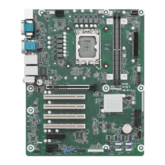
IMB-1713
The terms HDMI
®
and HDMI High-Definition
Multimedia Interface, and the HDMI logo are
trademarks or registered trademarks of HDMI
Licensing LLC in the United States and other
countries.
Revision History
Date
Description
January 4, 2023
First Release
COM Port Pin9 PWR Setting Jumpers
33 : PWR_COM1 (For COM Port1)
PWR_COM2 (For COM Port2)
17 : PWR_COM3 (For COM Port3)
PWR_COM4 (For COM Port4)
PWR_COM5 (For COM Port5)
PWR_COM6 (For COM Port6)
1-2 : +5V
2-3 : +12V
Chassis FAN Connectors (+12V)
1 : CHA_FAN1
GND
+12V
CHA_FAN_SPEED
FAN_SPEED_CONTROL
9 : CHA_FAN2
GND
+12V
CHA_FAN_SPEED
FAN_SPEED_CONTROL
3 : CHA_FAN3
FAN_SPEED_CONTROL
CHA_FAN_SPEED
2 : ATX 12V Power Connector
4 : M.2 Key-M Socket (M2_M1)
Pin
Signal Name
2
4
6
1
8
2
10
12
14
16
18
20
22
24
26
28
30
32
34
36
38
40
42
SMB_DATA
44
46
48
57
58
50
52
54
67
56
68
58
74
68
75
70
72
74
Jumpers and Headers Setting Guide
35
CHA_FAN1
34
1
PWR_COM1
33
PWR_COM2
32
1
LAN_LED2
1
1
LAN_LED1
31
USB 3.2 Gen2
Top:
T: USB3_2
LAN2
B: USB3_1
USB 2.0
30
Top:
T: USB2_6
LAN1
B: USB2_5
29
28
DACC1
27
1
BUZZ2
26
1
SPDIF1
1
PCIE3
HD_AUDIO1
25 24
5 : CPU FAN Connector (+12V)
6 : USB 2.0 Connector (USB2_9)
7 : PWR LOSS Jumper (PWR_LOSS1)
Open : No Power Loss
Short : Power Loss
8 : 24-pin ATX Power Input Connector
12
24
1
13
10 : USB 3.2 Gen1 Header (USB3_3_4)
Vbus
IntA_P0_SSRX-
IntA_P0_SSRX+
GND
+12V
IntA_P0_SSTX-
IntA_P0_SSTX+
GND
GND
IntA_P0_D-
IntA_P0_D+
8
5
11 : SATA3 Connectors (SATA3_1 ~ SATA3_4)
4
1
12 : 5-pin Thunderbolt AIC Connector (TB1)
1
PIN
Signal Name
Pin
1
+3.3V
GND
1
+3.3V
GND
3
2
NA
NA
5
NA
NA
7
3
LED
GND
9
+3.3V
NA
11
4
+3.3V
NA
13
+3.3V
GND
15
5
+3.3V
NA
17
NA
NA
19
NA
GND
21
13 : Clear CMOS Headers
NA
NA
23
NA
NA
25
CLRMOS1 :
NA
GND
27
NA
NA
29
NA
NA
31
1-2 : Normal
NA
GND
33
NA
NA
35
NA
NA
37
2-3 : Clear CMOS
SMB_CLK
GND
39
PERn0
41
CLRMOS2 :
NA
PERp0
43
NA
GND
45
NA
PETn0
47
Open : Normal
PERST#
PETP0
49
CLKREQ#
GND
51
NA
PEFCLKn
53
Short : Auto Clear CMOS (Power Off)
NA
PEFCLKp
55
NA
GND
57
Mechanical Key
NA
NA
67
+3.3V
PEDET
69
+3.3V
GND
71
+3.3V
GND
73
GND
75
1
2
3 4
5
1
1
CHA_FAN3
1
CPU_FAN1
1
IMB-1713
PCIE1
PCI1
PCI2
PCI3
PCI4
PCIE2
COM3
JGPIO_SET1
PWR_COM4
CI2
USB2_7_8
LPT_GPIO1
1
ESPI1
PLED PWRBTN
1
1
1
1
1
1
1
1
HDLED RESET
JGPIO_PWR1
CI1
SIO_AT1
PANEL1
23
22 21
20
19
18
17 16
15
FAN_SPEED_CONTROL
CPU_FAN_SPEED
Vbus
Vbus
IntA_P1_SSRX-
IntA_P1_SSRX+
GND
IntA_P1_SSTX-
IntA_P1_SSTX+
GND
IntA_P1_D-
IntA_P1_D+
ID
1
Signal Name
TB_FRC_PWR
TBCIO_PLUG_EVENT_R2
SLP_S3#
TBT_SLP_S5_S4#
GND
6
7
USB2_9
1
PWR_LOSS1
8
1
9
10
1
Industrial
BIOS
ROM
11
CMOS
Battery
1
12
CLRMOS2
1
PWR_COM3
PWR_COM5
1
1
1
CLRMOS1
13
1
1
COM5
14
PWR_COM6
1
1
1
1
COM4
COM6
14 : COM Port Headers (COM3~6) (RS232)
+12V
GND
15 : ATX/AT Mode Jumper (SIO_AT1)
Open : ATX Mode
Short : AT Mode
16 : Chassis Intrusion Headers (CI1, CI2)
CI2 :
Open : Active Case Open
Short : Normal
CI1 :
Open : Normal
Short : Active Case Open
18 : Printer Port / GPIO Header (LPT_GPIO1)
Printer Port:
* If you want to use the printer port function, please short pin4 and pin5 on
Digital Input / Output Power Select (JGPIO_PWR1).
19 : ESPI Header
1
GND
Signal
GPIO:
PIN Signal Name PIN
Signal Name
26
NC
25
NA
24
GND
23
SIO_GP70/GPP_E6
22
GND
21
SIO_GP71/GPP_E5
20
GND
19
SIO_GP72/TIME_SYNC1
18
GND
17
SIO_GP87/TIME_SYNC0
16
GND
15
SIO_GP86
14
GND
13
SIO_GP85
12
JGPIOPWR
11
SIO_GP84
10
JGPIOPWR
9
SIO_GP83
8
SIO_GP73
7
SIO_GP82
6
SIO_GP74
5
SIO_GP81
4
SIO_GP75
3
SIO_GP80
2
SIO_GP76
1
SIO_GP77
Advertisement

Subscribe to Our Youtube Channel
Related Manuals for ASRock Industrial IMB-1713


Summary of Contents for ASRock Industrial IMB-1713
- Page 1 Jumpers and Headers Setting Guide IMB-1713 CHA_FAN3 CHA_FAN1 USB2_9 CPU_FAN1 PWR_LOSS1 The terms HDMI ® and HDMI High-Definition PWR_COM1 Multimedia Interface, and the HDMI logo are trademarks or registered trademarks of HDMI Licensing LLC in the United States and other PWR_COM2 countries.
- Page 2 B: USB2_5 * Do not apply force to the actuator cover after ic inserted. * Do not apply force to actuator cover when it is opening over 120 degree, Otherwise, the actuator cover may be broken. IMB-1713 PCIE1 Industrial PCI1...
Need help?
Do you have a question about the IMB-1713 and is the answer not in the manual?
Questions and answers