
Subscribe to Our Youtube Channel
Related Manuals for ASRock Industrial IMB-1711


Summary of Contents for ASRock Industrial IMB-1711
- Page 1 IMB-1711 IMB-X1711 User Manual Version 1.0 Published June 2020 Copyright©2020 ASRockInd INC. All rights reserved.
- Page 2 Version 1.0 Published June 2020 Copyright©2020 ASRockInd INC. All rights reserved. Copyright Notice: No part of this documentation may be reproduced, transcribed, transmitted, or translated in any language, in any form or by any means, except duplication of documentation by the purchaser for backup purpose, without written consent of ASRockInd Inc.
- Page 3 The terms HDMI® and HDMI High-Definition Multimedia Interface, and the HDMI logo are trademarks or registered trademarks of HDMI Licensing LLC in the United States and other countries. CAUTION: RISK OF EXPLOSION IF BATTERY IS REPLACED BY AN INCORRECT TYPE. DISPOSE OF USED BATTERIES ACCORDING TO THE INSTRUCTIONS.
-
Page 4: Table Of Contents
Contents 1 Introduction ............5 1.1 Package Contents ............5 1.2 Specifications ..............6 1.3 Motherboard Layout ............9 1.4 I/O Panel ................ 11 2 Installation ............13 2.1 Screw Holes ..............13 2.2 Pre-installation Precautions ........... 13 2.3 Installation of Memory Modules (DIMM) ......14 2.4 Expansion Slots ............ -
Page 5: Introduction
Chapter 1: Introduction Thank you for purchasing ASRockInd IMB-1711 / IMB-X1711 motherboard, a reli- able motherboard produced under ASRockInd’s consistently stringent quality con- trol. It delivers excellent performance with robust design conforming to ASRockInd’s commitment to quality and endurance. In this manual, chapter 1 and 2 contain introduction of the motherboard and step- by-step guide to the hardware installation. -
Page 6: Specifications
1.2 Specifications Form Dimensions ATX (12-in x 9.6-in) Factor ® Intel Gen (Cometlake-S) Core™ Processors, up to 125 W Processor ® Chipset Intel Q470E System Socket LGA1200 BIOS AMI SPI 256 Mbit 3 x PCIe Gen3 Slots (PCIE1 / PCIE2 / PCIE3: Single at x16 (PCIE1);... - Page 7 Realtek ALC887/ALC897 HD, High Audio Interface Definition Audio. Line-out, Mic-in. ® LAN1: Intel I225LM with 10/100/1000/2500 Controller/ Mbps Ethernet ® Speed LAN2: Intel I219LM with 10/100/1000 Mbps, support AMT / vPro Connector 2 x RJ-45 HDMI 1 x HDMI 2.0a DisplayPort 1 x DP 1.2 Ethernet 1 x 1 Gigabit LAN, 1 x 2.5 Gigabit LAN...
- Page 8 Operating 0ºC ~ 60ºC Temp Storage -40°C ~ 85°C Temp Environment Operating 5% ~ 90% Humidity Storage 5% ~ 90% Humidity...
-
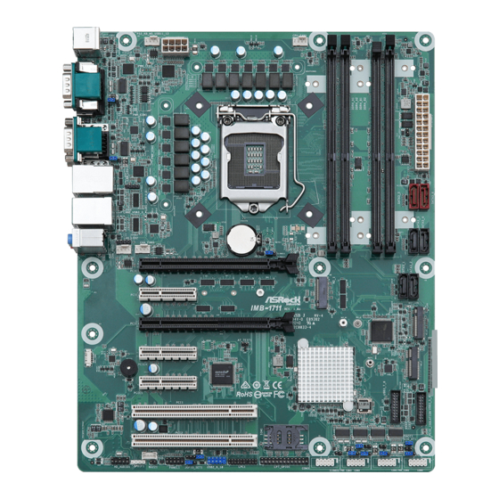
Page 9: Motherboard Layout
1.3 Motherboard Layout... - Page 10 1 : Chassis FAN Connectors (+12V) (CHA_FAN1~3) 2 : ATX 12V Power Connector 3 : CPU FAN Connector (+12V) 4 : PWR LOSS Jumper (PWR_LOSS1) 5 : 24-pin ATX Power Input Connector 6 : SATA3 Connectors (SATA3_1 ~ SATA3_6) 7 : M.2 Key-M Socket (M2_1) 8 : M.2 Key-B Socket (M2_B1) 9 : M.2 Key-E Socket (M2_2) 10 : USB 3.2 Gen1 Headers (USB3_5_6, USB3_7_8)
-
Page 11: I/O Panel
1.4 I/O Panel USB 2.0 Ports (USB11_12) Microphone (Pink) COM Port (COM1) (RS232/422/485)* USB 3.2 Gen2 Ports (USB3_3_4) COM Port (COM2) (RS232/422/485)* USB 3.2 Gen1 Ports (USB3_1_2) LAN RJ-45 Port (LAN1)** D-Sub Port (VGA1) LAN RJ-45 Port (LAN2)*** DisplayPort (DP1) Line In (Light Blue) HDMI Port (HDMI1) Line Out (Lime) - Page 12 *** There are two LED next to the LAN port. Please refer to the table below for the LAN port LED indications. LAN Port LED Indications ACT/LINK SPEED Activity/Link LED SPEED LED Status Description Status Description No Link 10Mbps connection Blinking Data Activity Orange 100Mbps connection...
-
Page 13: Installation
Chapter 2: Installation This is an ATX form factor (12” x 9.6”) motherboard. Before you install the mother- board, study the configuration of your chassis to ensure that the motherboard fits into it. Make sure to unplug the power cord before installing or removing the motherboard. -
Page 14: Installation Of Memory Modules (Dimm)
2.3 Installation of Memory Modules (DIMM) This motherboard provides four 288-pin DDR4 (Double Data Rate 4) DIMM slots, and supports Dual Channel Memory Technology. 1. For dual channel configuration, you always need to install identical (the same brand, speed, size and chip-type) DDR4 DIMM pairs. 2. -
Page 16: Expansion Slots
2.4 Expansion Slots There are 5 PCI Express slots, 2 PCI slots, 3 M.2 sockets and 1 SIM socket on this motherboard. PCIE slots: PCIE1 (PCIE 3.0 x16 slot) is used for PCI Express x16 lane width cards. PCIE2 (PCIE 3.0 x4 slot) is used for PCI Express x4 lane width cards. PCIE3 (PCIE 3.0 x16 slot) is used for PCI Express x8 lane width cards. - Page 17 M.2 sockets: 1 x M.2 (Key E, 2230) with PCIe x1, USB 2.0 and CNVi for Wireless. 1 x M.2 (Key B, 3042 / 3052) with PCIe x1 / USB 3.0 / USB 2.0 and SIM socket for 4G / 5G. 1 x M.2 (Key M, 2242 / 2260 / 2280) with SATA3 and PCIe x4 for SSD.
-
Page 18: Jumpers Setup
2.5 Jumpers Setup The illustration shows how jumpers are setup. When the jumper cap is placed on pins, the jumper is “Short”. If no jumper cap is placed on pins, the jumper is “Open”. The illustration shows a 3-pin jumper whose pin1 and pin2 are “Short”... - Page 19 COM Port Pin9 PWR Setting Jumpers 1-2 : +5V 2-3 : +12V (3-pin PWR_COM1, 2 (For COM Port1, 2)) (see p.9, No. 32) (3-pin PWR_COM3~6 (For COM Port3~6)) (see p.9, No. 15) PWR LOSS Header Short : Power Loss Open : no Power Loss (2-pin PWR_LOSS1) (see p.9, No.
- Page 20 DACC1 Short : ACC Open : no ACC (2-pin DACC1) (see p.9, No. 13)
-
Page 21: Onboard Headers And Connectors
2.6 Onboard Headers and Connectors Onboard headers and connectors are NOT jumpers. Do NOT place jumper caps over these headers and connectors. Placing jumper caps over the headers and connectors will cause permanent damage of the motherboard! CPU Fan Connector (+12V) Please connect the CPU fan 4 3 2 1 cable to the connector and... - Page 22 RESET (Reset Switch): Connect to the reset switch on the chassis front panel. Press the reset switch to restart the computer if the computer freezes and fails to perform a normal restart. PLED (System Power LED): Connect to the power status indicator on the chassis front panel. The LED is on when the system is operating.
- Page 23 USB 3.2 Gen1 Headers There are two headers on this Vbus Vbus Vbus IntA_P1_SSRX- motherboard. Each header can IntA_P0_SSRX- IntA_P1_SSRX+ (19-pin USB3_5_6, see p.9, No. 10) IntA_P0_SSRX+ IntA_P1_SSTX- support two ports. IntA_P0_SSTX- IntA_P1_SSTX+ IntA_P0_SSTX+ IntA_P1_D- IntA_P0_D- IntA_P1_D+ IntA_P0_D+ (19-pin USB3_7_8, see p.9, No. 10) Dummy IntA_PA_D+ IntA_PB_D+...
- Page 24 Printer Port / GPIO Header (25-pin LPT_GPIO1) (see p.9 No. 18) Printer Port: GPIO: PIN Signal Name PIN Signal Name SIO_GP70 SIO_GP71 SIO_GP72 SIO_GP87 SIO_GP86 SIO_GP85 JGPIOPWR SIO_GP84 JGPIOPWR SIO_GP83 SIO_GP73 SIO_GP82 SIO_GP74 SIO_GP81 SIO_GP75 SIO_GP80 SIO_GP76 SIO_GP77 * If you want to use the printer port function, please short pin4 and pin5 on Digital Input / Output Power Select (JGPIO_PWR1).
- Page 25 SMBUS_TEST1 (4-pin SMBUS_TEST1) (see p.9, No. 25) Signal Signal Signal PIN Signal Name PIN Name Name Name SMB_CLK SMB_DATA Buzzer (2-pin BUZZ1) (see p.9, No. 24)
-
Page 26: Installation Of Rom Socket
2.7 Installation of ROM Socket * Do not apply force to the actuator cover after ic inserted. * Do not apply force to actuator cover when it is opening over 120 degree, Otherwise, the actuator cover may be broken. * The yellow dot (Pin1) on the ROM must be installed at pin1 position of the socket (white arrow area). -
Page 27: Uefi Setup Utility
Chapter 3: UEFI SETUP UTILITY 3.1 Introduction This section explains how to use the UEFI SETUP UTILITY to configure your system. The UEFI chip on the motherboard stores the UEFI SETUP UTILITY. You may run the UEFI SETUP UTILITY when you start up the computer. Please press <F2>... -
Page 28: Navigation Keys
3.1.2 Navigation Keys Please check the following table for the function description of each navigation key. Navigation Key(s) Function Description Moves cursor left or right to select Screens Moves cursor up or down to select items + / - To change option for the selected items <Enter>... -
Page 29: Advanced Screen
3.3 Advanced Screen In this section, you may set the configurations for the following items: CPU Configu- ration, Chipset Configuration, Storage Configuration, Super IO Configuration, AMT Configuration, ACPI Configuration, USB Configuration and Trusted Computing. Setting wrong values in this section may cause the system to malfunction. -
Page 30: Cpu Configuration
3.3.1 CPU Configuration Intel Hyper Threading Technology Intel Hyper Threading Technology allows multiple threads to run on each core, so that the overall performance on threaded software is improved. Active Processor Cores Select the number of cores to enable in each processor package. CPU C States Support Enable CPU C States Support for power saving. - Page 31 Intel Turbo Boost Technology Use this item to enable or disable Intel Turbo Boost Mode Technology. Turbo Boost Mode allows processor cores to run faster than marked fre- quency in specific conditions. The default value is [Enabled]. CPU Thermal Throttling You may select [Enabled] to enable CPU internal thermal control mechanism to keep the CPU from overheating.
-
Page 32: Chipset Configuration
3.3.2 Chipset Configuration Primary Graphics Adapter This allows you to select [Onboard] or [PCI Express] as the boot graphic adapter priority. The default value is [PCI Express]. Above 4G Decoding Enable or disable 64bit capable Devices to be decoded in Above 4G Ad- dress Space (only if the system supports 64 bit PCI decoding). - Page 33 Onboard LAN2 This allows you to enable or disable the Onboard LAN2 feature. Onboard HD Audio Select [Enabled] or [Disabled] for the onboard HD Audio feature. Deep Sleep Mobile platforms support Deep S4/S5 in DC only and desktop platforms support Deep S4/S5 in AC only. The default value is [Disabled]. Restore on AC/Power Loss Select the power state after a power failure.
-
Page 34: Storage Configuration
3.3.3 Storage Configuration SATA Controller(s) Use this item to enable or disable the SATA Controller feature. SATA Mode Selection Use this to select SATA mode. The default value is [AHCI Mode]. AHCI (Advanced Host Controller Interface) supports NCQ and other new features that will improve SATA disk perfor- mance. -
Page 35: Super Io Configuration
3.3.4 Super IO Configuration COM1 Use this to set parameters of COM1. Type Select Use this to select COM1 port type: [RS232], [RS422] or [RS485]. COM2 Use this to set parameters of COM2. Type Select Use this to select COM2 port type: [RS232], [RS422] or [RS485]. COM3 Use this to set parameters of COM3. -
Page 36: Amt Configuration
3.3.5 AMT Technology AMT BIOS Features Use this to enable or disable Intel(R) Active Management Technology BIOS Extension. The default is [Enabled]. ASF support Use this to enable or disable Alert Specification Format. The default is [En- abled]. USB Provisioning of AMT Use this to enable or disable AMT USB Provisioning. - Page 37 WatchDog Use this to enable or disable AMT WatchDog Timer. The default is [Dis- abled]. Activate Remote Assistance Process Trigger CIRA boot. The default is [Disabled]. PET Progress User can enable or disable PET Events progress to receive PET events or not.
-
Page 38: Acpi Configuration
3.3.6 ACPI Configuration Suspend to RAM Use this item to select whether to auto-detect or disable the Suspend-to- RAM feature. Select [Auto] will enable this feature if the OS supports it. PCIE Devices Power On Use this item to enable or disable PCIE devices to turn on the system from the power-soft-off mode. -
Page 39: Usb Configuration
3.3.7 USB Configuration Legacy USB Support Use this option to select legacy support for USB devices. There are two configuration options: [Enabled] and [UEFI Setup Only]. The default value is [Enabled]. Please refer to below descriptions for the details of these two options: [Enabled] - Enables support for legacy USB. -
Page 40: Trusted Computing
3.3.8 Trusted Computing Security Device Support Enable or disable BIOS support for security device. -
Page 41: Hardware Health Event Monitoring Screen
3.4 Hardware Health Event Monitoring Screen In this section, it allows you to monitor the status of the hardware on your system, including the parameters of the CPU temperature, motherboard temperature, CPU fan speed, chassis fan speed, and the critical voltage. CPU_FAN1 Setting This allows you to set CPU fan 1’s speed. -
Page 42: Security Screen
3.5 Security Screen In this section, you may set, change or clear the supervisor/user password for the system. Supervisor Password Set or change the password for the administrator account. Only the ad- ministrator has authority to change the settings in the UEFI Setup Utility. Leave it blank and press enter to remove the password. -
Page 43: Boot Screen
3.6 Boot Screen In this section, it will display the available devices on your system for you to config- ure the boot settings and the boot priority. Boot From Onboard LAN Use this item to enable or disable the Boot From Onboard LAN feature. Setup Prompt Timeout This shows the number of seconds to wait for setup activation key. - Page 44 CSM (Compatibility Support Module) Use this to enable or disable Compatibility Support Module. The default value is [Disabled]. Launch PXE OpROM Policy Select UEFI only to run those that support UEFI option ROM only. Select Legacy only to run those that support legacy option ROM only. Select Do not launch to not execute both legacy and UEFI option ROM.
-
Page 45: Exit Screen
3.7 Exit Screen Save Changes and Exit When you select this option, it will pop-out the following message, “Save configuration changes and exit setup?” Select [OK] to save the changes and exit the UEFI SETUP UTILITY. Discard Changes and Exit When you select this option, it will pop-out the following message, “Discard changes and exit setup?”... -
Page 46: Software Support
Chapter 4: Software Support 4.1 Install Operating System ® ® This motherboard supports various Microsoft Windows operating systems: 10 64- bit. Because motherboard settings and hardware options vary, use the setup proce- dures in this chapter for general reference only. Refer your OS documentation for more information.
Need help?
Do you have a question about the IMB-1711 and is the answer not in the manual?
Questions and answers