
Related Manuals for ASRock Industrial IMB-1234


Summary of Contents for ASRock Industrial IMB-1234
- Page 1 IMB-1234 User Manual Version 1.0 Published February 1, 2023 Copyright©2023 ASRockInd INC. All rights reserved.
- Page 2 Copyright Notice: No part of this documentation may be reproduced, transcribed, transmitted, or translated in any language, in any form or by any means, except duplication of documentation by the purchaser for backup purpose, without written consent of ASRockInd Inc. Products and corporate names appearing in this documentation may or may not be registered trademarks or copyrights of their respective companies, and are used only for identification or explanation and to the owners’...
- Page 3 The terms HDMI® and HDMI High-Definition Multimedia Interface, and the HDMI logo are trademarks or registered trademarks of HDMI Licensing LLC in the United States and other countries. CAUTION: RISK OF EXPLOSION IF BATTERY IS REPLACED BY AN INCORRECT TYPE. DISPOSE OF USED BATTERIES ACCORDING TO THE INSTRUCTIONS.
-
Page 4: Table Of Contents
Contents Chapter 1 Introduction 1.1 Package Contents 1.2 Specifications 1.3 Motherboard Layout 1.4 I/O Panel Chapter 2 Installation 2.1 Screw Holes 2.2 Pre-installation Precautions 2.3 Installation of Memory Modules 2.4 Expansion Slots 2.5 Jumpers Setup Chapter 3 UEFI SETUP UTILITY 3.1 Introduction 3.1.1 Entering BIOS Setup 3.1.2 UEFI Menu Bar... -
Page 5: Chapter 1 Introduction
If you require technical support related to this motherboard, please visit our website for specific information about the model you are using. https://www.asrockind.com/support/index.asp 1.1 Package Contents ASRockInd IMB-1234 Motherboard (Mini-ITX (6.7-in x 6.7-in x 1.5-in, 17.0 cm x 17.0 cm x 3.8 cm)) ASRockInd IMB-1234 Jumper Setting Instruction... -
Page 6: Specifications
1.2 Specifications Mini-ITX (6.7-in x 6.7-in x 1.5-in, 17.0 cm x 17.0 cm Form Factor Dimensions x 3.8 cm) Intel® 12th Gen Alder Lake-P Processors IMB-1234P (i7-1265UE, 2P+8E) Processor IMB-1234M (i5-1245UE, 2P+8E) System IMB-1234V (i3-1215UE, 2P+4E) Chipset BIOS AMI SPI 256 Mbit 1 x M.2 (Key B, 3042/3052) with PCIex1, USB 3.2, USB 2.0 and SIM ofr 4G/5G Expansion... - Page 7 IMB-1234 HDMI 2 x HDMI 2.0 Ethernet 2 x 2.5 Gigabit LAN 2 x USB 2.0 2 x USB 3.2 Gen2 2 x USB 3.2 Gen2 (Type-C, Support DP1.4a display output) Rear I/O * USB4™ Compliance Test is pending for certification.
- Page 8 Operating 0ºC - 60ºC Temp Storage Temp -40ºC - 85ºC Environment Operating 5% - 90% Humidity Storage 5% - 90% Humidity...
-
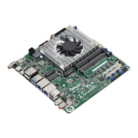
Page 9: Motherboard Layout
IMB-1234 1.3 Motherboard Layout SATA3_1 SATA3_0 DC_JACK1 CPU_FAN1 SATA_PWR1 USB3_3 BLT_PWM2 DC_4PIN1 Thunderbolt Type-C (TC_T1) 8 (*Backside: EDP1) Thunderbolt Type-C (TC_T0) USB 3.2 Gen2 M2_M1 T: USB3_1 B: USB3_2 BIOS M2_E1 LAN1 M2_B1 DDR4_A1 LAN2 DDR4_B1 SIM1 BUZZ1 USB 2.0... - Page 10 1 : 4-pin ATX 12V PWR Connector 2 : USB 3.2 Gen1 Header (USB3_3) 3 : CPU FAN Connector (+12V) 4 : SATA3 Connectors (SATA3_0, SATA3_1) 5 : SATA Power Output Connector 6 : Brightness Control Mode (BLT_PWM2) 7 : Brightness Control Mode (BLT_PWM1) 8 : LVDS Panel Connector* * eDP Connector (on the Backside of PCB) 9 : Backlight Volume Control (BLT_VOL1)
-
Page 11: I/O Panel
IMB-1234 1.4 I/O Panel DC Jack (DC_JACK1) USB 2.0 Port (USB2_3) Thunderbolt Type-C Port (TC_T1) Audio Jack: Green - Line Out Thunderbolt Type-C Port (TC_T0) 10 Audio Jack: Pink - Mic In HDMI Port (HDMI1) 11 USB 2.0 Port (USB2_4) USB 3.2 Gen2 Port (USB3_1) -
Page 12: Chapter 2 Installation
Chapter 2 Installation This is a Mini-ITX (6.7-in x 6.7-in x 1.5-in, 17.0 cm x 17.0 cm x 3.8 cm) form factor motherboard. Before you install the motherboard, study the configuration of your chassis to ensure that the motherboard fits into it. Make sure to unplug the power cord before installing or removing the motherboard. -
Page 13: Installation Of Memory Modules
IMB-1234 2.3 Installation of Memory Modules IMB-1234 provides two 260-pin DDR4 (Double Data Rate 4) SO-DIMM slots, and supports Dual Channel Memory Technology. Step 1. Align a SO-DIMM on the slot such that the notch on the SO-DIMM matches the break on the slot. -
Page 14: Expansion Slots
2.4 Expansion Slots There are 3 M.2 sockets and 1 SIM socket on this motherboard. M.2 sockets: 1 x M.2 (Key B, 3042/3052) with PCIex1, USB 3.2, USB 2.0 and SIM for 4G/5G 1 x M.2 (Key E, 2230) with PCIe, USB 2.0 and CNVi for Wireless 1 x M.2 (Key M, 2242/2260/2280) with PCIe Gen4 x4 for SSD SIM Socket: 1x SIM socket connected to M.2 key B M.2 Key-M Socket... -
Page 15: Jumpers Setup
IMB-1234 2.5 Jumpers Setup The illustration shows how jumpers are setup. When the jumper cap is placed on pins, the jumper is “Short.” If no jumper cap is placed on pins, the jumper is “Open. ” The illustration shows a 3-pin jumper whose pin1 and pin2 are “Short”... - Page 16 COM Port PWR Setting Jumpers 1-2 : +5V 1 2 3 2-3 : +12V (3-pin PWR_COM1~6 (For COM Port1~6)) (see p. 5 , No. 18) Digital Input / Output Default Value Setting 1-2 : Pull-High 2-3 : Pull-Low (3-pin JGPIO_SET1) (see p.
- Page 17 IMB-1234 2.6 Onboard Headers and Connectors Onboard headers and connectors are NOT jumpers. Do NOT place jumper caps over these headers and connectors. Placing jumper caps over the headers and connectors will cause per- manent damage to the motherboard! 4-pin ATX PWR Connector...
- Page 18 SATA3 Connectors SATA3_1 SATA3_0 (SATA3_0, SATA3_1) (see p. 5, No. 4) These two Serial ATA3 (SATA3) connectors support SATA data cables for internal storage devices. The current SATA3 interface allows up to 6.0 Gb/s data transfer rate. SATA3_0 is shared with M2_M1. SATA3_1 is shared with M2_B1. SATA Power Output Connector (4-pin SATA_PWR1) (see p.
- Page 19 IMB-1234 Backlight Volume Control Signal Name (7-pin BLT_VOL1) (see p. 5, No. 9) BLT_DW BLT_UP PWRDN GPIO_VOL_DW GPIO_VOL_UP Inverter Power Control Wafer Signal Name LCD_BLT_VCC (6-pin BLT_PWR1) LCD_BLT_VCC (see p. 5, No. 10) CON_LBKLT_EN CON_LBKLT_CTL eDP Inverter Power Control Wafer...
- Page 20 COM Port Headers (9-pin COM1~6) (see p. 5, No. 15) PIN Signal Name PIN Signal Name PIN Signal Name PIN Signal Name PIN Signal Name DDCD# TTXD RRTS# RRXD DDTR# DDSR# CCTS# This motherboard supports RS232/422/485 on COM1, 2 ports. Please refer to the table below for the pin definition.
- Page 21 IMB-1234 PLED (System Power LED): Connect to the power status indicator on the chassis front panel. The LED is on when the system is operating. The LED keeps blinking when the system is in S1 sleep state. The LED is off when the system is in S3/S4 sleep state or powered off (S5).
- Page 22 ESPI Header (ESPI1) RS232 (20-pin ESPI1) ESPI_ALERT# (see p. 5 , No. 26) Internal Use Internal Use +3VSB ESPI_IO3 ESPI_IO2 ESPI_IO1 ESPI_IO0 SMB_DATA SMB_CLK ESPI_RESET# ESPI_CS# ESPI_CLK Buzzer Header PIN Signal Name PIN Signal Name (2-pin BUZZ2) BUZZ_LOW (see p. 5, No. 27) Battery Connector BAT1 (BAT1)
- Page 23 IMB-1234 SPDIF Header (3-pin SPDIF1) SPDIF OUT (see p. 5 , No. 33) SPDIF header, providing SPDIF audio output to HDMI VGA card, allows the system to connect HDMI Digital TV/projector/LCD devices. Please connect the SPDIF connector of HDMI VGA card to this header.
-
Page 24: Chapter 3 Uefi Setup Utility
Chapter 3 UEFI SETUP UTILITY 3.1 Introduction ASRock Industrial UEFI (Unified Extensible Firmware Interface) is a BIOS utility which offers tweak-friendly options in an advanced viewing interface. The UEFI system works with a USB mouse and offers users a faster, sleeker experience. -
Page 25: Uefi Menu Bar
IMB-1234 3.1.2 UEFI Menu Bar The top of the screen has a menu bar with the following selections: Main For setting system time/date information For advanced system configurations Advanced H/W Monitor Displays current hardware status Security For security settings Boot... -
Page 26: Navigation Keys
3.1.3 Navigation Keys Use < > key or < > key to choose among the selections on the menu bar, and use < > key or < > key to move the cursor up or down to select items, then press <Enter>... -
Page 27: Main Screen
IMB-1234 3.2 Main Screen When you enter the UEFI SETUP UTILITY, the Main screen will appear and display the system overview. Because the UEFI software is constantly being updated, the following UEFI setup screens and descriptions are for reference purpose only, and they may not exactly match what you see on your screen. -
Page 28: Advanced Screen
3.3 Advanced Screen In this section, you may set the configurations for the following items: CPU Configuration, Chipset Configuration, Storage Configuration, Super IO Configura- tion, AMT Configuration, ACPI Configuration, USB Configuration and Trusted Computing. Setting wrong values in this section may cause the system to malfunction. Instant Flash Instant Flash is a UEFI flash utility embedded in Flash ROM. -
Page 29: Cpu Configuration
IMB-1234 3.3.1 CPU Configuration Intel Hyper Threading Technology Intel Hyper Threading Technology allows multiple threads to run on each core, so that the overall performance on threaded software is improved. Configuration options: [Enabled] [Disabled] Active Processor P-Cores This allows you to select the number of cores to enable in each processor package. - Page 30 Intel Virtualization Technology Intel Virtualization Technology allows a platform to run multiple operating systems and applications in independent partitions, so that one computer system can function as multiple virtual systems. Configuration options: [Enabled] [Disabled] Intel SpeedStep Technology Intel SpeedStep technology allows processors to switch between multiple frequen- cies and voltage points for better power saving and heat dissipation.
-
Page 31: Chipset Configuration
IMB-1234 3.3.2 Chipset Configuration VT-d Intel® Virtualization Technology for Directed I/O helps your virtual machine monitor better utilize hardware by improving application compatibility and reliability, and providing additional levels of manageability, security, isolation, and I/O performance. Configuration options: [Enabled] [Disabled]... - Page 32 Active LVDS Use this option to enable or disable the LVDS. The default value is [Disabled]. Set the item to [Enabled]. Then press <F10> to save the setting and restart the system. Now the default value of Active LVDS is changed to ENABLED (F9 load default is also set to ENABLED).
-
Page 33: Storage Configuration
IMB-1234 3.3.3 Storage Configuration VMD Configuration This item allows you to enable or disable the Intel VMD support function. SATA Controller(s) The option allows you to enable or disable the SATA controllers. Configuration options: [Enabled] [Disabled] SATA Mode Selection AHCI supports new features that improve performance. - Page 34 Hybrid Storage Detection and Configuration Mode The option allows you to select Hybrid Storage Detection and Configuration Mode. Configuration options: [Dynamic Configuration for Hybrid Storage Enable] [Disabled] SATA Aggressive Link Power Management SATA Aggressive Link Power Management allows SATA devices to enter a low power state during periods of inactivity to save power.
-
Page 35: Super Io Configuration
IMB-1234 3.3.4 Super IO Configuration COM1 Configuration Use this to set parameters of COM1. Type Select Use this to select COM1 port type: [RS232], [RS422] or [RS485]. COM2 Configuration Use this to set parameters of COM2. Type Select Use this to select COM2 port type: [RS232], [RS422] or [RS485]. - Page 36 COM6 Configuration Use this to set parameters of COM6. WDT Timeout Reset Use this to set the Watch Dog Timer.
-
Page 37: Amt Configuration
IMB-1234 3.3.5 AMT Configuration USB Provisioning of AMT Use this to enable or disable AMT USB Provisioning. The default is [Disabled]. MAC Pass Through The option enables or disables MAC Pass Through function. Activate Remote Assistance Process Trigger CIRA boot. The default is [Disabled]. - Page 38 Remote Platform Erase Configuration Remote Platform Erase configuration menu. MEBx This Formset contains forms for configuring MEBx.
-
Page 39: Acpi Configuration
IMB-1234 3.3.6 ACPI Configuration Suspend to RAM Suspend to RAM allows you to select [Disabled] for ACPI suspend type S1. It is recommended to select [Auto] for ACPI S3 power saving. Configuration options: [Auto] [Disabled] PCIE Devices Power On Use this item to enable or disable PCIE devices to turn on the system from the power-soft-off mode. -
Page 40: Usb Configuration
3.3.7 USB Configuration USB Power Control Use this option to control USB power. M.2 Key_B Function The item enables or disables M.2 Key_B USB function. -
Page 41: Trusted Computing
IMB-1234 3.3.8 Trusted Computing NOTE: Options vary depending on the version of your connected TPM module. Security Device Support Security Device Support allows you to enable or disable BIOS support for security device. O.S. will not show Security Device. TCG EFI protocol and INT1A interface will not be available. - Page 42 Platform Hierarchy This item allows you to enable or disable Platform Hierarchy. Configuration options: [Enabled] [Disabled] Storage Hierarchy This item allows you to enable or disable Storage Hierarchy. Configuration options: [Enabled] [Disabled] Endorsement Hierarchy This item allows you to enable or disable Endorsement Hierarchy. Configuration options: [Enabled] [Disabled] Physical Presence Spec Version Select this item to tell OS to support PPI spec version 1.2 or 1.3.
-
Page 43: Hardware Health Event Monitoring Screen
IMB-1234 3.4 Hardware Health Event Monitoring Screen This section allows you to monitor the status of the hardware on your system, including the parameters of the CPU temperature, motherboard temperature, fan speed, chassis fan speed, and the critical voltage. NOTE: Options vary depending on the features of your motherboard. -
Page 44: Security Screen
3.5 Security Screen In this section you may set or change the supervisor/user password for the system. You may also clear the user password. Supervisor Password Set or change the password for the administrator account. Only the administrator has the authority to change the settings in the UEFI Setup Utility. Leave it blank and press enter to remove the password. -
Page 45: Boot Screen
IMB-1234 3.6 Boot Screen This section displays the available devices on your system for you to configure the boot settings and the boot priority. Boot Option #1 The item allows you to set the system boot order. Boot From Onboard LAN The item allows the system to be waked up by the onboard LAN. - Page 46 Full Screen Logo [Enabled] Select this item to display the boot logo. [Disabled] Select this item to show normal POST messages.
-
Page 47: Exit Screen
IMB-1234 3.7 Exit Screen Save Changes and Exit When you select this option, the following message “Save configuration changes and exit setup?” will pop out. Select [Yes] to save the changes and exit the UEFI SETUP UTILITY. Discard Changes and Exit When you select this option, the following message “Discard changes and exit...
Need help?
Do you have a question about the IMB-1234 and is the answer not in the manual?
Questions and answers