
Related Manuals for ASRock Industrial IMB-1225


Summary of Contents for ASRock Industrial IMB-1225
- Page 1 IMB-1225 User Manual Version 1.1 Updated February 7, 2024 Copyright©2024 ASRockInd INC. All rights reserved.
- Page 2 Version 1.0 Published June 2022 Copyright©2024 ASRockInd INC. All rights reserved. Copyright Notice: No part of this documentation may be reproduced, transcribed, transmitted, or translated in any language, in any form or by any means, except duplication of documentation by the purchaser for backup purpose, without written consent of ASRockInd Inc.
- Page 3 WARNING THIS PRODUCT CONTAINS A BUTTOON BATTERY If swallowed, a button battery can cause serious injury or death. Please keep batteries out of sight or reach of children. CALIFORNIA, USA ONLY The Lithium battery adopted on this motherboard contains Perchlorate, a toxic substance controlled in Perchlorate Best Management Practices (BMP) regulations passed by the California Legislature.
- Page 4 *15G062470000AK* P/N: 15G062470000AK V1.0 Button Battery Safety Notice Button Battery Safety Notice WARNING • INGESTION HAZARD: This product contains a button cell or coin battery. • DEATH or serious injury can occur if ingested. • A swallowed button cell or coin battery can cause Internal Chemical Burns in as little as 2 hours.
-
Page 5: Table Of Contents
Contents Chapter 1: Introduction ........6 1.1 Package Contents ............6 1.2 Specifications ..............7 1.3 Motherboard Layout ............9 1.4 I/O Panel ................ 11 Chapter 2: Installation ........... 12 2.1 Screw Holes ..............12 2.2 Pre-installation Precautions ..........12 2.3 Installation of Memory Modules (SO-DIMM) .... -
Page 6: Chapter 1: Introduction
ASRockInd website without further notice. You may find the latest VGA cards and CPU support lists on ASRockInd website as well. ASRockInd website: https://www.asrockind.com/IMB-1225 If you require technical support related to this motherboard, please visit our website for specific information about the model you are using. -
Page 7: Specifications
1.2 Specifications Form Dimensions Mini-ITX (6.7-in x 6.7-in x 1.5-in) Factor ® Intel Gen (Cometlake-S) Core™ Processors, up to 65W *The performance of CPUs over 65W will be Processor limited due to power design. System ® Chipset Intel H410 Socket LGA1200 BIOS AMI SPI 128 Mbit... - Page 8 Ethernet 2 x 1 Gigabit LAN 2 x USB 2.0, 2 x USB 3.2 (Gen1) HDMI 1 x HDMI 1.4 Audio 2 (Mic-in, Line-out) Rear I/O DisplayPort 1 x DP 1.4 COM1, 2 (support RS-232/422/485), COM3 (support RS-232 only) 2 x USB 3.2 Gen1 (1 x USB 3.2 Gen1 header) 2 x USB 2.0 (1 x 2.54 pitch header) Internal...
-
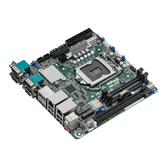
Page 9: Motherboard Layout
1.3 Motherboard Layout... - Page 10 1 : COM Port PWR Setting Jumper PWR_COM3 (For COM Port3) 2 : USB2.0 Header (USB2_8_9) 3 : USB3.2 Gen1 Header (USB3_3_4) 4 : SATA3 Connectors (SATA3_1~4) 5 : 4-pin ATX Power Input/Output Connector 6 : 24-pin ATX Power Input Connector 7 : LVDS Panel Connector 8 : LVDSBL2 9 : Panel Power Select (LCD_VCC) (PNL_PWR1)
-
Page 11: I/O Panel
1.4 I/O Panel COM Port (COM1) (RS232/422/485)* Microphone (Pink) COM Port (COM3) (RS232) USB2.0 Ports (USB2_5_6) DisplayPort (D1) USB3.2 Gen1 Ports (USB3_1_2) LAN RJ-45 Port (LAN1)** HDMI Port (HDMI1) LAN RJ-45 Port (LAN2)** D-Sub Port (VGA1) Line out (Lime) COM Port (COM2) (RS232/422/485)* * This motherboard supports RS232/422/485 on COM1, 2 ports. -
Page 12: Chapter 2: Installation
Chapter 2: Installation This is a Mini-ITX form factor (6.7” x 6.7”, 17.0 x 17.0 cm) motherboard. Before you install the motherboard, study the configuration of your chassis to ensure that the motherboard fits into it. Make sure to unplug the power cord before installing or removing the motherboard. -
Page 13: Installation Of Memory Modules (So-Dimm)
2.3 Installation of Memory Modules (SO-DIMM) This motherboard provides two 260-pin DDR4 (Double Data Rate 4) SO-DIMM slots. 1. The SO-DIMM only fits in one correct orientation. It will cause permanent damage to the motherboard and the SO-DIMM if you force the SO-DIMM into the slot at incorrect orientation. -
Page 15: Expansion Slots
2.4 Expansion Slots There are 2 M.2 sockets and 1 PCI Express slot on this motherboard. M.2 sockets: 1 x M.2 (Key E, 2230) with PCIe x1, USB 2.0 for Wireless. 1 x M.2 (Key M, 2242/2260/2280) with PCIE x4 . PCIE slot: PCIE1 (PCIE 3.0 x16 slot) is used for PCI Express x16 lane width cards. -
Page 16: Jumpers Setup
2.5 Jumpers Setup The illustration shows how jumpers are setup. When the jumper cap is placed on pins, the jumper is “Short”. If no jumper cap is placed on pins, the jumper is “Open”. The illus- tration shows a 3-pin jumper whose pin1 and pin2 are “Short”... - Page 17 COM Port PWR Setting Jumpers 1-2 : +5V 2-3 : +12V (3-pin PWR_COM1 (For COM Port1)) (see p. 9, No. 3) (3-pin PWR_COM4 (For COM Port4)) (see p. 9, No. 23) Chassis Intrusion Headers This motherboard supports CASE OPEN detection feature (2-pin CI1, CI2: see p.
- Page 18 ATX/AT Mode Jumper Open : ATX Mode Short : AT Mode (2-pin SIO_AT1) (see p. 9, No. 29) Digital Input / Output Power Select 1-2 : +12V 2-3 : +5V (3-pin JGPIO_PWR1) (see p. 9, No. 24)
-
Page 19: Onboard Headers And Connectors
2.6 Onboard Headers and Connectors Onboard headers and connectors are NOT jumpers. Do NOT place jumper caps over these headers and connectors. Placing jumper caps over the headers and connectors will cause permanent damage of the motherboard! CPU Fan Connector (+12V) Please connect the CPU fan cable to the connector and (4-pin CPU_FAN1) - Page 20 Connect the power switch, reset switch and system status indicator on the chassis to this header according to the pin assignments below. Note the positive and negative pins before connecting the cables. PWRBTN (Power Switch): Connect to the power switch on the chassis front panel. You may configure the way to turn off your system using the power switch.
- Page 21 Front Panel Audio Header This is an interface for front OUT_RET OUT2_L panel audio cable that allows (9-pin HD_AUDIO1) J_SENSE MIC_RET OUT2_R convenient connection and (see p. 9 No. 31) MIC2_R control of audio devices. MIC2_L 1. High Definition Audio supports Jack Sensing, but the panel wire on the chassis must support HDA to function correctly.
- Page 22 ATX Power Input/Output Connector Please connect a DC power supply to this (4-pin ATX12V1) connector. (see p. 9 No. 5) 1-2 : GND 3-4 : DC Input ATX Power Input Connector This motherboard provides a 24-pin ATX power connector. (24-pin ATXPWR1) To use a 20-pin ATX power (see p.
- Page 23 Inverter Power Control Wafer Signal Name (6-pin BLT_PWR1) (see p. 9 No. 10) CON_LBKLT_CTL CON_LBKLT_EN LCD_BLT_VCC LCD_BLT_VCC Backlight Volume Control Signal Name GPIO_VOL_UP (7-pin BLT_VOL1) GPIO_VOL_DW (see p. 9 No. 13) PWRDN BLT_UP BLT_DW...
-
Page 24: Chapter 3: Uefi Setup Utility
Chapter 3: UEFI SETUP UTILITY 3.1 Introduction This section explains how to use the UEFI SETUP UTILITY to configure your system. The UEFI chip on the motherboard stores the UEFI SETUP UTILITY. You may run the UEFI SETUP UTILITY when you start up the computer. Please press <F2>... -
Page 25: Navigation Keys
3.1.2 Navigation Keys Please check the following table for the function description of each navigation key. Navigation Key(s) Function Description Moves cursor left or right to select Screens Moves cursor up or down to select items + / - To change option for the selected items <Enter>... -
Page 26: Advanced Screen
3.3 Advanced Screen In this section, you may set the configurations for the following items: CPU Configu- ration, Chipset Configuration, Storage Configuration, Super IO Configuration, ACPI Configuration, USB Configuration and Trusted Computing. Setting wrong values in this section may cause the system to malfunction. -
Page 27: Cpu Configuration
3.3.1 CPU Configuration Intel Hyper Threading Technology Intel Hyper Threading Technology allows multiple threads to run on each core, so that the overall performance on threaded software is improved. Active Processor Cores Select the number of cores to enable in each processor package. CPU C States Support Enable CPU C States Support for power saving. - Page 28 Turbo Mode Use this item to enable or disable Intel Turbo Boost Mode Technology. Turbo Boost Mode allows processor cores to run faster than marked fre- quency in specific conditions. The default value is [Enabled]. CPU Thermal Throttling You may select [Enabled] to enable CPU internal thermal control mechanism to keep the CPU from overheating.
-
Page 29: Chipset Configuration
3.3.2 Chipset Configuration Primary Graphics Adapter This allows you to select [Onboard] or [PCI Express] as the boot graphic adapter priority. The default value is [PCI Express]. Above 4G Decoding Enable or disable 64bit capable Devices to be decoded in Above 4G Ad- dress Space (only if the system supports 64 bit PCI decoding). - Page 30 Panel Type Selection Use this to select panel type. This item appears when you enable Active LVDS. The default values of Active LVDS and Panel Type Selec- tion will be changed only when the users manually adjust them. They will keep at the default values no matter you clear CMOS, use Instant Flash or press <F9>.
-
Page 31: Storage Configuration
3.3.3 Storage Configuration SATA Controller(s) Use this item to enable or disable the SATA Controller feature. SATA Mode Selection Use this to select SATA mode. The default value is [AHCI Mode]. AHCI (Advanced Host Controller Interface) supports NCQ and other new features that will improve SATA disk perfor- mance. -
Page 32: Super Io Configuration
3.3.4 Super IO Configuration COM1 Configuration Use this to set parameters of COM1. Type Select Use this to select COM3 port type: [RS232], [RS422] or [RS485]. COM2 Configuration Use this to set parameters of COM2. Type Select Use this to select COM2 port type: [RS232], [RS422] or [RS485]. COM3 Configuration Use this to set parameters of COM3. -
Page 33: Acpi Configuration
3.3.5 ACPI Configuration Suspend to RAM Use this item to select whether to auto-detect or disable the Suspend-to- RAM feature. Select [Auto] will enable this feature if the OS supports it. PCIE Devices Power On Use this item to enable or disable PCIE devices to turn on the system from the power-soft-off mode. -
Page 34: Usb Configuration
3.3.6 USB Configuration Legacy USB Support Use this option to select legacy support for USB devices. There are two configuration options: [Enabled] and [UEFI Setup Only]. The default value is [Enabled]. Please refer to below descriptions for the details of these two options: [Enabled] - Enables support for legacy USB. -
Page 35: Trusted Computing
3.3.7 Trusted Computing Security Device Support Enable or disable BIOS support for security device. Onboard TPM Use this to enable or disable onboard TPM. The default is [Enabled]. -
Page 36: Hardware Health Event Monitoring Screen
3.4 Hardware Health Event Monitoring Screen In this section, it allows you to monitor the status of the hardware on your system, including the parameters of the CPU temperature, motherboard temperature, CPU fan speed, chassis fan speed, and the critical voltage. CPU_FAN1 Setting This allows you to set CPU fan 1’s speed. -
Page 37: Security Screen
3.5 Security Screen In this section, you may set, change or clear the supervisor/user password for the system. Supervisor Password Set or change the password for the administrator account. Only the ad- ministrator has authority to change the settings in the UEFI Setup Utility. Leave it blank and press enter to remove the password. -
Page 38: Boot Screen
3.6 Boot Screen In this section, it will display the available devices on your system for you to config- ure the boot settings and the boot priority. Boot From Onboard LAN Use this item to enable or disable the Boot From Onboard LAN feature. Setup Prompt Timeout This shows the number of seconds to wait for setup activation key. - Page 39 CSM (Compatibility Support Module) Use this to enable or disable Compatibility Support Module. The default value is [Disabled]. Launch PXE OpROM Policy Select UEFI only to run those that support UEFI option ROM only. Select Legacy only to run those that support legacy option ROM only. Select Do not launch to not execute both legacy and UEFI option ROM.
-
Page 40: Exit Screen
3.7 Exit Screen Save Changes and Exit When you select this option, it will pop-out the following message, “Save configuration changes and exit setup?” Select [OK] to save the changes and exit the UEFI SETUP UTILITY. Discard Changes and Exit When you select this option, it will pop-out the following message, “Discard changes and exit setup?”... -
Page 41: Chapter 4: Software Support
Chapter 4: Software Support 4.1 Install Operating System ® ® This motherboard supports various Microsoft Windows operating systems: 10 64- bit. Because motherboard settings and hardware options vary, use the setup proce- dures in this chapter for general reference only. Refer your OS documentation for more information.
Need help?
Do you have a question about the IMB-1225 and is the answer not in the manual?
Questions and answers