
Related Manuals for ASRock Industrial IMB-159


Summary of Contents for ASRock Industrial IMB-159
- Page 1 IMB-159 User Manual Version 1.0 Published April 2018 Copyright©2018 ASRockind INC. All rights reserved.
- Page 2 Version 1.0 Published April 2018 Copyright©2018 ASRockind INC. All rights reserved. Copyright Notice: No part of this documentation may be reproduced, transcribed, transmitted, or translated in any language, in any form or by any means, except duplication of documentation by the purchaser for backup purpose, without written consent of ASRockind Inc.
- Page 3 CAUTION: RISK OF EXPLOSION IF BATTERY IS REPLACED BY AN INCORRECT TYPE. DISPOSE OF USED BATTERIES ACCORDING TO THE INSTRUCTIONS.
-
Page 4: Table Of Contents
Contents 1 Introduction ............5 1.1 Package Contents ............5 1.2 Specifications ..............6 1.3 Motherboard Layout ............8 1.4 I/O Panel ................ 10 2 Installation ............11 2.1 Screw Holes ..............11 2.2 Pre-installation Precautions ........... 11 2.3 Installation of Memory Modules (SO-DIMM) ....12 2.4 Expansion Slot ............... -
Page 5: Introduction
Chapter 1: Introduction Thank you for purchasing ASRockind IMB-159 motherboard, a reliable motherboard produced under ASRockind’s consistently stringent quality control. It delivers ex- cellent performance with robust design conforming to ASRockind’s commitment to quality and endurance. In this manual, chapter 1 and 2 contain introduction of the motherboard and step- by-step guide to the hardware installation. -
Page 6: Specifications
1.2 Specifications Form Dimensions Mini-ITX (6.7-in x 6.7-in) Factor BGA1090 for Intel Gemini Lake SoC Processor Chipset System BIOS UEFI PCIe 1 x PCIe x1 slot Mini-PCIe 1 x Full/Half mini-PCIe with PCIe x1 and USB 2.0 mSATA Expansion 1 x M.2 (Key E, 2230) with PCIe x1, CNVI and Slot USB2.0 for Wireless 1 x M.2 (Key M, 2242/2260/2280) with SATA3... - Page 7 5 x USB2.0 (2 x headers, 1 x Type A) LVDS 1 (shared with eDP, auto detect) 1 (shared with VGA Con.) 2 x COM (RS-232/422/485), 4 x Serial COM(RS-232) Internal SATA 1 x SATA3 (6.0Gb/s) Connector Parallel 1 (shared with GPIO) GPIO 8 x GPI, 8 x GPO SATA PWR...
-
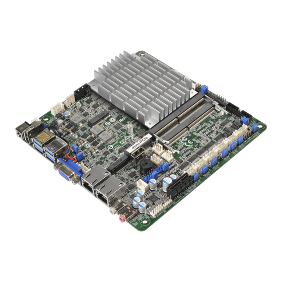
Page 8: Motherboard Layout
1.3 Motherboard Layout IMB-159 SATA3_1 DC_JACK1 Industrial TO_UPS1 SATA_PWR1 FROM_UPS1 DISPLAY1 USB 3.0 8 (*Backside: EDP1) T: USB1 B: USB0 M.2 KEY E USB 3.0 T: USB3 B: USB2 CLRMOS2 CLRMOS1 DDR4_A1 mini-PCIe M.2 KEY M LAN1 TPM1 DDR4_B1 Vertical Type A USB 2.0... - Page 9 1 : 2-pin UPS Module Power Input Connector 2 : USB Power Setting Jumpers (USB3_PWR0_1 (For USB3_0_1)) (USB3_PWR2_3 (For USB3_2_3)) 3 : 4-pin DC-in PWR Connector (Input +12V or +19V~+28V) & UPS Module Power Output Connector 4 : SATA Power Output Connector 5 : SATA3 Connector (SATA3_1) 6 : M.2 KEY E 7 : BL1, BL2...
-
Page 10: I/O Panel
1.4 I/O Panel DC Jack LAN RJ-45 Port (LAN1)* DisplayPort (DP1) LAN RJ-45 Port (LAN2)* USB 3.0 Ports (USB3_0_1) Line out (Green) USB 3.0 Ports (USB3_2_3) Microphone (Pink) VGA Port (VGA1) * There are two LED next to the LAN port. Please refer to the table below for the LAN port LED indications. -
Page 11: Installation
Chapter 2: Installation This is a Mini-ITX form factor (6.7" x 6.7", 17.0 x 17.0 cm) motherboard. Before you install the motherboard, study the configuration of your chassis to ensure that the motherboard fits into it. Make sure to unplug the power cord before installing or removing the motherboard. -
Page 12: Installation Of Memory Modules (So-Dimm)
2.3 Installation of Memory Modules (SO-DIMM) IMB-159 motherboard provides two 260-pin DDR4 (Double Data Rate 4) SO-DIMM slots, and supports Dual Channel Memory Technology. 1. If you install one memory module only, please install it on DDR4_A1. 2. It is not allowed to install a DDR, DDR2 or DDR3 memory module into a DDR4 slot;... -
Page 13: Expansion Slot
2.4 Expansion Slots (mini-PCIe, PCI Express and M.2 Slots) There is 1 mini-PCIe slot, 1 PCI Express slot and 2 M.2 slots on this motherboard. mini-PCIe slot: MINI_PCIE1 (mini-PCIe slot; half/full size) is used for PCI Express mini cards. PCIE slot: PCIE1 (PCIE x1 slot) is used for PCI Express x1 lane width cards. M.2 slots: M2 Slot (Key M) supports type 2242/2260/2280 M.2 SATA3 6.0 Gb/s module. -
Page 14: Jumpers Setup
2.5 Jumpers Setup The illustration shows how jumpers are setup. When the jumper cap is placed on pins, the jumper is “Short”. If no jumper cap is placed on pins, the jumper is “Open”. The illustration shows a 3-pin jumper whose pin1 and pin2 are “Short”... - Page 15 ATX/AT Mode Select 1-2: AT Mode 2-3: ATX Mode (3-pin PWR_JP1) (see p.8 No. 11) Panel Power Select (LCD_VCC) Use this to set up the VDD power of the LVDS connector. (5-pin PNL_PWR1) 1-2: LCD_VCC: +3V (see p.8 No. 13) 2-3: LCD_VCC: +5V 4-5: LCD_VCC: +12V Backlight Power Select...
- Page 16 Digital Input / Output Default Value Setting 1-2: Pull-High 2-3: Pull-Low (3-pin JGPIO_SET1) (see p.8, No. 20)
-
Page 17: Onboard Headers And Connectors
2.6 Onboard Headers and Connectors Onboard headers and connectors are NOT jumpers. Do NOT place jumper caps over these headers and connectors. Placing jumper caps over the headers and connectors will cause permanent damage of the motherboard! SATA3 Connector This Serial ATA3 (SATA3) connector supports (SATA3_1: see p.8, No. - Page 18 HDLED (Hard Drive Activity LED): Connect to the hard drive activity LED on the chassis front panel. The LED is on when the hard drive is reading or writing data. The front panel design may differ by chassis. A front panel module mainly consists of power switch, reset switch, power LED, hard drive activity LED, speaker and etc.
- Page 19 Chassis Fan Connector Please connect the fan cable to the fan connector and FAN_SPEED_CONTROL (4-pin CHA_FAN1) FAN_SPEED match the black wire to the (see p.8 No. 24) +12V ground pin. CPU Fan Connector Please connect the CPU fan cable to the connector and (4-pin CPU_FAN1) FAN_SPEED_CONTROL FAN_SPEED...
- Page 20 LVDS Connector Signal Name Signal Name LCD_VCC LCD_VCC (40-pin LVDS1) LDDC_CLK +3.3V LVDS_A_DATA0# LDDC_DATA (see p.8 No. 8) LVDS_A_DATA0 LVDS_A_DATA1 LVDS_A_DATA1# LVDS_A_DATA2# LVDS_A_DATA2 LVDS_A_DATA3 LVDS_A_DATA3# LVDS_A_CLK# LVDS_A_CLK LVDS_B_DATA0 LVDS_B_DATA0# LVDS_B_DATA1# LVDS_B_DATA1 LVDS_B_DATA2 LVDS_B_DATA2# LVDS_B_DATA3# DPLVDD_EN LVDS_B_DATA3 LVDS_B_CLK LVDS_B_CLK# CON_LBKLT_EN LCD_BLT_VCC CON_LBKLT_CTL LCD_BLT_VCC LCD_BLT_VCC...
- Page 21 Backlight Volume Control Signal Name GPIO_VOL_UP (7-pin BLT_VOL1) GPIO_VOL_DW (see p.8 No. 10) PWRDN BRIGHTNESS_UP BRIGHTNESS_DW Backlight Power Connector Signal Name (6-pin BLT_PWR1) (see p.8 No. 12) CON_LBKLT_CTL CON_LBKLT_EN LCD_BLT_VCC LCD_BLT_VCC SATA Power Output Connector (4-pin SATA_PWR1) (see p.8 No. 4) +12V Buzzer Header (2-pin BUZZ2)
- Page 22 Internal COM Port Headers: COM1, 2 (RS232/422/485) COM3, 4, 5, 6 (RS232) (10-pin COM1~6: see p.8, No. 17) Signal Signal Signal Signal Signal Name Name Name Name Name CCTS# DDSR# DDTR# RRXD RRTS# TTXD DDCD# * This motherboard supports RS232/422/485 on COM1, 2 ports. Please refer to below table for the pin definition. In addition, COM1, 2 ports (RS232/422/485) can be adjusted in BIOS setup utility >...
- Page 23 M.2 Socket (KEY M) see p.8, No. 34) SATA_RX SATA_RX# SATA_TX# SATA_TX M.2 Socket (KEY E) see p.8, No. 6)
- Page 24 Vertical Type A USB 2.0 Port There is one Vertical Type A USB 2.0 port on this (see p.8 No. 32) motherboard. SPI TPM Header (9-pin SPI_TPM1) (see p.8 No. 15)
-
Page 25: Uefi Setup Utility
Chapter 3: UEFI SETUP UTILITY 3.1 Introduction This section explains how to use the UEFI SETUP UTILITY to configure your system. The UEFI chip on the motherboard stores the UEFI SETUP UTILITY. You may run the UEFI SETUP UTILITY when you start up the computer. Please press <F2>... -
Page 26: Navigation Keys
3.1.2 Navigation Keys Please check the following table for the function description of each navigation key. Navigation Key(s) Function Description Moves cursor left or right to select Screens Moves cursor up or down to select items + / - To change option for the selected items <Enter>... -
Page 27: Advanced Screen
3.3 Advanced Screen In this section, you may set the configurations for the following items: CPU Configu- ration, Chipset Configuration, Storage Configuration, Super IO Configuration, ACPI Configuration and USB Configuration. Setting wrong values in this section may cause the system to malfunction. Instant Flash Instant Flash is a UEFI flash utility embedded in Flash ROM. -
Page 28: Cpu Configuration
3.3.1 CPU Configuration Intel SpeedStep Technology Intel SpeedStep technology is Intel’s new power saving technology. Pro- cessors can switch between multiple frequencies and voltage points to en- able power saving. The default value is [Enabled]. Configuration options: ® [Enabled] and [Disabled]. If you install Windows OS and want to enable this function, please set this item to [Enabled]. -
Page 29: Chipset Configuration
3.3.2 Chipset Configuration Primary Graphics Adapter This allows you to select [Onboard] or [PCI Express] as the boot graphic adapter priority. The default value is [Onboard]. Share Memory Configure the size of memory that is allocated to the integrated graphics processor when the system boots up. - Page 30 Onboard LAN 1 This allows you to enable or disable the Onboard LAN 1 feature. Onboard LAN 2 This allows you to enable or disable the Onboard LAN 2 feature. PCIE1 Link Speed Select the link speed for PCIE1. PCIE1 ASPM Enable or disable PCIE1 ASPM.
-
Page 31: Storage Configuration
3.3.3 Storage Configuration SATA Controller(s) Use this item to enable or disable the SATA Controller feature. SATA Mode Selection Use this to select SATA mode. The default value is [AHCI Mode]. Aggressive Link Power Management Use this item to configure Aggressive Link Power Management. Hard Disk S.M.A.R.T. -
Page 32: Super Io Configuration
3.3.4 Super IO Configuration COM1 Use this to enable or disable COM1. Type Select Use this to select COM1 port type: [RS232], [RS422] or [RS485]. COM2 Use this to enable or disable COM2. Type Select Use this to select COM2 port type: [RS232], [RS422] or [RS485]. COM3 Use this to enable or disable COM3. - Page 33 WDT Timeout Reset This allows users to enable/disable the Watch Dog Timer timeout to reset system. The default value is [Disabled].
-
Page 34: Acpi Configuration
3.3.5 ACPI Configuration Suspend to RAM Use this item to select whether to auto-detect or disable the Suspend-to- RAM feature. Select [Auto] will enable this feature if the OS supports it. ACPI HPET Table Use this item to enable or disable ACPI HPET Table. The default value is [Enabled]. -
Page 35: Trusted Computing
3.3.6 Trusted Computing Security Device Support Enable or disable BIOS support for security device. -
Page 36: Hardware Health Event Monitoring Screen
3.4 Hardware Health Event Monitoring Screen In this section, it allows you to monitor the status of the hardware on your system, including the parameters of the CPU temperature, motherboard temperature, CPU fan speed, chassis fan speed, and the critical voltage. CPU_FAN1 Setting This allows you to set CPU_FAN1’s speed. -
Page 37: Security Screen
3.5 Security Screen In this section, you may set, change or clear the supervisor/user password for the system. Supervisor Password Set or change the password for the administrator account. Only the ad- ministrator has authority to change the settings in the UEFI Setup Utility. Leave it blank and press enter to remove the password. -
Page 38: Boot Screen
3.6 Boot Screen In this section, it will display the available devices on your system for you to config- ure the boot settings and the boot priority. Boot From Onboard LAN Use this item to enable or disable the Boot From Onboard LAN feature. Setup Prompt Timeout This shows the number of seconds to wait for setup activation key. - Page 39 CSM (Compatibility Support Module) Enable to launch the Compatibility Support Module. Please do not disable unless you’re running a WHCK test. If you are using Windows 8 / 8.1 64- bit and all of your devices support UEFI, you may also disable CSM for faster boot speed.
-
Page 40: Exit Screen
3.7 Exit Screen Save Changes and Exit When you select this option, it will pop-out the following message, “Save configuration changes and exit setup?” Select [OK] to save the changes and exit the UEFI SETUP UTILITY. Discard Changes and Exit When you select this option, it will pop-out the following message, “Discard changes and exit setup?”... -
Page 41: Software Support
Chapter 4: Software Support 4.1 Install Operating System ® ® This motherboard supports Microsoft Windows operating systems: 10 32-bit / 10 64-bit / 8.1 64-bit / 8 64-bit / 7 32-bit / 7 64-bit. Because motherboard settings and hardware options vary, use the setup procedures in this chapter for general refer- ence only.
Need help?
Do you have a question about the IMB-159 and is the answer not in the manual?
Questions and answers