
Subscribe to Our Youtube Channel
Related Manuals for ASRock Industrial IMB-157


Summary of Contents for ASRock Industrial IMB-157
- Page 1 IMB-157 User Manual Version 1.1 Updated March 2023 Copyright©2023 ASRockInd INC. All rights reserved.
- Page 2 Version 1.0 Published May 2017 Copyright©2023 ASRockInd INC. All rights reserved. Copyright Notice: No part of this documentation may be reproduced, transcribed, transmitted, or translated in any language, in any form or by any means, except duplication of documentation by the purchaser for backup purpose, without written consent of ASRockInd Inc.
- Page 3 ® The terms HDMI and HDMI High-Definition Multimedia Interface, and the HDMI logo are trademarks or registered trademarks of HDMI Licensing LLC in the United States and other countries. CAUTION: RISK OF EXPLOSION IF BATTERY IS REPLACED BY AN INCORRECT TYPE. DISPOSE OF USED BATTERIES ACCORDING TO THE INSTRUCTIONS.
-
Page 4: Table Of Contents
Contents 1 Introduction 1.1 Package Contents 1.2 Specifications 1.3 Motherboard Layout 1.4 I/O Panel 2 Installation 2.1 Screw Holes 2.2 Pre-installation Precautions 2.3 Installation of Memory Modules (SO-DIMM) 2.4 Expansion Slots 2.5 Jumpers Setup 2.6 Onboard Headers and Connectors 3 UEFI SETUP UTILITY 3.1 Introduction 3.1.1 UEFI Menu Bar 3.1.2 Navigation Keys... -
Page 5: Introduction
Chapter 1: Introduction Thank you for purchasing ASRockInd IMB-157 motherboard, a reliable motherboard produced under ASRockInd’s consistently stringent quality control. It delivers ex- cellent performance with robust design conforming to ASRockInd’s commitment to quality and endurance. In this manual, chapter 1 and 2 contain introduction of the motherboard and step- by-step guide to the hardware installation. -
Page 6: Specifications
1.2 Specifications Form Mini-ITX (6.7-in x 6.7-in x 0.84-in, 17.0 cm x Dimensions Factor 17.0 cm x 2.13 cm) ® Intel Apollo Lake SoC Processors IMB-157D (N4200, QC, 1.10 GHz, 6 W) Processor IMB-157L (N3350, DC, 1.10 GHz, 6 W) System IMB-157J (J3455, QC, 1.50 GHz, 10 W) BIOS... - Page 7 4 x USB 2.0 (2x2.54mm header) LVDS 1 (shared with eDP, switch by BIOS) 1 (shared with LVDS, switch by BIOS) 1 x Header (Shared with VGA Port) COM1, COM2 (RS-232/422/485) Internal COM3, COM4, COM5, COM6 (RS-232) Connector Parallel 1 (shared with GPIO) GPIO 8 x GPI, 8 x GPO (shared with LPT header) SATA PWR...
-
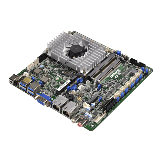
Page 8: Motherboard Layout
USB6_S_MPCIE1 USB4_S_M2E1 DDR3_B1 (Support DDR3L Only) PS2_KB_MS1 CLRMOS1 LAN1 CHA_FAN1 CPU_FAN1 BUZZ1 DDR3_A1 (Support DDR3L Only) CLRMOS2 PWR_JP1 LAN2 PANEL1 Industrial IMB-157 M.2 KEY E Line Out BIOS Mic In Chip AUDIO CODEC LPC1 COM1 COM2 COM3 COM4 COM5 COM6... - Page 9 1 : 2-pin UPS Module Power Input Connector 2 : USB Power Setting Jumpers (USB3_PWR0_1 (For USB3_0_1)) (USB3_PWR2_3 (For USB3_2_3)) 3 : 4-pin DC-in PWR Connector (Input +12V or +19V~+24V) & UPS Module Power Output Connector 4 : SATA Power Output Connector 5 : SATA3 Connector (SATA3_1) 6 : BL1, BL2 7 : LVDS Panel Connector...
-
Page 10: I/O Panel
1.4 I/O Panel DC Jack LAN RJ-45 Port (LAN1)* HDMI Port (HDMI1) LAN RJ-45 Port (LAN2)* USB3.2 Gen1 Ports (USB3_0_1) Line out (Green) USB3.2 Gen1 Ports (USB3_2_3) Microphone (Pink) VGA Port (VGA1) * There are two LED next to the LAN port. Please refer to the table below for the LAN port LED indications. -
Page 11: Installation
Chapter 2: Installation This is a Mini-ITX form factor (6.7" x 6.7", 17.0 x 17.0 cm) motherboard. Before you install the motherboard, study the configuration of your chassis to ensure that the motherboard fits into it. Make sure to unplug the power cord before installing or removing the motherboard. -
Page 12: Installation Of Memory Modules (So-Dimm)
2.3 Installation of Memory Modules (SO-DIMM) IMB-157 motherboard provides two 204-pin DDR3 (Double Data Rate 3) SO-DIMM slots, which support Dual Channel DDR3L (low voltage). 1. If you install one memory module only, please install it on DDR3_A1. 2. It is not allowed to install a DDR or DDR2 memory module into a DDR3 slot;... -
Page 13: Expansion Slots
2.4 Expansion Slots (mini-PCIe, PCI Express and M.2 Slots) There is 1 mini-PCIe slot, 1 PCI Express slot and 2 M.2 slots on this motherboard. mini-PCIe slot: MINI_PCIE1 (mini-PCIe slot; half/full size) is used for PCI Express mini cards. PCIE slot: PCIE1 (PCIE x1 slot) is used for PCI Express x1 lane width cards. M.2 slots: M2 Slot (Key M) supports type 2242/2260 M.2 SATA3 6.0 Gb/s module. -
Page 14: Jumpers Setup
2.5 Jumpers Setup The illustration shows how jumpers are setup. When the jumper cap is placed on pins, the jumper is “Short”. If no jumper cap is placed on pins, the jumper is “Open”. The illustration shows a 3-pin jumper whose pin1 and pin2 are “Short”... - Page 15 ATX/AT Mode Select 1-2: AT Mode 2-3: ATX Mode (3-pin PWR_JP1) (see p.8 No. 26) Panel Power Select (LCD_VCC) Use this to set up the VDD power of the LVDS connector. (5-pin PNL_PWR1) 1-2: LCD_VCC: +3V (see p.8 No. 13) 2-3: LCD_VCC: +5V 4-5: LCD_VCC: +12V Backlight Power Select...
- Page 16 USB Power Setting Jumpers 1-2: +5V (3-pin USB2_PWR4_5 (For USB2_4_5)) 2-3: +5VSB (3-pin USB2_PWR6_7 (For USB2_6_7 and PS2_KB_MS1)) (see p.8, No. 37) Digital Input / Output Default Value Setting 1-2: Pull-High 2-3: Pull-Low (3-pin JGPIO_SET1) (see p.8, No. 19) USB6_S_MPCIE1 USB6_S_MPCIE1: Pin1 short USB2_6_7 pin3 and pin2 (2-pin USB6_S_MPCIE1)
-
Page 17: Onboard Headers And Connectors
2.6 Onboard Headers and Connectors Onboard headers and connectors are NOT jumpers. Do NOT place jumper caps over these headers and connectors. Placing jumper caps over the headers and connectors will cause permanent damage of the motherboard! SATA3 Connector This Serial ATA3 (SATA3) connector supports (SATA3_1: see p.8, No. - Page 18 PLED (System Power LED): Connect to the power status indicator on the chassis front panel. The LED is on when the system is operating. The LED keeps blinking when the sys- tem is in S1 sleep state. The LED is off when the system is in S3/S4 sleep state or powered off (S5).
- Page 19 4-Pin Chassis Fan Connector (+12V) Please connect the fan cable FAN_SPEED_CONTROL to the fan connector and (4-pin CHA_FAN1) FAN_SPEED +12V match the black wire to the (see p.8 No. 23) ground pin. 4-Pin CPU Fan Connector (+12V) Please connect the CPU fan FAN_SPEED_CONTROL FAN_SPEED cable to the fan connector and...
- Page 20 LVDS Connector Signal Name Signal Name LCD_VCC LCD_VCC (40-pin LVDS1) +3.3V LVDS_A_DATA0# (see p.8 No. 7) LVDS_A_DATA0 LVDS_A_DATA1 LVDS_A_DATA1# LVDS_A_DATA2# LVDS_A_DATA2 LVDS_A_DATA3 LVDS_A_DATA3# LVDS_A_CLK# LVDS_A_CLK LVDS_B_DATA0 LVDS_B_DATA0# LVDS_B_DATA1# LVDS_B_DATA1 LVDS_B_DATA2 LVDS_B_DATA2# LVDS_B_DATA3# DPLVDD_EN LVDS_B_DATA3 LVDS_B_CLK LVDS_B_CLK# CON_LBKLT_EN LCD_BLT_VCC CON_LBKLT_CTL LCD_BLT_VCC LCD_BLT_VCC * eDP Connector (on the Backside of PCB) Signal Name...
- Page 21 Backlight Volume Control Signal Name GPIO_VOL_UP (7-pin BLT_VOL1) GPIO_VOL_DW (see p.8 No. 10) PWRDN BRIGHTNESS_UP BRIGHTNESS_DW Backlight Power Connector Signal Name (6-pin BLT_PWR1) (see p.8 No. 11) CON_LBKLT_CTL CON_LBKLT_EN LCD_BLT_VCC LCD_BLT_VCC SATA Power Output Connector (4-pin SATA_PWR1) (see p.8 No. 4) +12V Buzzer Header (2-pin BUZZ2)
- Page 22 Internal COM Port Headers: COM1, 2 (RS232/422/485) COM3, 4, 5, 6 (RS232) (10-pin COM1~6: see p.8, No. 17) Signal Signal Signal Signal Signal Name Name Name Name Name CCTS# DDSR# DDTR# RRXD RRTS# TTXD DDCD# * This motherboard supports RS232/422/485 on COM1, 2 ports. Please refer to below table for the pin definition. In addition, COM1, 2 ports (RS232/422/485) can be adjusted in BIOS setup utility >...
- Page 23 M.2 KEY M (M2) Signal Signal +3.3V +3.3V +3.3V +3.3V +3.3V +3.3V SMB_CLK SATA_RX SMB_DATA SATA_RX# SATA_TX# SATA_TX +3.3V +3.3V +3.3V M.2 KEY E (M2_2) Signal Signal +3.3V USB_D+ +3.3V USB_D- PETp PETn PERp PERn PEFCLKp PEFCLKn CLKREQ# PERST0# WAKE# SMB_DATA SMB_CLK +3.3V...
-
Page 24: Uefi Setup Utility
Chapter 3: UEFI SETUP UTILITY 3.1 Introduction This section explains how to use the UEFI SETUP UTILITY to configure your system. The UEFI chip on the motherboard stores the UEFI SETUP UTILITY. You may run the UEFI SETUP UTILITY when you start up the computer. Please press <F2>... -
Page 25: Navigation Keys
3.1.2 Navigation Keys Please check the following table for the function description of each navigation key. Navigation Key(s) Function Description Moves cursor left or right to select Screens Moves cursor up or down to select items + / - To change option for the selected items <Enter>... -
Page 26: Advanced Screen
3.3 Advanced Screen In this section, you may set the configurations for the following items: CPU Configu- ration, Chipset Configuration, Storage Configuration, Super IO Configuration, ACPI Configuration, USB Configuration, and Trusted Computing. Setting wrong values in this section may cause the system to malfunction. -
Page 27: Cpu Configuration
3.3.1 CPU Configuration Intel SpeedStep Technology Intel SpeedStep technology is Intel’s new power saving technology. Pro- cessors can switch between multiple frequencies and voltage points to en- able power saving. The default value is [Enabled]. Configuration options: ® [Enabled] and [Disabled]. If you install Windows OS and want to enable this function, please set this item to [Enabled]. -
Page 28: Chipset Configuration
3.3.2 Chipset Configuration DRAM Frequency If [Auto] is selected, the motherboard will detect the memory module(s) inserted and assign the appropriate frequency automatically. Primary Graphics Adapter This allows you to select [Onboard] or [PCI Express] as the boot graphic adapter priority. The default value is [Onboard]. Share Memory Configure the size of memory that is allocated to the integrated graphics processor when the system boots up. -
Page 29: Storage Configuration
3.3.3 Storage Configuration SATA Controller(s) Use this item to enable or disable the SATA Controller feature. SATA Mode Selection Use this to select SATA mode. The default value is [AHCI Mode]. Aggressive Link Power Management Use this item to configure Aggressive Link Power Management. Hard Disk S.M.A.R.T. -
Page 30: Super Io Configuration
3.3.4 Super IO Configuration COM1 Use this to enable or disable COM1. Type Select Use this to select COM1 port type: [RS232], [RS422] or [RS485]. COM2 Use this to enable or disable COM2. Type Select Use this to select COM2 port type: [RS232], [RS422] or [RS485]. COM3 Use this to enable or disable COM3. -
Page 31: Acpi Configuration
3.3.5 ACPI Configuration Suspend to RAM Use this item to select whether to auto-detect or disable the Suspend-to- RAM feature. Select [Auto] will enable this feature if the OS supports it. ACPI HPET Table Use this item to enable or disable ACPI HPET Table. The default value is [Enabled]. -
Page 32: Usb Configuration
3.3.6 USB Configuration Legacy USB Support Use this option to select legacy support for USB devices. There are four configuration options: [Enabled], [Auto] and [UEFI Setup Only]. The default value is [Auto]. Please refer to below descriptions for the details of these four options: [Enabled] - Enables support for legacy USB. -
Page 33: Trusting Computing
3.3.7 Trusting Computing NOTE: Options vary depending on the version of your connected TPM module. Security Device Support Security Device Support allows you to enable or disable BIOS support for security device. O.S. will not show Security Device. TCG EFI protocol and INT1A interface will not be available. - Page 34 Storage Hierarchy This item allows you to enable or disable Storage Hierarchy. Configuration options: [Enabled] [Disabled] Endorsement Hierarchy This item allows you to enable or disable Endorsement Hierarchy. Configuration options: [Enabled] [Disabled] TPM2.0 UEFI Spec Version Select the TCG2 Spec Version Support, TCG_1_2: the Compatible mode for Win8/Win10, TCG_2: Support new TCG2 protocol and event format for Win10 or later Physical Presence Spec Version...
-
Page 35: Hardware Health Event Monitoring Screen
3.4 Hardware Health Event Monitoring Screen In this section, it allows you to monitor the status of the hardware on your system, including the parameters of the CPU temperature, motherboard temperature, CPU fan speed, chassis fan speed, and the critical voltage. CPU_FAN1 Setting This allows you to set CPU_FAN1’s speed. -
Page 36: Security Screen
3.5 Security Screen In this section, you may set, change or clear the supervisor/user password for the system. Supervisor Password Set or change the password for the administrator account. Only the ad- ministrator has authority to change the settings in the UEFI Setup Utility. Leave it blank and press enter to remove the password. -
Page 37: Boot Screen
3.6 Boot Screen In this section, it will display the available devices on your system for you to config- ure the boot settings and the boot priority. Boot From Onboard LAN Use this item to enable or disable the Boot From Onboard LAN feature. Setup Prompt Timeout This shows the number of seconds to wait for setup activation key. - Page 38 CSM (Compatibility Support Module) Enable to launch the Compatibility Support Module. Please do not disable unless you’re running a WHCK test. If you are using Windows 10 64-bit and all of your devices support UEFI, you may also disable CSM for faster boot speed.
-
Page 39: Exit Screen
3.7 Exit Screen Save Changes and Exit When you select this option, it will pop-out the following message, “Save configuration changes and exit setup?” Select [OK] to save the changes and exit the UEFI SETUP UTILITY. Discard Changes and Exit When you select this option, it will pop-out the following message, “Discard changes and exit setup?”... -
Page 40: Software Support
Chapter 4: Software Support 4.1 Install Operating System ® ® This motherboard supports Microsoft Windows operating systems: 10 64-bit. Be- cause motherboard settings and hardware options vary, use the setup procedures in this chapter for general reference only. Refer to your OS documentation for more information.
Need help?
Do you have a question about the IMB-157 and is the answer not in the manual?
Questions and answers