
Subscribe to Our Youtube Channel
Related Manuals for ASRock Industrial IMB-1315


Summary of Contents for ASRock Industrial IMB-1315
- Page 1 IMB-1315 User Manual Version 1.2 Updated November 7, 2023 Copyright©2023 ASRockInd INC. All rights reserved.
- Page 2 Version 1.0 Published August, 2023 Copyright©2023 ASRockInd INC. All rights reserved. Copyright Notice: No part of this documentation may be reproduced, transcribed, transmitted, or translated in any language, in any form or by any means, except duplication of documentation by the purchaser for backup purpose, without written consent of ASRockInd Inc.
- Page 3 WARNING THIS PRODUCT CONTAINS A BUTTOON BATTERY If swallowed, a button battery can cause serious injury or death. Please keep batteries out of sight or reach of children. CALIFORNIA, USA ONLY The Lithium battery adopted on this motherboard contains Perchlorate, a toxic substance controlled in Perchlorate Best Management Practices (BMP) regulations passed by the California Legislature.
-
Page 4: Table Of Contents
Contents Chapter 1 Introduction Package Contents Specifications Motherboard Layout I/O Panel Block Diagram Chapter 2 Installation Screw Holes Pre-installation Precautions Installation of Memory Modules (LONG-DIMM) Expansion Slots Jumpers Setup Onboard Headers and Connectors Chapter 3 UEFI SETUP UTILITY Introduction 3.1.1 Entering BIOS Setup 3.1.2 UEFI Menu Bar... - Page 5 3.3.4 Super IO Configuration 3.3.5 ACPI Configuration 3.3.6 USB Configuration 3.3.7 Trusted Computing 3.3.8 Thunderbolt (TM) Configuration Hardware Health Event Monitoring Screen 43 Security Screen 44 Boot Screen Exit Screen...
-
Page 6: Chapter 1 Introduction
If you require technical support related to this motherboard, please visit our website for specific information about the model you are using. https://www.asrockind.com/technical-support 1.1 Package Contents ASRockInd IMB-1315 Motherboard (Micro-ATX (9.6-in x 9.6-in x 1.56-in, 24.4 cm x 24.4 cm x 3.97 cm)) ASRockInd IMB-1315 Jumper Setting Instruction Gift Package:... -
Page 7: Specifications
1.2 Specifications Form Micro-ATX (9.6-in x 9.6-in x 1.56-in, 24.4 cm x 24.4 Dimensions Factor cm x 3.97 cm) Intel® 14th/13th/12th Gen (Raptor Lake-S Refresh/ Raptor Lake-S/Alder Lake-S) Core™ Processors, up to Processor System Chipset Intel® H610 Socket LGA 1700 BIOS AMI SPI 256 Mbit Dual Channel DDR5 4800/5600 MHz*... - Page 8 IMB-1315 1 x HDMI 2.0b HDMI 1 x HDMI 1.4b DisplayPort 1 x DP++ Ethernet 2 x 1 Gigabit LAN Rear I/O 4 x USB 3.2 Gen1 2 x USB 2.0 Audio 3 (Line-In/Line-Out/Mic-In) COM1 (RS-232/422/485) Serial Port COM2 (RS-232) 4 x USB 2.0 (1 x 2.54 pitch header, 2 x USB 2.0...
-
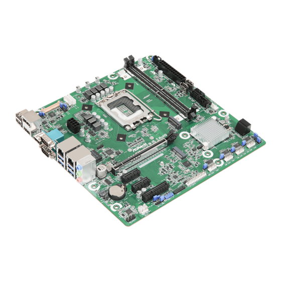
Page 9: Motherboard Layout
LAN_LED1 B: USB3_1 SATA3_4 USB 3.2 Gen1 Top: T: USB3_4 LAN1 B: USB3_3 PANEL1 Bottom: Center: Top: Industrial MIC IN LINE OUT LINE IN IMB-1315 CHA_FAN1 PCIE1 BUZZ1 PCIE2 BIOS CMOS Battery PCIE3 SATA3_6 SATA3_7 PWR_COM3 PWR_COM4 PWR_COM5 PWR_COM6 PCIE4... - Page 10 IMB-1315 1 : CON_LBKLT_CTL Voltage Level (BLT_PWM2) 2 : Brightness Control Mode (BLT_PWM1) 3 : LVDS Panel Connector (LVDS1) 4 : Panel Power Select (PNL_PWR1) 5 : Inverter Power Control Wafer (BLT_PWR1) 6 : Backlight Volume Control (BLT_VOL1) 7 : Backlight Power Select (LCD_BLT_VCC) (BKT_PWR1) 8 : 8-Pin ATX 12V Power Connector (ATX12V1) 9 : M.2 Key-M Socket (M2_M1)
- Page 11 38 : Buzzer Header (BUZZ2) 39 : Buzzer (BUZZ1) 40 : LAN LED Headers : LAN_LED1 (For LAN1 Port) LAN_LED2 (For LAN2 Port) 41 : COM Port Pin9 PWR Setting Jumpers PWR_COM1 (For COM Port1) PWR_COM2 (For COM Port2)
-
Page 12: I/O Panel
IMB-1315 1.4 I/O Panel USB 2.0 Ports (USB2_5_6) USB 3.2 Gen1 Ports (USB3_3_4) DisplayPort (DP1) USB 3.2 Gen1 Ports (USB3_1_2) COM Port (COM1) (RS232/422/485)* COM Port (COM2) (RS232) RJ45 LAN Port (LAN2)** 10 HDMI Port (HDMI2) (Supports HDMI 1.4b) RJ45 LAN Port (LAN1)** 11 HDMI Port (HDMI1) (Supports HDMI 2.0b) -
Page 13: Block Diagram
1.5 Block Diagram IMB-1315 Channel A DDR5 4800M/5600 HZ Chrontel LVDS/eDP U-DIMM LVDS/ DDIA CH7513A (A1) eDP Bypass mode (Option) Channel B DDR5 4800M/5600 HZ Intel U-DIMM (A2) HDMI 1.4b DDIB HDMI Alder Lake-S Connector Raptor Lake-S CPU PCIe Gen5 [0:15]... -
Page 14: Chapter 2 Installation
IMB-1315 Chapter 2 Installation This is a Micro-ATX (9.6-in x 9.6-in x 1.56-in, 24.4 cm x 24.4 cm x 3.97 cm) form factor motherboard. Before you install the motherboard, study the configuration of your chassis to ensure that the motherboard fits into it. -
Page 15: Installation Of Memory Modules (Long-Dimm)
2.3 Installation of Memory Modules (LONG-DIMM) IMB-1315 provides two 288-pin DDR5 (Double Data Rate 5) Long-DIMM slots, and supports Dual Channel Memory Technology. For dual channel configuration, you always need to install identical (the same brand, speed, size and chip-type) DDR5 DIMM pairs. - Page 16 IMB-1315 Open the DIMM slot latches. Aligh the notch. Carefully press down until the DIMM slides into the slot. The latches snap back into place.
-
Page 17: Expansion Slots
2.4 Expansion Slots There are 4 PCI Express slots and 2 M.2 sockets on this motherboard. PCIE slot: PCIE1 (PCIE 5.0 x16 slot) is used for PCI Express x16 lane width cards. PCIE2 (PCIE 3.0 x1 slot) is used for PCI Express x1 lane width cards. PCIE3 (PCIE 3.0 x1 slot) is used for PCI Express x1 lane width cards. -
Page 18: Jumpers Setup
IMB-1315 2.5 Jumpers Setup The illustration shows how jumpers are setup. When the jumper cap is placed on pins, the jumper is “Short.” If no jumper cap is placed on pins, the jumper is “Open. ” The illustration shows a 3-pin jumper whose pin1 and pin2 are “Short”... - Page 19 PWR Loss Header Setting Description Open no Power Loss (2-pin PWR_LOSS1) Short Power Loss (Default) (see p. 4 No. 12) This header provides ATX power supply ATX+5VSB dummy load for quick power loss. ATX/AT Mode Jumper Setting Description Open ATX Mode (Default) (2-pin SIO_AT1) Short AT Mode...
- Page 20 IMB-1315 COM Port Pin9 PWR Setting Jumpers Setting Description +5V (Default) (3-pin PWR_COM3 (For COM Port3), +12V PWR_COM4 (For COM Port4), PWR_COM5 (For COM Port5), PWR_COM6 (For COM Port6)) (see p. 4 No. 26) (3-pin PWR_COM1 (For COM Port1), PWR_COM2 (For COM Port2)) (see p.
-
Page 21: Onboard Headers And Connectors
2.6 Onboard Headers and Connectors Onboard headers and connectors are NOT jumpers. Do NOT place jumper caps over these headers and connectors. Placing jumper caps over the headers and connectors will cause per- manent damage of the motherboard! LVDS Panel Connector (40-pin LVDS1) (see p. - Page 22 IMB-1315 Inverter Power Control Wafer Signal Name (6-pin BLT_PWR1) (see p. 4 No. 5) CON_LBKLT_CTL CON_LBKLT_EN LCD_BLT_VCC LCD_BLT_VCC Backlight Volume Control Signal Name GPIO_VOL_UP (7-pin BLT_VOL1) GPIO_VOL_DW (see p. 4 No. 6) PWRDN BLT_UP BLT_DW 8-Pin ATX 12V Power Connector...
- Page 23 24-pin ATX Power Input Connector Signal Name Signal Name (24-pin ATXPWR1) -12V (see p. 4 No. 14) PSON# PWROK_PS ATX+5VSB +12V +12V This motherboard provides a 24-pin ATX power connector. To use a 20-pin ATX power sup- ply, please plug it along Pin 1 and Pin 13. USB 2.0 Connectors Signal Name USB_PWR...
- Page 24 IMB-1315 System Panel Header Signal Name Signal Name HDLED+ PLED+ (9-pin PANEL1) HDLED- PLED- PWRBTN# (see p. 4 No. 18) RESET# This header accommodates several system front panel functions. Connect the power switch, reset switch and system status indicator on the chassis to this header according to the pin assignments below.
- Page 25 Chassis FAN Connector (+12V) Signal Name (4-pin CHA_FAN1) +12V (see p. 5, No. 20) CHA_FAN_SPEED FAN_SPEED_CONTROL The board offers three 4-pin chassis fan (Smart Fan) connectors which are compatible with 3-pin chassis fan. If you connect a 3-pin chassis fan to the chassis fan connector on this moth- erboard, please connect it to pin 1-3.
- Page 26 IMB-1315 HEATER Header Signal Name Heater PWR (3-pin HEATER1) (see p. 4 No. 28) ESPI Header Signal Name Signal Name ESPI_CLK (20-pin ESPI1) ESPI_CS# (see p. 4 No. 28) ESPI_RESET# SMB_CLK SMB_DATA ESPI_IO0 ESPI_IO1 ESPI_IO2 ESPI_IO3 +3VSB Internal Use Internal Use 19 ESPI_ALERT# USB 2.0 Header...
- Page 27 Front Panel Audio Header Signal Name Signal Name MIC2_L (9-pin HD_AUDIO1) MIC2_R (see p. 4 No. 36) OUT2_R MIC_RET J_SENSE OUT2_L OUT_RET Buzzer Header Signal Name (2-pin BUZZ2) BUZZ (see p. 4, No. 38) This header provides additional external Buzzer for boot up debugging. LAN LED Headers Signal Name LED_ACT+...
-
Page 28: Chapter 3 Uefi Setup Utility
Chapter 3 UEFI SETUP UTILITY 3.1 Introduction ASRock Industrial UEFI (Unified Extensible Firmware Interface) is a BIOS utility which offers tweak-friendly options in an advanced viewing interface. The UEFI system works with a USB mouse and offers users a faster, sleeker experience. -
Page 29: Uefi Menu Bar
3.1.2 UEFI Menu Bar The top of the screen has a menu bar with the following selections: Main For setting system time/date information For advanced system configurations Advanced H/W Monitor Displays current hardware status Security For security settings Boot For configuring boot settings and boot priority Exit Exit the current screen or the UEFI Setup Utility Because the UEFI software is constantly being updated, the following UEFI setup... -
Page 30: Navigation Keys
IMB-1315 3.1.3 Navigation Keys Use < > key or < > key to choose among the selections on the menu bar, and use < > key or < > key to move the cursor up or down to select items, then press <Enter>... -
Page 31: Main Screen
3.2 Main Screen When you enter the UEFI SETUP UTILITY, the Main screen will appear and display the system overview. Because the UEFI software is constantly being updated, the following UEFI setup screens and descriptions are for reference purpose only, and they may not exactly match what you see on your screen. -
Page 32: Advanced Screen
IMB-1315 3.3 Advanced Screen I n t h i s s ec t ion, you may s et t he con f ig u r at ions for t he fol low i ng items: CPU Configuration, Chipset Configuration, Storage Configuration, Super IO Configuration,... -
Page 33: Cpu Configuration
3.3.1 CPU Configuration Intel Hyper Threading Technology Intel Hyper Threading Technology allows multiple threads to run on each core, so that the overall performance on threaded software is improved. Configuration options: [Enabled] [Disabled] Active Processor P-Cores This allows you to select the number of cores to enable in each processor package. CPU C States Support Allows you to enable CPU C States Support for power saving. - Page 34 IMB-1315 CPU C States Support This allows you to enable CPU C States Support for power saving. It is recommended to keep C3, C6 and C7 all enabled for better power saving. Configuration options: [Enabled] [Disabled] CFG Lock The option allows you to enable or disable the CFG Lock.
- Page 35 CPU Thermal Throttling CPU Thermal Throttling allows you to enable CPU internal thermal control mechanisms to keep the CPU from overheating. Configuration options: [Enabled] [Disabled]...
-
Page 36: Chipset Configuration
IMB-1315 3.3.2 Chipset Configuration Primary Graphics Adapter The option allows you to select a primary VGA. Configuration options: [Onboard] [PCI Express] (Options vary when you have installed a graphics card on your motherboard.) Above 4G Decoding The option allows you to enable or disable above 4G Memory Mapped IO decoding. This is disabled automatically when Aperture Size is set to 2048MB. - Page 37 PCIE1 Link Speed The option allows you to configure PCIE1 Slot Link Speed. Auto mode is optimizing for overclocking. Configuration options: [Auto] [Gen1] [Gen2] [Gen3] [Gen4] [Gen5] (Options vary depending on your motherboard.) PCIE2 Link Speed The option allows you to configure PCIE2 Slot Link Speed. Auto mode is optimizing for overclocking.
- Page 38 IMB-1315 Render Standby Power down the render unit when the GPU is idle for lower power consumption. Active LVDS Use this to enable or disable the LVDS. The default value is [Disabled]. Set the item to [Enabled]. Then press <F10> to save the setting and restart the system. Now the default value of Active LVDS is changed to [Enabled] (F9 load default is also set to [Enabled]).
-
Page 39: Storage Configuration
3.3.3 Storage Configuration SATA Controller(s) Allows you to enable or disable the SATA controllers. Configuration options: [Enabled] [Disabled] SATA Mode Selection AHCI: Supports new features that improve performance. Configuration option: [AHCI] Hybrid Storage Detection and Configuration Mode Hybrid Storage Detection and Configuration Mode allows you to select Hybrid Storage Detection and Configuration Mode. - Page 40 IMB-1315 Hard Disk S.M.A.R.T. S.M.A.R.T stands for Self-Monitoring, Analysis, and Reporting Technology. It is a moni- toring system for computer hard disk drives to detect and report on various indicators of reliability. Configuration options: [Enabled] [Disabled]...
-
Page 41: Super Io Configuration
3.3.4 Super IO Configuration COM1 Configuration Use this to set parameters of COM1. Type Select Use this to select COM1 port type: [RS232], [RS422] or [RS485]. COM2 Configuration Use this to set parameters of COM2. COM3 Configuration Use this to set parameters of COM3. COM4 Configuration Use this to set parameters of COM4. - Page 42 IMB-1315 Device Mode Select the device mode according to your connected device. Change Settings Select the address of the Parallel port. WDT Timeout Reset Use this to set the Watch Dog Timer.
-
Page 43: Acpi Configuration
3.3.5 ACPI Configuration Suspend to RAM Suspend to R A M a l lows you to select [Disabled] for ACPI suspend t y pe S1. It is recommended to select [Auto] for ACPI S3 power saving. Configuration options: [Auto] [Disabled] PCIE Devices Power On Use this item to enable or disable PCIE devices to turn on the system from the power-soft- off mode. -
Page 44: Usb Configuration
IMB-1315 3.3.6 USB Configuration USB Power Control Use this option to control USB power. -
Page 45: Trusted Computing
3.3.7 Trusted Computing NOTE: Options vary depending on the version of your connected TPM module. Security Device Support Security Device Support allows you to enable or disable BIOS support for security device. O.S. will not show Security Device. TCG EFI protocol and INT1A interface will not be available. - Page 46 IMB-1315 Pending Operation Pending Operation allows you to schedule an Operation for the Security Device. NOTE: Your computer will reboot during restart in order to change State of the Device. Configuration options: [None] [TPM Clear] Platform Hierarchy This item allows you to enable or disable Platform Hierarchy.
-
Page 47: Thunderbolt (Tm) Configuration
3.3.8 Thunderbolt (TM) Configuration Discrete Thunderbolt(TM) Support This item enables or disables the Discrete Thunderbolt(TM) Support. -
Page 48: Hardware Health Event Monitoring Screen
IMB-1315 3.4 Hardware Health Event Monitoring Screen This section allows you to monitor the status of the hardware on your system, including the parameters of the CPU temperature, motherboard temperature, CPU fan speed, chassis fan speed and the critical voltage. -
Page 49: Security Screen
3.5 Security Screen In this section you may set or change the supervisor/user password for the system. You may also clear the user password. Supervisor Password Set or change the password for the administrator account. Only the administrator has authority to change the settings in the UEFI Setup Utility. Leave it blank and press enter to remove the password. -
Page 50: Boot Screen
IMB-1315 3.6 Boot Screen This section displays the available devices on your system for you to configure the boot set- tings and the boot priority. Boot From Onboard LAN The item allows the system to be waked up by the onboard LAN. -
Page 51: Exit Screen
3.7 Exit Screen Save Changes and Exit When you select this option, the following message “Save configuration changes and exit setup?” will pop out. Press <F10> key or select [Yes] to save the changes and exit the UEFI SETUP UTILITY. Discard Changes and Exit When you select this option, the following message “Discard changes and exit setup?”...
Need help?
Do you have a question about the IMB-1315 and is the answer not in the manual?
Questions and answers