
Related Manuals for ASRock Industrial IMB-1231


Summary of Contents for ASRock Industrial IMB-1231
- Page 1 IMB-1231 User Manual Version 1.0 Published August 2022 Copyright©2022 ASRockInd INC. All rights reserved.
- Page 2 Version 1.0 Published July 2022 Copyright©2022 ASRockInd INC. All rights reserved. Copyright Notice: No part of this documentation may be reproduced, transcribed, transmitted, or translated in any language, in any form or by any means, except duplication of documentation by the purchaser for backup purpose, without written consent of ASRockInd Inc.
- Page 3 ® The terms HDMI and HDMI High-Definition Multimedia Interface, and the HDMI logo are trademarks or registered trademarks of HDMI Licensing LLC in the United States and other countries. CAUTION: RISK OF EXPLOSION IF BATTERY IS REPLACED BY AN INCORRECT TYPE. DISPOSE OF USED BATTERIES ACCORDING TO THE INSTRUCTIONS.
-
Page 4: Table Of Contents
Contents 1 Introduction ............5 1.1 Package Contents ............5 1.2 Specifications ..............6 1.3 Motherboard Layout ............8 1.4 I/O Panel ................ 10 2 Installation ............11 2.1 Screw Holes ..............11 2.2 Pre-installation Precautions ........... 11 2.3 Installation of Memory Modules (SO-DIMM) ....12 2.4 Expansion Slots ............ -
Page 5: Introduction
Chapter 1: Introduction Thank you for purchasing ASRockInd IMB-1231 motherboard, a reliable mother- board produced under ASRockInd’s consistently stringent quality control. It delivers excellent performance with robust design conforming to ASRockInd’s commitment to quality and endurance. In this manual, chapter 1 and 2 contain introduction of the motherboard and step-by- step guide to the hardware installation. -
Page 6: Specifications
1.2 Specifications Form Dimensions Mini-ITX (6.7-in x 6.7-in) Factor ® Intel 12th Gen (Alder Lake-S) Core™ Processors, up to 65W Processor ® Chipset Intel Q670 System Socket LGA1700 BIOS AMI SPI 256 Mbit Technology Dual Channel DDR4 3200 MHz Memory Capacity 64GB (32 GB per DIMM) Socket... - Page 7 2 x USB 3.2 Gen1 (1 x USB 3.2 header) 4 x USB 2.0 (2 x 2.54 pitch header) 3 x COM (RS-232) GPIO 4 x GPI, 4 x GPO TPM 2.0 onboard IC Internal LVDS Connector SATA PWR Output Speaker Header 1 x M.2 (Key M, 2242/2260/2280) with PCIe...
-
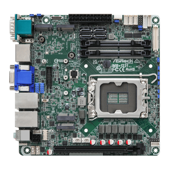
Page 8: Motherboard Layout
1.3 Motherboard Layout... - Page 9 1 : COM Port PWR Setting Jumpers PWR_COM1 (For COM Port1) PWR_COM2 (For COM Port2) 2 : M.2 Key-M Socket (M2_M2) 3 : ESPI Header (ESPI1) 4 : M.2 Key-B Socket (M2_B1) 5 : 24-pin ATX Power Input Connector 6 : SATA3 Connectors (SATA3_1~4) 7 : COM Port PWR Setting Jumper PWR_COM3 (For COM Port3) 8 : SATA Power Output Connector...
-
Page 10: I/O Panel
1.4 I/O Panel COM Port (COM1)* Microphone (Pink) DisplayPort (DP1) USB3.2 Gen2 Ports (USB3_7_8) D-Sub Port (VGA1) USB3.2 Gen2 Ports (USB3_1_2) RJ45 LAN Port (LAN2)** DisplayPort (DP2) RJ45 LAN Port (LAN1)** HDMI Port (HDMI1) Line out (Lime) COM Port (COM2)* * This motherboard supports RS232/422/485 on COM1, 2 ports. -
Page 11: Installation
Chapter 2: Installation This is a Mini-ITX form factor (6.7” x 6.7”) motherboard. Before you install the moth- erboard, study the configuration of your chassis to ensure that the motherboard fits into it. Make sure to unplug the power cord before installing or removing the motherboard. -
Page 12: Installation Of Memory Modules (So-Dimm)
2.3 Installation of Memory Modules (SO-DIMM) This motherboard provides two 260-pin DDR4 (Double Data Rate 4) SO-DIMM slots. 1. The SO-DIMM only fits in one correct orientation. It will cause permanent damage to the motherboard and the SO-DIMM if you force the SO-DIMM into the slot at incorrect orientation. -
Page 14: Expansion Slots
2.4 Expansion Slots There is 1 PCI Express slot, 4 M.2 sockets and 1 SIM socket on this motherboard. PCIE slot: PCIE1 (PCIE 4.0 x16 slot) is used for PCI Express x16 lane width cards*. *Supports riser card x8/x8. M.2 sockets: 1 x M.2 (Key E, 2230) with PCIe x1, USB 2.0 and CNVi for Wireless. -
Page 15: Jumpers Setup
2.5 Jumpers Setup The illustration shows how jumpers are setup. When the jumper cap is placed on pins, the jumper is “Short”. If no jumper cap is placed on pins, the jumper is “Open”. The illustration shows a 3-pin jumper whose pin1 and pin2 are “Short”... - Page 16 CON_LBKLT_CTL Voltage Level 1-2 : 3V Level 2-3 : 5V Level (3-pin BLT_PWM2) (see p.8, No. 17) Panel Power Select (LCD_VCC) 1-2 : LCD_VCC: +3V 2-3 : LCD_VCC: +5V (5-pin PNL_PWR1) 4-5 : LCD_VCC: +12V (see p.8, No. 15) Digital Input / Output Default Value Setting 1-2 : Pull-High 2-3 : Pull-Low (3-pin JGPIO_SET1)
-
Page 17: Onboard Headers And Connectors
2.6 Onboard Headers and Connectors Onboard headers and connectors are NOT jumpers. Do NOT place jumper caps over these headers and connectors. Placing jumper caps over the headers and connectors will cause permanent damage of the motherboard! CPU Fan Connector Please connect the CPU fan cable to the connector and (4-pin CPU_FAN1) - Page 18 RESET (Reset Switch): Connect to the reset switch on the chassis front panel. Press the reset switch to restart the computer if the computer freezes and fails to perform a normal restart. PLED (System Power LED): Connect to the power status indicator on the chassis front panel. The LED is on when the system is operating.
- Page 19 USB 2.0 Headers There are two headers on this motherboard. Each USB 2.0 (9-pin USB2_5_6, USB2_10_11: header can support two ports. see p.8, No. 34) USB 3.2 Gen1 Header There is one header on this Vbus Vbus Vbus IntA_PB_SSRX- motherboard. This USB 3.2 (19-pin USB3_4_9) IntA_PA_SSRX- IntA_PB_SSRX+...
- Page 20 LVDS Panel Connector* Signal Name Signal Name LCD_BLT_VCC LCD_BLT_VCC (40-pin LVDS1) CON_LBKLT_CTL LCD_BLT_VCC CON_LBKLT_EN (see p.8 No. 14) LVDS_B_CLK# LVDS_B_CLK LVDS_B_DATA3 DPLVDD_EN LVDS_B_DATA3# LVDS_B_DATA2# LVDS_B_DATA2 LVDS_B_DATA1 LVDS_B_DATA1# LVDS_B_DATA0# LVDS_B_DATA0 LVDS_A_CLK LVDS_A_CLK# LVDS_A_DATA3# LVDS_A_DATA3 LVDS_A_DATA2 LVDS_A_DATA2# *eDP by pass mode pin definition (switch by BIOS): LVDS_A_DATA1# LVDS_A_DATA1 LVDS_A_DATA0...
- Page 21 4-Pin ATX Power Connector Please connect a DC power supply to this (4-pin DC_4PIN1) connector, or connect the 4-pin (see p.8 No. 31) ATX 12V Power to this connec- tor when using ATX power supply. 1-2 : GND 3-4 : DC Input ATX Power Input Connector This motherboard provides a 24-pin ATX power connector.
-
Page 22: Installation Of Rom Socket
2.7 Installation of ROM Socket * Do not apply force to the actuator cover after ic inserted. * Do not apply force to actuator cover when it is opening over 120 degree, Otherwise, the actuator cover may be broken. * The yellow dot (Pin1) on the ROM must be installed at pin1 position of the socket (white arrow area). -
Page 23: Uefi Setup Utility
Chapter 3: UEFI SETUP UTILITY 3.1 Introduction This section explains how to use the UEFI SETUP UTILITY to configure your system. The UEFI chip on the motherboard stores the UEFI SETUP UTILITY. You may run the UEFI SETUP UTILITY when you start up the computer. Please press <F2>... -
Page 24: Navigation Keys
3.1.2 Navigation Keys Please check the following table for the function description of each navigation key. Navigation Key(s) Function Description Moves cursor left or right to select Screens Moves cursor up or down to select items + / - To change option for the selected items <Enter>... -
Page 25: Advanced Screen
3.3 Advanced Screen In this section, you may set the configurations for the following items: CPU Configu- ration, Chipset Configuration, Storage Configuration, Super IO Configuration, AMT Configuration, ACPI Configuration, USB Configuration and Trusted Computing. Setting wrong values in this section may cause the system to malfunction. -
Page 26: Cpu Configuration
3.3.1 CPU Configuration Intel Hyper Threading Technology Intel Hyper Threading Technology allows multiple threads to run on each core, so that the overall performance on threaded software is improved. Active Processor P-Cores Select the number of cores to enable in each processor package. Active Processor E-Cores Select the number of E-Cores to enable in each processor package. - Page 27 Intel Turbo Boost Technology Use this item to enable or disable Intel Turbo Boost Mode Technology. Turbo Boost Mode allows processor cores to run faster than marked fre- quency in specific conditions. The default value is [Enabled]. CPU Thermal Throttling You may select [Enabled] to enable CPU internal thermal control mechanism to keep the CPU from overheating.
-
Page 28: Chipset Configuration
3.3.2 Chipset Configuration Primary Graphics Adapter This allows you to select [Onboard] or [PCI Express] as the boot graphic adapter priority. The default value is [PCI Express]. Above 4G Decoding Enable or disable 64bit capable Devices to be decoded in Above 4G Ad- dress Space (only if the system supports 64 bit PCI decoding). - Page 29 (F9 load default is also set to ENABLE). Change the setting from [Enable] to [Disable], and then press <F10> to save the setting and restart the sys- tem. Likewise, the default value of Active LVDS is changed to DISABLE (F9 load default is also set to DISABLE) Onboard LAN1 This allows you to enable or disable the Onboard LAN1 feature.
-
Page 30: Storage Configuration
3.3.3 Storage Configuration VMD Configuration This item allows you to enable or disable the Intel VMD support function. SATA Controller(s) Use this item to enable or disable the SATA Controller feature. SATA Mode Selection Use this to select SATA mode. The default value is [AHCI Mode]. AHCI (Advanced Host Controller Interface) supports NCQ and other new features that will improve SATA disk perfor- mance but IDE mode does not have these advantages. -
Page 31: Super Io Configuration
3.3.4 Super IO Configuration COM1 Configuration Use this to set parameters of COM1. Type Select Use this to select COM1 port type: [RS232], [RS422] or [RS485]. COM2 Configuration Use this to set parameters of COM2. Type Select Use this to select COM2 port type: [RS232], [RS422] or [RS485]. COM3 Configuration Use this to set parameters of COM3. -
Page 32: Amt Configuration
3.3.5 AMT Technology USB Provisioning of AMT Use this to enable or disable AMT USB Provisioning. The default is [Dis- abled]. MAC Pass Through Use this to enable or disable MAC Pass Through. The default is [Disabled]. Activate Remote Assistance Process Trigger CIRA boot. - Page 33 OCR PBA Boot Use this to enable or disable One Click Recovery PBA Boot. The default is [Enabled]. OCR Windows Recovery Boot Use this to enable or disable One Click Recovery Windows Recovery Boot. The default is [Enabled]. OCR Disable Secure Boot Use this to allows CSME to request Secure Boot to be disabled for One Click Recovery.
-
Page 34: Acpi Configuration
3.3.6 ACPI Configuration Suspend to RAM Use this item to select whether to auto-detect or disable the Suspend-to- RAM feature. Select [Auto] will enable this feature if the OS supports it. PCIE Devices Power On Use this item to enable or disable PCIE devices to turn on the system from the power-soft-off mode. -
Page 35: Usb Configuration
3.3.7 USB Configuration USB Power Control Use this option to control USB power. M.2 Key_B USB Configuration Enable or disable M.2 Key_B USB Configuration. -
Page 36: Trusted Computing
3.3.8 Trusted Computing Security Device Support Enable or disable BIOS support for security device. -
Page 37: Hardware Health Event Monitoring Screen
3.4 Hardware Health Event Monitoring Screen In this section, it allows you to monitor the status of the hardware on your system, including the parameters of the CPU temperature, motherboard temperature, CPU fan speed, chassis fan speed, and the critical voltage. CPU_FAN1 Setting This allows you to set CPU fan 1’s speed. -
Page 38: Security Screen
3.5 Security Screen In this section, you may set, change or clear the supervisor/user password for the system. Supervisor Password Set or change the password for the administrator account. Only the ad- ministrator has authority to change the settings in the UEFI Setup Utility. Leave it blank and press enter to remove the password. -
Page 39: Boot Screen
3.6 Boot Screen In this section, it will display the available devices on your system for you to config- ure the boot settings and the boot priority. Boot From Onboard LAN Use this item to enable or disable the Boot From Onboard LAN feature. Setup Prompt Timeout This shows the number of seconds to wait for setup activation key. -
Page 40: Exit Screen
3.7 Exit Screen Save Changes and Exit When you select this option, it will pop-out the following message, “Save configuration changes and exit setup?” Select [OK] to save the changes and exit the UEFI SETUP UTILITY. Discard Changes and Exit When you select this option, it will pop-out the following message, “Discard changes and exit setup?”...
Need help?
Do you have a question about the IMB-1231 and is the answer not in the manual?
Questions and answers