Table of Contents
Advertisement
Quick Links
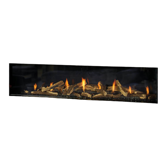
CV72E-12 Direct Vent
New York 72
http://bit.ly/2yIGUao
STYLE
Single sided
Warning
Fire or explosion Hazard
failure to follow safety warnings exactly could result in serious
injury, death, or property damage.
- Do not store or use gasoline or other flammable vapors and liquids in the vicinity of this or any
other appliance.
- WHAT TO DO IF YOU SMELL GAS
•
Do not try to light any appliance.
• Do not touch any electrical switch: do not use any phone in your building.
Leave the building immediately.
• Immediately call your gas supplier from a neighbour's phone. Follow the gas supplier's
instructions.
• If you cannot reach your gas supplier, call the fire department.
- Installation and service must be performed by a qualified installer, service agency or the gas supplier.
Tested by:
Certified to/Certifié pour: CSA 2.17-2017
FPI FIREPLACE PRODUCTS INTERNATIONAL LTD. 6988 Venture St., Delta, BC Canada, V4G 1H4
920-608
City Series
®
MODEL
CV72E-NG12 / CV72E-LP12
ANSI Z21.88:19
CSA 2.33:19
Installer: Please complete the details on the back cover and leave
this manual with the homeowner.
Homeowner: Please keep these instructions for future reference.
Owners &
Installation Manual
www.regency-fire.com
09.20.22
Advertisement
Table of Contents

Subscribe to Our Youtube Channel
Related Manuals for Regency City CV72E-12


Summary of Contents for Regency City CV72E-12
- Page 1 City Series ® Owners & CV72E-12 Direct Vent Installation Manual New York 72 http://bit.ly/2yIGUao www.regency-fire.com STYLE MODEL Single sided CV72E-NG12 / CV72E-LP12 Warning Fire or explosion Hazard failure to follow safety warnings exactly could result in serious injury, death, or property damage.
- Page 2 To the New Owner: Congratulations! You are the owner of a state-of-the-art Gas Fireplace by REGENCY . The City Series are hand crafted appliances and have ® been designed to provide you with all the warmth and charm of a wood fireplace at the flick of a switch. The CV72E City Series have been approved by Intertek for both safety and efficiency.
- Page 3 MANUFACTURED MOBILE HOME REQUIREMENTS INFORMATION FOR MOBILE/MANUFACTURED HOMES AFTER FIRST SALE This Regency product has been tested and listed by Intertek as a Direct Vent Wall Furnace to the following standards: to Vented Gas ® Fireplace Heaters ANSI Z21.88 • CSA 2.33 and Gas-fired Appliances for Use at High Altitudes CSA 2.17.
- Page 4 WARNING CARBON MONOXIDE POISONING HAZARD Failure to follow the steps outlined below for each appliance connected to the venting system being placed into operation could result in carbon monoxide poisoning or death. The following steps shall be followed for each appliance connected to the venting system being placed into operation, while all other appliances connected to the venting system are not in operation: 1.
-
Page 5: Table Of Contents
table of contents Horizontal Venting with Two (2) 90 Elbows ........56 Owner's information Horizontal Venting with Three (3) 90 Elbows ........ 56 Venting Introduction ..............57 Copy of Safety Decal ..............6 Venting Arrangement for Horizontal Terminations ......57 Decal location ................ -
Page 6: Copy Of Safety Decal
The safety label is located on the front inside base of the unit, visible when the outer front panel is removed. NOTE: Regency units are constantly being improved. Check the label on the unit and if there is a ®... -
Page 7: Dimensions
dimensions Dimensions 3 3 8 8 1 1 1 1 1 1 6 6 " " 3 3 8 8 1 1 1 1 1 1 6 6 " " 9 9 8 8 3 3 m m m m 9 9 8 8 3 3 m m m m Ø... -
Page 8: Gas Connection - Back Of Unit
installation Gas Connection - Back of Unit removable knockouts 3-7/8" 17" 5" 5" 5" 17" 36-1/4" 36-1/4" Gas Connection - Bottom of Unit Opening at unit base Gas Valve Back of Unit 14-1/2" Front of Unit Gas Connection - Side of Unit tooltip oltip Back of Unit... -
Page 9: Electrical Connection - Bottom Of Unit
installation Electrical Connection - Bottom of Unit Front of Unit 77-7/16" Receptacle 8" Back of Unit Electrical opening Electrical Connection - Side of Unit Front of Back of unit unit 4" 2-3/4" City Series CV72E-12 |... -
Page 10: Gas Installation Checklist
This general checklist does not contain all pertinent installation details or specifics and does not supersede the guidelines in this manual. Your Regency dealer/installer should use it in conjunction with manual instructions. Please follow all local codes and jurisdictions in authority. - Page 11 REGENCY GAS INSTALLATION CHECKLIST Finishing If applicable, is only noncombustible material installed in the noncombustible areas? Do clearances meet installation and manual requirements? Do the mantels and/or projections comply with the installation manual? If applicable, was the solid fuel fireplace warning plate installed?
-
Page 12: Important Message
owner's information Important Message WE RECOMMEND REMOVING THE CHILDREN AND ADULTS SHOULD SAVE THESE INSTRUCTIONS GLASS WITH THE GLASS VACUUM BE ALERTED TO THE HAZARDS OF H O L D E R S S U P P L I E D B Y T H E HIGH SURFACE TEMPERATURES, City Line Direct Vent Fireplaces must be installed in MANUFACTURER. -
Page 13: First Fire
owner's information First Fire Normal Operating Sounds Of Gas Appliances The FIRST FIRE in your fireplace is part of the paint curing process. To ensure the paint is prop- It is possible that you will hear some sounds from erly cured, it is recommended you burn your your gas appliance. -
Page 14: Lighting Procedure
owner's information Lighting Procedure The remote control system supplied has several options The first try for ignition will last approximately 60 seconds. If there is no flame ignition (rectification), the board will stop sparking for ap- for starting/operating the appliance using the battery proximately 35 seconds. -
Page 15: Copy Of The Lighting Plate Instructions
owner's information Copy of the Lighting Plate Instructions FOR YOUR SAFETY READ BEFORE LIGHTING POUR VOTRE SÉCURITÉ – À LIRE AVANT LA MISE EN MARCHE WARNING: If you do not follow these instructions exactly, a fire or explosion may result causing property damage, personal injury or loss of life. -
Page 16: Proflame Ii Remote Control Operating Instructions
owner's information Proflame II Remote Control Operating Instructions The transmitter and IFC are radio frequency devices. The Proflame Transmitter 2 is an integrated part of the Proflame 2 System, which consists of these elements: • Proflame 2 Transmitter, in conjunction with •... - Page 17 owner's information Temperature indication Display Remote‑Flame Control With the system in the "OFF" position, press the Thermostat Key and The Proflame has six (6) flame levels. With the system on, and the flame the Mode Key at the same time. Look at the LCD screen on the transmit- level at the maximum in the appliance, pressing the Down Arrow Key ter to verify that a C or F is visible to the right of the room temperature once will reduce the flame height by one step until the flame is turned off.
- Page 18 owner's information Smart Thermostat (Transmitter Operation) Remote dimmer control (Light)** The auxiliary function controls the AUX power outlet by the dimmable The Smart Thermostat function adjusts the flame height in accordance light control. To activate this function use the Mode Key (fig. 1) to index to the difference between the set point temperature and the actual room to the AUX icon (fig.
- Page 19 owner's information Continuous Pilot/Intermittent Pilot (CPI/IPI) selection 5. "Clr" will remove a mode—use the up or down arrow while holding down ON/OFF and MODE (mode icon will disappear once removed). Note: Power vent models do not have a Continuous 6. Use the "MODE" button to move to the next function. Pilot option.
- Page 20 owner's information Proflame II Battery Holder Battery Replacement & Battery Pack up if 120 Volt Power is lost IMPORTANT Battery Holder Battery Replacement & Battery Back up if 120 volt power is lost Non-Power Vent Model: Install the 4 AA batteries during power outages to run the main burner. However, the lights will not operate Power Vent Model: This appliance will not operate if 120 volt power is lost within the home.
-
Page 21: Wifi Dongle Installation (Optional)
CV72E-12 owner's information WIFI Dongle Installation Instructions WIFI Dongle Installation (Optional) 1. Remove the outer panels and safety glass – see manual. 5. Reverse steps 1 and 2 to reinstall the IFC cover. 6. Apply Velcro strips to the bottom of the dongle and to the side of the bracket 2. -
Page 22: Glass Barrier Removal
owner's information Glass Barrier Removal OWNERS MANUAL Glass safety barrier removal Glass barrier removal video 1. Prepare a soft, scratch resistant surface to place the 70-3/8 " x 15-1/4" glass (i.e. large sheet or clean drop cloth). 2. Attach the vacuum clamps to the glass as shown. Press the vacuum clamps against the glass, then close the clamps while maintaining pressure on the glass. -
Page 23: Inner Glass Panel (Firebox Glass) Installation / Removal
owner's information Inner Glass Panel (firebox glass) Installation / Removal Note: glass panels must be installed to operate fireplace 3. From the front inside lower panel of the unit--pivot the 3 glass supports into upright position as shown below. WARNING: GLASS HANDLING We recommend using the glass vacuum holders supplied by the manufac- turer. - Page 24 owner's information 5. Pull the 3 lower glass gasket pads forward to release the glass. Gasket pad Push down on levers to lower glass panel 6. Support the glass with one hand and open the 9 lower clamps. 8. Carefully lean glass forward onto supports. Glass panel--leaning on supports NOTE: The firebox glass may remain propped on the glass supports to clean the interior surface.
-
Page 25: Optional Barrier Glass Stoppers Installation / Removal
owner's information Optional Barrier Glass Stoppers Installation / Removal There are 2 optional stoppers included in the manual pack which provide additional support to the glass barrier, if desired--install the stoppers prior to installation of the barrier glass. 1. If already installed, remove the side panel by pulling off and lifting out. 3. -
Page 26: Bulb Replacement
Regency Part# 911-208 Oven Lamp Assembly G9 120V/25W Regency Part# 911-072 Replacement Bulb G9 120 Volt/25 watt t t o o o o l l t t i i p p Light are located behind the front face of the unit 3. -
Page 27: Maintenance Instructions
For relighting, refer to lighting instructions. Keep Continuous condensation can cause corrosion Regency dealer only. Replacement glass is shipped the burner and control compartment clean by of caps, pipe, and fittings. It may be caused already installed into the door frame. -
Page 28: Installer's Information
installer's information MA Code - CO Detector (for the State of Massachusetts only) 5.08: Modifications to NFPA-54, Chapter 10 (2) Revise 10.8.3 by adding the following additional requirements: (a) For all side wall horizontally vented gas fueled equipment installed in every dwelling, building or structure used in whole or in part for residential purposes, including those owned or operated by the Commonwealth and where the side wall exhaust vent termination is less than seven (7) feet above finished grade in the area of the venting, including but not limited to decks and porches, the following requirements shall be satisfied:... -
Page 29: General Safety Information
requirements installer's information General Safety Information Installation Checklist Before leaving this unit with the customer, the installer must ensure that the appliance is firing correctly and operation fully explained to customer. 1. The appliance installation must conform with 1. Locate appliance. Refer to the following local codes or, in the absence of local codes, with sections: This includes:... -
Page 30: Locating Your Gas Fireplace
installer's information Locating Your Gas Fireplace 1. When selecting a location for your fireplace, ensure that the clearances are met. 2. The appliance must be installed on a flat, solid, continuous surface For example a wood, metal or concrete floor or in a raised (on the wall) application. -
Page 31: Unit Assembly Prior To Installation
requirements installer's information Unit Assembly Prior to Installation Before you Start - Removing the Unit from the Pallet Remove the screws securing the unit to the pallet Due to the size and weight (529 pounds shipping weight) of the CV72E--lifting and moving the unit will require 4 people. - Page 32 installer's information Access Panel Removal The front access panels (x3) may be removed for ease of hooking up gas and electrical--prior to finishing. Once complete ensure that the access panel is reinstalled prior to any finishing. See locations in diagram to the right. Note: Once the finished material is installed, these access panels are no longer accessible.
-
Page 33: Ventilation Openings (Bay Installation)
Ventilation Openings Regency's patented Cool Wall system releases warmth at ceiling level. This system reduces excessive radiant heat in front of the fireplace so you can enjoy your fireplace more often. • Design your own chase vent solution to suit your home •... -
Page 34: Chase Enclosure
Min 42.25” (1073 mm) installation Chase Enclosure Opening for vent When choosing to install the ventilation openings from the front or both sides, The top of the ventilation opening cannot be any lower than 0-2" (51mm) 4”-4.5” from the top of the chase enclosure for all installations. Minimum height of enclosure from base of appliance is 87"... -
Page 35: Clearances
installation Clearances The clearances listed below are minimum distances unless otherwise stated: A major cause of chimney related fires is failure to maintain required clearances (air space) to combustible materials. It is of the greatest importance that this fireplace and vent system be installed only in accordance with these instructions. Flue Clearances to Combustibles Clearance: single sided Dimension... -
Page 36: Mantel Clearances
installation Mantel Clearances Combustible mantel clearances from top of front facing are shown in the diagram on the right. 1/2" (13mm) Drywall, wood, wood panel, etc. 12" (305mm) 9” (229mm) 5-1/8" (130mm) To Bottom of Top of Fireplace Fireplace 15-1/16" Opening Opening (382mm) -
Page 37: Framing Dimensions
installation Framing Dimensions NOTE: Framing may be constructed of combustible material (ie. 2 x 4)and does not require steel studs. Framing Description CV72E Dimensions Framing Height 51" (1295mm) Framing Width 78" (1981mm) Framing Depth 20-5/8" (524mm) Minimum Height to Combustibles 87"(2210mm) Corner Wall Depth 82-1/8"... -
Page 38: Chase Vent Installation
CITY SERIES installation Chase Vent Installation CV72E CHASE VENT INSTALLATION Framed Opening must be between 5” and 5.5” tall, and at least 74.25” wide to accomodate the Chase vent. The top of the chase vent opening must be 2” or less from the top of the chase enclosure. Min 74.25”... - Page 39 CITY SERIES installation Finish edges of drywall with trim or corner bead. Edge nish must not decrease opening area below 306in (4.25”x72”) City Series CV72E-12 | 919-830b 01.23.18...
- Page 40 CITY SERIES installation Frame opening for vent Screw Chase vent to Framing Use at least 4 sets of screws (See Vent Framing Clearances Page) to keep the vent at against frami Drywall Frame wall with nishing material If necessary, mark where the Cut hole in nishing material chase vent is located before around inside of chase vent.
-
Page 41: Extended View Panel Installation
installation CITY SERIES Extended View Panel Installation EXTENDED VIEW PANEL INSTALLATION 1. Construct the sealed rear enclosure to specified width shown below 4. Move unit into framed opening at desired height and level unit on all and desired height (see unit manual for detailed framing instructions). sides. - Page 42 CITY SERIES installation 7. Install venting before proceeding (see unit manual for details). 10. Install inner panels (refer to instructions in unit manual). Install inner panels Install venting 11. Install glass panels onto base panels (glass panels are secured in place with magnets).
-
Page 43: Wall Board/Drywall Installation
installation Wall Board/Drywall Installation WARNING! Risk of Fire! Comply with all minimum clearances to combustibles as specified. Finishing Instructions It is important to follow the framing and finishing instructions to ensure proper placement of fireplace into the surrounding framing/finishing materials. Wall board materials 1/2 in. -
Page 44: Framing And Finishing Inset Installations
installation Framing and Finishing Inset Installations Drywall Lip - Bottom and Sides (Optional) 1. Frame in the enclosure for the unit with framing material If desired the finishing lip on both sides and bottom may be removed. Re- Note: When constructing the framed opening ensure there is access to install move the 2 screws on each side to remove the side drywall lip and loosen the gas lines,electrical. -
Page 45: Typical Installations
288in using a reveal using a reveal Chase Vent opening to vent the chase Chase Vent opening to vent the chase Shown with Regency Shown with Regency Chase Vent 666-991 Chase Vent 666-991 Header Stud Header Stud Max 5 ”... -
Page 46: Typical Installations
FLUSH TV WITH HEARTH Maximum TV Recess Flush TV with Hearth Max 2” To Top of Enclosure 288in Chase Vent opening Shown with Regency Chase Vent 666-532 Max 4 ” TV recess with drywall up against unit Header Stud Max 5 ”... -
Page 47: Finishing
installation Finishing CV72 Finishing Flush Install Example - Front edge of side liner panels must not be covered by nishing material or - Loosen screws using supplied O set removal of the Firebox Glass will not be Screwdriver and remove bottom and - Finish up to trim on all 4 sides possible side trim pieces... -
Page 48: Exterior Vent Termination Locations
installation Exterior Vent Termination Locations Minimum Clearance Requirements Canada Clearance above grade, veranda, porch, deck, or balcony 12"(30cm) 12"(30cm) Clearance to window or door that may be opened 12"(30cm) 9" (23cm) Clearance to permanently closed window Vertical clearance to ventilated soffit located above the terminal within a horizontal distance of 2 feet (61cm) 29"(74cm) 29"(74cm) from the center line of the terminal (check with the local code) -
Page 49: 5" X 8" Rigid Pipe Cross Reference Chart
Note: Olympia Venis DV venting is only approved for certain models. See list of approved models in cross-reference chart. Components from different Manufacturers may not be mixed. Not all rigid pipe components are available directly from Regency. Note: Olympia Ventis DV venting is only approved for certain models. See list of approved models in cross-reference chart. - Page 50 TM-5ST14 Snorkel Termination 36" 58DVA-SNK36* TM-5ST36 Restrictor Disk Colinear Flex Connectors * Not available from Regency 946-604/P Simpson Direct Vent or Astro Cap -Vent Guard (Optional) 946-623/P AstroCap XL Horizontal Cap 770-994 Rigid Pipe Adaptor (Must use with all rigid piping)
-
Page 51: Wall Mount On / Off Switch And Battery Holer Installation
installation Wall Mount On / Off Switch and Battery Holder Installation Required for all installations IMPORTANT INSTALLATION NOTE: The battery holder must be placed inside the supplied (low voltage) junction type wall box and installed into the wall only. DO NOT INSTALL WITHIN THE CONFINES OF THE FIREPLACE SWITCH MUST BE ACCESSIBLE Battery Holder Installation 1. - Page 52 installation Proflame Wall Mount Transmitter WALL MOUNTING The Proflame remote control/transmitter is supplied with an adapter for wall mounting.Install the controller 59" (1.5m) above the floor level, well away from heat sources, kitchens, doors or windows. Metalllic structures or radio interferences can reduce the operative distance of the device.
-
Page 53: Vent Restrictor Position
installation Vent Restrictor Position Vent restriction is required for certain venting installations, see the diagrams in the "Venting Arrangements" section to determine if they are required for your installation. The Vent Restrictor plate is installed on the appliance at Set 0. To set the vent restriction as indicated in the venting arrangements diagrams, refer to the following instructions;... -
Page 54: Horizontal Terminations - Flex Vent 5" X 8
9) S.S. screws #8 x 1-1/2” drill point 10) vinyl siding standoff Notes: 1. Liner sections should be continuous without any joints or seams. 2. Only Flex pipe purchased from Regency may be used ® for Flex installations 3. Horizontal vent must be supported every 3 feet. Vent Guard - if required* 4. -
Page 55: Horizontal Terminations - Rigid Pipe 5" X 8
installation Horizontal Terminations - " Rigid Pipe 5" x 8 The minimum components required for a basic horizontal termination are: Horizontal Termination Cap Rigid Pipe Adaptor (770-994) Wall Thimble Length of pipe to suit wall thickness (see chart) Horizontal Termination Cap Wall thickness is measured from the back standoffs to the inside mounting surface of termination cap. -
Page 56: Horizontal Terminations - Rigid Pipe 5" X 8
installation Horizontal Terminations - " Rigid Pipe 5" x 8 The diagrams below show examples of horizontal termination arrangements using one, two, or three 90 elbows (two 45 elbows equal one 90 elbow). 1. A maximum of three 90 elbows are permitted. 2. -
Page 57: Venting Introduction
Refer to the "Vent Restrictor Position" section for details on how to change the vent restrictor from the factory setting of Set 0 to Set 2 if required. Note: For horizontal terminations the Regency Direct Vent Flex System may be used for installations with a maximum continuous vent length of up to 10 feet. -
Page 58: Horizontal Termination 5" X 8" Venting (Flex Vent Systems)
installation Horizontal Termination 5" NOTE: Horizontal sections must be sup- ASTROCAP XL ported at intervals not exceeding 3 x 8" Venting (Flex Vent DIMENSIONS (946-623/P) feet (0.9 meter). (Flame picture and Systems) performance will be affected by sags in the liner). 4. -
Page 59: Horizontal Termination - 5" X 8" Venting (Rigid Vent Systems)
installation Horizontal Termination - 5" Horizontal runs of vent must be supported Below Grade Snorkel Installation every 3 feet (0.9meter). Wall straps are avail- If the snorkel termination must be installed below x 8" Venting (Rigid Vent able for this purpose. grade, i.e. -
Page 60: Vertical Terminations - Rigid/Flex Pipe 5" X 8
installation Vertical Terminations - " Rigid/Flex Pipe 5" x 8 The minimum components required for a basic vertical termination are: Vertical Terminal Vertical Termination Cap Rigid Pipe Adaptor (770-994) Ceiling Firestop Flashing Storm Collar Storm Collar Length of pipes to suit wall thickness & vent run (see chart) Flashing Galvanized pipe is desirable above the roofline due to its higher... -
Page 61: Vertical Terminations - Rigid/Flex Pipe 5" X 8
installation Vertical Terminations - " Rigid/Flex Pipe 5" x 8 • Two 45 elbows equal to one 90 elbow. Maximum of six 45 elbows allowed. • Vent must be supported at offsets. • Minimum distance between elbows is 1 ft. (305mm). •... -
Page 62: Venting Arrangement For Vertical Terminations - Straight Vertical
installation Venting Arrangement for Vertical Terminations - Straight Vertical Venting and/or with a Max. of Two (2) 90 Elbows (1 - 90 2 - 45 Horizontal (Feet) The shaded area in the diagram shows all allowable combinations of straight vertical and offset to vertical terminations, using two 1 1 4 4 1 1 8 8 1 1 0 0... -
Page 63: Vertical Termination (Rigid Vent Systems)
installation (Rigid Vertical Termination 4) Assemble the desired lengths of pipe and elbows. Ensure that all pipes and elbow connections are Vent Systems) in the fully twist-locked position and sealed. Note: A top clearance of 3"(76mm) and Note: side bottom clearance of 2" (51mm) For best results and optimum performance must be maintained;... -
Page 64: Vertical Terminations - Vertical Flex Vent Kit (Part #946-772)
Termination Cap installation Storm Collar Vertical Termination Flashing Vertical Terminations - Vertical Flex Vent Kit (Part #946-772) 5" (127 mm) x 8" (203 mm) Venting - Vertical Flex Vent Kit for North America (Part #946-772) Roof support Vertical Flex Vent Kit includes: Firestop spacer to prevent debris from falling into the •... - Page 65 Vertical Termination installation 5" (127 mm) x 8" (203 mm) Venting - Vertical Flex Vent Kit for North America installation (Part #946-772) 13. Slide the finished length up towards the flashing ensuring the 13. Slide the finished length up towards the flashing ensuring the length of length of pipe is a minimum of 2 feet (0.61 m) measured from installation Termination Cap...
-
Page 66: Vertical Flex Extension Kit (Part # 946-769)
installation Vertical Flex Extension Kit for North America Part #946-769 Vertical Flex Extension Kit (Part # 946-769) 20 foot (6.1 m) flex pipe extension Vertical Flex Extension Kit includes: 5" (127 mm) inner pipe - 20 ft. (6.1 m) • 20 ft. flex pipe (inner & outer) with 10 spacers •... -
Page 67: Ceiling Firestop / Firestop Spacer (Part # 946-770)
installation Ceiling Firestop/Firestop Spacer (North America) VERTICAL FLUE EXTENSION KIT (APPROVED MODELS) Ceiling Firestop / Firestop Spacer (Part # 946-770) Part #946-770 (PART # 946-756) Used in conjunction with the 946-772 Vertical Flex Kit and 946-769 VERTICAL FLUE EXTENSION KIT (APPROVED MODELS) 11"... -
Page 68: Heatwave Deflector + Heatwave Venting Installation
installation Heatwave Deflector + Heatwave Venting Installation NOTE: Install the Heatwave venting to the unit before moving unit into framing to allow access to the back screws. 5. Connect the flex pipe to the adaptor with 3 screws. 1. Remove the deflector from the top of the unit by removing 4 screws. 2. -
Page 69: System Data
(9.37 KW) CV72E LP SYSTEM DATA Max. Supply Pressure 14"WC (3.45 Kpa) Note: If you have an incorrect flame pattern, contact your Regency Min. Supply Pressure 11" WC (2.73 kpa) ® dealer for further instructions. Manifold Pressure 10" WC (2.49 kpa) -
Page 70: Wiring The Unit
installation Wiring the Unit The wiring for the unit should be completed before any finishing material is installed. 1. Remove the right side and front right access panel--see access panel removal instructions in this manual. 2. Loosen 2 screws in locations shown below. 3. -
Page 71: Non-Pv Wiring Diagram
installation Non-PV Wiring Diagram While the burner does not require a 120 V A.C. power supply, it is highly recommended as a primary power source. Batteries (4 AA) should be used as a secondary power source only. • Label all wires prior to disconnection when servicing controls. Wiring errors can cause improper and dangerous operation. -
Page 72: Vent Chart For Power Vent Only - Horizontal Terminations Inline Horizontal Vent Chart
installation-power vent Vent Chart for Power Vent Only CV72EPV/CB72EPVCB40EPV/CC40EPV/CV40EPV/CV60EPV Horizontal Terminations - Inline Horizontal Vent Chart Inline Power Vent Vertical or Hortizontal Installation Instructions This section is for the Power Vent System installation. For a detailed installation information, refer Power Vent System installation instructions that comes with the Power Vent Kit. -
Page 73: Vent Chart For Power Vent Only - Horizontal Terminations
installation-power vent Vent Chart for Power Vent Only Horizontal Terminations - End of Line Horizontal Vent Chart For the complete Power Vent installation, refer the Power Vent System installation instruction in Power vent system Kit End Line Power Vent Kit # 946-535 RIGID PIPE: MUST USE RIGID PIPE ADAPTOR 770-994 AND 946-606 PIPE REDUCER TO 4"... -
Page 74: Inner Glass Panel (Firebox Glass) Installation / Removal
installation Inner Glass Panel (Firebox Glass) Installation / Removal To watch the glass installation video click here: http://youtu.be/DsPbbiLIbdU Note: glass panels must be installed to operate fireplace 3. From the front inside lower panel of the unit--pivot the 3 glass supports into upright position as shown below. - Page 75 installation 5. Support the glass with one hand and open the 9 lower clamps.-- Push down on levers to lower glass panel 8. Carefully lean glass forward onto supports. Lower clamps (x9) in open position 6. Pull the 3 lower glass gasket pads forward to release the glass. Gasket pad Glass panel--leaning on supports NOTE: The firebox glass may remain propped on the glass supports to clean...
-
Page 76: Optional Barrier Glass Stoppers Installation / Removal
installation Optional Barrier Glass Stoppers Installation / Removal There are 2 optional stoppers included in the manual pack which provide additional support to the glass barrier, if desired--install the stoppers prior to installation of the barrier glass. 1. If already installed, remove the side panel by pulling off and lifting out. 3. -
Page 77: Lp Conversion Instructions
CITY SERIES installation CONVERSION FROM NG TO LP LP Conversion Instructions CV72E-11 using SIT 885 NOVA Gas Valve THIS CONVERSION MUST BE DONE BY A QUALIFIED GAS FITTER IF IN DOUBT DO NOT DO THIS CONVERSION! WARNING 6. Disconnect the Cable coming from the Pressure Regulator Motor. This conversion kit shall be installed by a qualified ser- vice agency in accordance with the manufacturer’s in- Cable from motor... - Page 78 installation CITY SERIES tooltip 12. Bend the arm of the aeration lever bracket up from 90° to straighten and tooltip release aeration lever (lever will come with the burner). Bracket Aeration lever 13. Loosen 8 screws in locations shown below (2 at front and 2 at rear)—slide burner to the left away from the orifice and lift out.
-
Page 79: Bulb Replacement
Regency Part# 911-208 Oven Lamp Assembly G9 120V/25W Regency Part# 911-072 Replacement Bulb G9 120 Volt/25 watt t t o o o o l l t t i i p p Light are located behind the front face of the unit 3. -
Page 80: Cv72E Painted Panel Installation
installation CITY SERIES CV72E Painted Panel Installation Inner Panels Outer Panels tooltip CV72E INNER PANELS CV72E OUTER PANELS The CV72E may be equipped with optional steel inner panels. 1. Install 3 front outer panels as shown below. CV72E - 5 outer panels and 10 inner panels. tooltip Turn off gas and power to unit and allow to cool to room temperature. -
Page 81: Enamel Panel Installation
installation CITY SERIES Enamel Panel Installation CV72E ENAMEL PANEL INSTALLATION Black Enamel Panels — Handling Instructions • Black Enamel panels must be inspected for scratches and dimples prior to installation. All claims to be recorded at this time. Claims for damage after installation will not receive consideration. •... -
Page 82: Glass Panel Installation
installation CITY SERIES Glass Panel Installation CV72E GLASS PANEL INSTALLATION 1. Turn off power and gas to unit and allow to cool to room temperature. 6. Install two back panel brackets in between the back wall and the burner Remove the safety glass and fi rebox glass — see manual for instructions. tray. - Page 83 CITY SERIES installation 11. Secure side panel 9 with one screw on the top bracket as shown. 16. Install side outer panel (14) by manoeuvering the panel between the wall and the barrier stopper bracket as shown below. Repeat on other 12.
-
Page 84: Burner And Firebox Media Options
installation Burner and Firebox Media Options Spread the media evenly over the burner. Ensure the glass/stones do not overlap excessively as this will affect the flame pattern. IMPORTANT NOTE: Only the supplied approved media are to be used with these fireplaces. Use of any other type of glass or stones can alter the unit's performance. Any damage caused by the use of any unapproved glass or stones will not be covered under warranty. -
Page 85: Optional Driftwood Log Set Installation
installation CITY SERIES 72 Optional Driftwood Log Set Installation CITY SERIES 72 - LOG INSTALLATION Read the instructions below carefully and refer to the images. If the logs are broken do not use the unit until they are replaced. Broken logs can interfere with pilot operation. Improper positioning of the logs may create carbon build-up and can alter the unit's performance which is not covered under warranty. - Page 86 CITY SERIES 72 installation 6. Place Log 1 behind the burner. Log 1 will rest on the pilot hood and 2 10 . The left end of Log 4 should also sit 2" from the edge of the panel center log guides. Line up the knot on the top of the log with the center as shown below.
- Page 87 CITY SERIES 72 installation 13. Install Log 7 on the diagonal--line up the left end of Log 7 with the 4th Do not completely cover side secondary air inlets vertical line from the right on the front of the burner as shown below. Keep front secondary air inlets clear Correct Black Coal placement 16.
- Page 88 CITY SERIES 72 installation 19. Install Log 12--line up the pin locator on Log 12 with the pin on Log 3 21. Install Log 14--place one end of Log 14 on the rest on Log 8 and the and rest the other end of Log 12 on the rest on Log 8 as shown below. opposite end on the back edge of the burner as shown below.
-
Page 89: Optional Birch Wood Log Set Installation
CITY SERIES 72 installation CITY SERIES 72 - LOG INSTALLATION Optional Birch Wood Log Set Installation Read the instructions below carefully and refer to the images. If the logs are broken do not use the unit until they are replaced. Broken logs can interfere with pilot operation. - Page 90 CITY SERIES 72 installation 6. Place Log 1 behind the burner. Log 1 will rest on the pilot hood and 2 10 . The left end of Log 4 should also sit 2" from the edge of the front panel. center log guides.
- Page 91 installation CITY SERIES 72 13. Install Log 7 on the diagonal--line up the left end of Log 7 with the 4th 16. Install Log 9--line up the pin locator on Log 9 with the pin on Log 1 vertical line from the right on the front of the burner as shown below. and rest the other end of Log 9 on the rest on Log 4 as shown below.
- Page 92 installation CITY SERIES 72 19. Install Log 12--line up the pin locator on Log 12 with the pin on Log 3 21. Install Log 14--place one end of Log 14 on the rest on Log 8 and and rest the other end of Log 12 on the rest on Log 8 as shown below. the opposite end on the back edge of the burner as shown below.
-
Page 93: Optional Splitwood Log Set Installation
installation CITY SERIES 72 Optional Splitwood Log Set Installation CITY SERIES 72 - LOG INSTALLATION Read the instructions below carefully and refer to the images. If the logs are broken do not use the unit until they are replaced. Broken logs can interfere with pilot operation. Improper positioning of the logs may create carbon build-up and can alter the unit's performance which is not covered under warranty. - Page 94 installation CITY SERIES 72 6. Place Log 1 behind the burner. Log 1 will rest on the pilot hood and 10 . The left end of Log 4 should also sit 2" from the edge of the panel 2 center log guides. Line up the log with the center of the pilot hood as shown below.
- Page 95 CITY SERIES 72 installation 16. Install Log 9--line up the pin locator on Log 9 with the pin on Log 1 and rest the other end of Log 9 on the rest on Log 4 as shown below. 14. Install Log 8 - the left end of the log should sit 1" from the edge of the panel.
- Page 96 installation CITY SERIES 72 19. Install Log 12--line up the pin locator on Log 12 with the pin on Log 3 21. Install Log 14--place one end of Log 14 on the rest on Log 8 and the and rest the other end of Log 12 on the rest on Log 8 as shown below. opposite end on the back edge of the burner as shown below.
-
Page 97: Glass Barrier Installation
installation Glass Barrier Installation OWNERS/INSTALLATION MANUAL Glass barrier removal video Glass barrier installation 1. Ensure fireplace is operating properly and all firebox glass, and liner panels are installed prior to installing the glass safety barrier. 2. Remove the protective peel from the glass safety barrier and clean the inner surface. Identify the hooks on the glass safety barrier, these indicate the inner surface. -
Page 98: Glass Barrier Adjustment
installation Glass Barrier Adjustment Glass barrier adjustment If glass isn’t hanging straight, use a phillips screwdriver to adjust the angle. Clockwise = angles barrier out toward you Counter clockwise = angles barrier in towards the unit. Slide the screwdriver straight up at the two indicator slots. | City Series CV72E-12... -
Page 99: Aeration Adjustment
operating instructions Aeration Adjustment 4. Adjust aeration accordingly. Pushing lever in -- closes the air shutter. The burner aeration is factory set but may need adjusting due to either the Pulling the lever outward -- opens the air shutter. local gas supply or altitude. Open the air shutter for a blue flame or close for a more yellow flame. -
Page 100: Maintenance Instructions
& reinstalled in accordance with the Regency dealer only. Replacement glass is shipped Log Replacement manufacturer's instructions. already installed into the door frame. Reinstall as per Glass Installation in the "Glass Installation"... -
Page 101: Valve Replacement
maintenance tooltip Valve Replacement Important: Always shut off gas supply/120 volt power prior to servicing 9. Remove 8 screws in locations shown below. the gas valve. 1. Turn off unit and allow to cool to room temperature. 2. Remove outer enamel or steel panels—see instructions in the panel removal section in this manual 3. -
Page 102: Warranty
Gas Maintenance Gas Maintenance - Recommended Annual Routine Recommended Annual Routine Maintenance for Gas Fireplaces, Stoves and Inserts In order for your Regency appliance to continue to provide comfort to your home periodic maintenance must be performed to ensure it is operating at peak efficiency. The items in the list should be checked by a licensed gas service technician during the annual service check. Your unit may require more frequent maintenance checks if you notice any changes in how it operates. Operational changes to look for can include, but are not limited to, extended start up time, increased fan noise, residue/carbon build up, white build up on the glass/firebox, increased operating noise etc. Should any of these or other conditions arise, discontinue use and schedule a service check with your local licensed gas technician. The list below shows items your licensed service technician will need to check and service at least annually. Clean Inspect Check • Glass • Pilot assembly • Voltage on thermocouple/thermopile (mil- • Interior bricks / panels • Burner livolt models) •... -
Page 103: Parts List
parts list CV72E Main Assembly 9 10 City Series CV72E-12 |... -
Page 104: Main Assembly
Light Cover Gasket ( Each) W840470 Gasket Pilot Assembly 656-131 Bracket Logo 656-039 Gasket Orifice Mount 948-223 Logo Plate Plastic Regency/Flame Silver 911-181 Wire Harness Battery Box Proflame II 910-199 Clip Wire Holder 911-173 Wire Harness IFC No CPI Switch 584.924 946-634... -
Page 105: Optional Accessories
parts list 656-047 Rear Log Stand (Each) 3 Per Log Set Optional Accessories 666-037 Upper Glass Bracket 666-977 Conversion Kit - LP 666-038 Upper Glass Clamp 946-799 SIT WIFI Dongle Kit 671-930/P Driftwood Log Set 666-039 Upper Glass Clamp Left 671-932/P Birch Log Set 666-041... -
Page 106: Power Vent - End Of Line
parts list Power Vent-End of Line (Part # 946-535) Part Number Description 911-112/P Pressure Switch/Sensor (includes bracket) 911-244/P Power Vent Fan Assembly 905-017 Straight Wire Connector/Clamp 3RD ANGLE TOLERANCES UNLESS FIREPLACE PRODUCTS MAT'L : PROJECTION OTHERWISE STATED INTERNATIONAL SHEAR/ PUNCH/ FORM DIMENSIONS PROCESS : 0.000... -
Page 107: Power Vent - Inline
parts list Power Vent - Inline (Part # 666-945) Part Number Description 911-305/P 120 Volt Fan Motor 911-112 Vacuum Switch 911-047 Silicone Hose (sold per foot/1 foot required) 911-047 Silicone Hose (sold per foot/1 foot required) 3RD ANGLE TOLERANCES UNLESS FIREPLACE PRODUCTS MAT'L : PROJECTION... -
Page 108: Warranty
FPI is not responsible for results or costs of workmanship of unauthorized FPI dealers or agents in the negligence of their service work. Revision Date: February 2019 Regency Gas Products Warranty 108 | City Series CV72E-12... - Page 109 Freight damages for products or parts are not covered under the terms of the warranty. Products made or provided by other manufacturers and used in conjunction with the FPI appliance without prior authorization from FPI may void this warranty. Revision Date: February 2019 Regency Gas Products Warranty City Series CV72E-12 |...
- Page 110 Product Registration and Customer Support: Thank you for choosing a Regency Fireplace. Regency strives to be a world leader in the design, manufacture, and marketing of hearth products. To provide the best support for your product, we request that you complete a product registration form at http://www.regency-fire.com/Customer-Care/Warranty-Registration.aspx...
- Page 111 Product Registration and Customer Support: Thank you for choosing a Regency Fireplace. Regency strives to be a world leader in the design, manufacture, and marketing of hearth products. To provide the best support for your product, we request that you complete a product registration form found on our Web Site under Customer Care within ninety (90) days of purchase.
- Page 112 112 | City Series CV72E-12...
- Page 113 notes City Series CV72E-12 |...
- Page 114 notes 114 | City Series CV72E-12...
- Page 115 City Series CV72E-12 |...
- Page 116 Dealer Name & Address: _______________________________________ ___________________________________________________________ Installer: ___________________________________________________ Phone #: ___________________________________________________ Date Installed: _______________________________________________ Serial #: ____________________________________________________ Printed in Canada Regency and City Series are trademarks of FPI Fireplace Products International Ltd. © Copyright 2022, FPI Fireplace Products International Ltd. All rights reserved.
Need help?
Do you have a question about the City CV72E-12 and is the answer not in the manual?
Questions and answers