Multitech MVP410ST User Manual
Voice / fax over ip networks
Hide thumbs
Also See for MVP410ST:
- User manual (565 pages) ,
- Cabling manual (8 pages) ,
- User manual (559 pages)

Related Manuals for Multitech MVP410ST


Summary of Contents for Multitech MVP410ST
- Page 1 Voice / Fax over IP Networks User Guide for Voice/IP Gateways ISDN/BRI Models: MVP410ST MVP810ST...
-
Page 2: User Guide
5757801, 5682386, 5.301.274; 5.309.562; 5.355.365; 5.355.653; 5.452.289; 5.453.986. Other Patents Pending. Trademark Multi-Tech and the Multi-Tech logo are registered trademarks of Multi-Tech Systems, Inc. MultiVOIP is a registered trademark of Multi-Tech Systems, Inc. Windows is a registered trademark of Microsoft. GENERAL CONTACT... -
Page 3: Table Of Contents
Lithium Battery Caution ...56 Safety Warnings Telecom...56 MVP-410ST/810ST M NPACKING OUNTING NSTRUCTIONS FOR Safety Recommendations for Rack Installations ...59 19-Inch Rack Enclosure Mounting Procedure...60 MVP-410ST/810ST ...61 ABLING ROCEDURE FOR CONTENTS VOIP (MVP410ST & MVP810ST) ...10 VOIP...57 ULTI MVP410ST & MVP810ST ...58... - Page 4 CHAPTER 4: SOFTWARE INSTALLATION ...66 ...67 NTRODUCTION VOIP S OADING ULTI OFTWARE ONTO THE VOIP C NSTALLING THE ULTI CHAPTER 5: TECHNICAL CONFIGURATION...74 VOIP ...75 ONFIGURING THE ULTI ...78 OCAL ONFIGURATION Pre-Requisites...78 IP Parameters...79 ISDN-BRI Telephony Parameters ...79 SMTP Parameters (for email call log reporting)...80 Config Info CheckList ...81 Local Configuration Procedure (Summary) ...82 Local Configuration Procedure (Detailed)...83...
- Page 5 About Link Management... 281 About ISDN BRI Statistics ... 284 About Registered Gateway Details ... 288 About Alternate Server Statistics ... 291 About Packetization Time ... 295 ULTI ROGRAM TEMS Configuration Option... 300 Configuration Port Setup... 300 Date and Time Setup... 301 Obtaining Updated Firmware...
- Page 6 Contents MultiVOIP User Guide ... 359 UMBER SSIGNMENT INDEX ... 361...
-
Page 7: Chapter 1: Overview
Chapter 1: Overview... -
Page 8: About Thi Manual
MVP810ST and MVP410ST. The MVP810ST has four ISDN/BRI interfaces and therefore eight ISDN B-channels; the MVP410ST has two ISDN/BRI interfaces and therefore four ISDN B- channels. These MultiVOIP units can inter-operate with other contemporary analog MultiVOIP units (MVP810, MVP410, MVP210, MVP130 &... - Page 9 MultiVOIP BRI Product Family Description MVP810ST Model ISDN-BRI voip Function 4 ISDN lines Capacity (8 B-channels) Chassis/ 19” 1U rack mount Mounting 1. “BRI” means Basic Rate Interface. MVP410ST ISDN-BRI voip 2 ISDN lines (4 B-channels) 19” 1U rack mount...
-
Page 10: Introduction To Isdn-Bri Multivoips (Mvp410St & Mvp810St)
Introduction to ISDN-BRI MultiVOIPs (MVP410ST & MVP810ST) VOIP: The Free Ride. We proudly present Multi-Tech's MVP- 410ST/810ST generation of MultiVOIP Voice-over-IP Gateways. All of these models allow voice/fax communication to be transmitted at no additional expense over your existing IP network, which has ordinarily been data only. - Page 11 H.323 only and not under SIP. SPP (Single-Port Protocol) is a non-standard protocol developed by Multi-Tech. SPP is not compatible with the “Proprietary” protocol used in Multi-Tech’s earlier generation of voip gateways. SPP offers advantages in certain situations, especially when firewalls are used and when dynamic IP address assignment is needed.
- Page 12 Overview MultiVOIP User Guide Management. Configuration and system management can be done locally with the MultiVOIP configuration software. After an IP address has been assigned locally, other configuration can be done remotely using the MultiVOIP web browser GUI. (The default IP address for the BRI MultiVOIP unit is 192.168.3.143.) Remote system management can be done via the MultiVOIP web browser GUI.
- Page 13 MultiVOIP User Guide Overview Once you’ve begun using the web browser GUI, you can go back to the MultiVOIP Windows GUI at any time. However, you must log out of the web browser GUI before using the MultiVOIP Windows GUI. Logging of System Events.
-
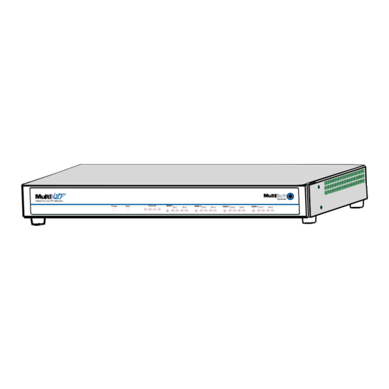
Page 14: Isdn Bri Multivoip Front Panel Leds
VOIP data channel. Active LEDs. On the MVP810ST, there are four sets of ISDN-operation LEDs. On the MVP410ST, there are two sets of ISDN-operation LEDs. Each set contains one “D” LED and two sets of channel operation LEDs (XMT and RCV). -
Page 15: Isdn-Bri Multivoip Led Descriptions
ISDN-BRI MultiVOIP LED Descriptions MVP-410ST/810ST Front Panel LED Definitions DESCRIPTION LED NAME General Operation LEDs (one set on each MultiVOIP model) Power Indicates presence of power. Boot After power up, the Boot LED will be on briefly while the MultiVOIP is booting. It lights whenever the MultiVOIP is booting or downloading a setup configuration data set. -
Page 16: Computer Requirements
Computer Requirements The computer on which the MultiVOIP’s Windows configuration program is installed must meet these requirements: • must be IBM-compatible PC with MS Windows operating system; • must have an available COM port for connection to the MultiVOIP. However, this PC does not need to be connected to the MultiVOIP permanently. -
Page 17: Specifications
Specifications Parameter MVP410ST ……/Model 100-240VAC Operating 1.2-0.6 A Voltage/ Current 50/60 Hz Mains Frequencies 12 watts Power Consumption 1.75” H x Mechanical 17.4” W x Dimensions 8.5” D 4.5cm H x 44.2 cm W x 21.6 cm D 6.61 lbs. -
Page 18: Installation At A Glance
Viewing and printing a user guide from the Web also requires that you have the Acrobat Reader loaded on your system. To select the MultiVOIP User Guide from the Multi-Tech Systems home page, click Documents and then click MultiVOIP Family in the product list drop-down window. All documents for this MultiVOIP Product Family will be displayed. -
Page 19: Chapter 2: Quick Start Instructions
MultiVOIP Quick Start Instructions Chapter 2: Quick Start Instructions... -
Page 20: Introduction
When the battery starts to weaken, the date and time may be incorrect. If the battery fails, the board must be sent back to Multi-Tech Systems for battery replacement. Warning: There is danger of explosion if the battery is incorrectly replaced. -
Page 21: Multivoip Startup Tasks
MultiVOIP Startup Tasks Task Collecting Phone/IP Details ( vital! ) Placement Command/Control Computer Setup: Specs & Settings Hookup Software Installation Phone/IP Starter Configuration Phonebook Starter Configuration Connectivity Test Troubleshooting Summary The MultiVOIP must be configured to interface with your particular phone system and IP network. -
Page 22: Phone/Ip Details *Absolutely Needed* Before Starting The Installation
BRI ports will be terminal side. • If you are connecting the MultiVOIP to network equipment with a “U” interface, an NT1 device must be connected between them. Info needed to operate: all MultiVOIP models. Needed for: MVP810ST MVP410ST... -
Page 23: Obtain Email Address For Voip (For Email Call Log Reporting)
MultiVOIP Quick Start Instructions Gathering Phone/IP Details Phone/IP Details Often Needed/Wanted Obtain Email Address for VOIP (for email call log reporting) required if log reports of VOIP call traffic Optional are to be sent by email SMTP Parameters Preparation Task: Ask Mail Server To: I.T. -
Page 24: Config Info Checklist
Config Info CheckList Type of Config Info Gathered IP info for voip unit ● IP address ● Gateway ● DNS IP (if used) ● 802.1p Prioritization (if used) ISDN Layer 1 Interface (Choices: Network, Terminal) Clock Master Status (only a channel designated as Terminal can be used as the Clock Master) Switch Info... -
Page 25: Identify Remote Voip Site To Call
VOIP system, it is highly desirable to use the same VOIP protocol for all VOIP units in the system. SPP is a non-standard protocol developed by Multi-Tech. SPP is not compatible with the “Proprietary” protocol used in Multi-Tech’s earlier generation of voip gateways. -
Page 26: Placement
Placement Mount your MultiVOIP in a safe and convenient location where cables for your network and phone system are accessible. Rack-mounting instructions are in Chapter 3: Mechanical Installation & Cabling of the User Guide. Command/Control Computer Setup (Specs & Settings) The computer used for command and control of the MultiVOIP (a) must be an IBM-compatible PC, (b) must use a Microsoft operating system,... - Page 27 MultiVOIP Quick Start Instructions Quick Hookups Hookup for MVP410ST & MVP810ST...
-
Page 28: Load Multivoip Control Software Onto Pc
Load MultiVOIP Control Software onto PC For more details, see Chapter 4: Software Installation in this manual. 1. MultiVOIP must be properly cabled. Power must be turned on. 2. Insert MultiVOIP CD into drive. Allow 10-20 seconds for Autorun to start. -
Page 29: Phone/Ip Starter Configuration
Phone/IP Starter Configuration For full details, see the Technical Configuration chapter of this manual. 1. Open MultiVOIP program: Start | MultiVOIP xxx | Configuration. 2. Go to Configuration | Ethernet/IP. Enter the IP parameters for your voip site. Activate Packet Prioritization (802.1p) if desired. If you use a Domain Name Server (DNS), specify its IP address. - Page 30 4. Web Browser GUI Setup (Optional). To do configuration and operation procedures using the web browser GUI, you must first set it up. To do so, follow these steps. (The browser used must be Internet Explorer 6.0 or above; or Netscape 6.0 or above; or FireFox 1.0 or above.) A.
- Page 31 Phone/IP Starter Configuration (continued) 5. Go to Configuration | Voice/Fax. Select Coder | “Automatic.” At the right-hand side of the dialog box, click OK. If you know any specific parameter values that will apply to your system, enter them. Click Copy Channel. Select Copy to All. Click Copy. At main Voice/Fax Parameters screen, click OK to exit from the dialog box.
- Page 32 Typically the email log reports are sent to the Voip Administrator but they can be sent to any email address. Decide where you want the email logs sent and enter that email address in the “Recipient Address” field. Whenever email log messages are sent out, they must have a standard Subject line.
- Page 33 Phone/IP Starter Configuration (continued) 12. Enable premium (H.450) telephony features. Go to Supplementary Services. Select any features to be used. For Call Hold, Call Transfer, & Call Waiting, specify the key sequence that the phone user will press to invoke the feature. For Call Name Identification, specify the allowed name types to be used and a caller- id descriptor.
-
Page 34: Phonebook Starter Configuration (With Remote Voip)
Phonebook Starter Configuration (with remote voip) If the topic of voip phone books is new to you, it may be helpful to read the PhoneBook Tips section (page 41) before starting this procedure. To do this part of the quick setup, you need to know of another voip that you can call to conduct a test. - Page 35 4. Suppose you want to call a phone number outside of your building using a phone station that is an extension from your PBX system (if present). What digits must you dial? Often a “9” or “8” must be dialed to “get an outside line” through the PBX (i.e., to connect to the PSTN).
- Page 36 5. In the “Destination Pattern” field of the Add/Edit Outbound Phonebook screen, enter the digits from step 4 followed by the digits from step 3. North America, Long-Distance Example Seattle-Chicago system. : enter 81312 as Answer Destination Pat- tern in Outbound Phone-book of Seattle voip.
- Page 37 6. In the “Remove Prefix” field, enter the initial PBX access digit (“8” or “9”). North America, Long-Distance Example Seattle-Chicago system. : enter 8 in “Remove Answer Prefix” field of Seattle Outbound Phonebook. Euro, International Call Example Rotterdam/Bordeaux system. : enter 9 in “Remove Prefix” field of Outbound Answer Phonebook for Rotterdam voip.
-
Page 38: Inbound Phonebook
Inbound Phonebook 1. Open the MultiVOIP program. ( Start | MultiVOIP xxx | Configuration ) 2. Go to Phone Book | Inbound Phonebook | Add Entry. 3. In the “Remove Prefix” field, enter your local calling code (area code, country code, city code, etc.) preceded by any other “access digits” that are required to reach your local site from the remote voip location (think of it as though the call were being made through the PSTN –... - Page 39 4. In the “Add Prefix” field, enter any digits that must be dialed from your local voip to gain access to the PSTN. North America, Long-Distance Example Seattle-Chicago system. On Seattle PBX, “9” is used to get an outside line. Answer: 9 is prefix to be added by local (Seattle) voip.
- Page 40 6. In the “Description” field, it is useful to describe the ultimate destination of the calls. For example, in a New York City voip system, “incoming calls to Manhattan office,” might describe a phonebook entry, as might the descriptor “incoming calls to NYC local calling area.”...
-
Page 41: Phonebook Tips
Phonebook Tips Preparing the phonebook for your voip system is a complex task that, at first, seems quite daunting. These tips may make the task easier. Use Dialing Patterns, Not Complete Phone Numbers generally enter complete phone numbers in the voip phonebook. Instead, you’ll enter “destination patterns”... - Page 42 . There are digits (PSTN access codes) that must be access codes dialed to gain access to an operator, to access the publicly switched ‘long-distance’ calling system(North America), to access the publicly switched ‘national’ calling system (Europe and elsewhere), or to access the publicly switched ‘international’...
- Page 43 Using a Comma Commas are used in telephone dialing strings to indicate a pause to allow a dial tone to appear (common on PBX and key systems). Commas may be used only in the “Add Prefix” field of the Inbound Phonebook. .
- Page 44 Phonebook Tips MultiVOIP Quick Start Instructions NOTES...
-
Page 45: Phonebook Example
Phonebook Example Boise Office Area: 208 PBX System. Main Number: 333-2700 PSTN 90 extensions 204.16.49.73 24-Channel Digital VoIP (MVP2410) Inbound Phonebook Each contains Inbound Phonebook tw o entries. The first entry (4 digits) specifies how incoming calls from the other voip sites w ill be handled if they go out onto the local PSTN . - Page 46 Voip Sites with Phonebooks Boise Office Boise Voip Inbound Phonebook Area: 208 Prefix to Prefix PBX System. to Add Remove Main Number: 91208 333-2700 PSTN 90 extensions 204.16.49.73 24-Channel Digital VoIP (MVP2410) Network Santa Fe Voip Santa Fe Voip Inbound Phonebook Outbound Phonebook Prefix to Prefix...
- Page 47 Sample Phonebooks Enlarged Boise Voip Inbound Phonebook Outbound Phonebook Prefix to Prefix Description Destin. Total to Add Incoming Calls Digits Remove Pattern 91208 Incoming calls 91505 to PSTN, Boise Area i ncoming calls to extensions of company’s PBX system in Boise 91520 Santa Fe Voip Inbound Phonebook...
- Page 48 Phonebook Worksheet Voip Location/ID:____________________________ Inbound Phonebook Outbound Phonebook Prefix Description Total Prefix to Destin. to Add Incoming Calls Digits Remove Pattern Other Details: Voip Location/ID:____________________________ Inbound Phonebook Prefix to Prefix Description Destin. to Add Incoming Calls Remove Pattern Other Details: Voip Location/ID:____________________________ Inbound Phonebook Outbound Phonebook...
- Page 49 MultiVOIP Quick Start Instructions Phonebook Example Enlarged Phonebook Worksheet...
-
Page 50: Connectivity Test
Connectivity Test The procedures “Phone/IP Starter Configuration” and “Phonebook Starter Configuration” must be completed before you can do this procedure. 1. These connections must be made: MultiVOIP to local PBX MultiVOIP to command PC MultiVOIP to Internet 2. Inbound Phonebook and Outbound Phonebook must both be set up with at least one entry in each. - Page 51 4. You now need to free up the COM port connection (currently being used by the MultiVOIP program) so that the HyperTerminal program can use it. To do this, you can either (a) click on Connection in the sidebar and select “Disconnect” from the drop-down box, or (b) close down the MultiVOIP program altogether.
- Page 52 7. Make VOIP call. for ISDN-BRI MultiVOIPs (MVP-410ST/810ST) in terminal mode; Make call from an extension of the local PBX to the voip extension. 8. Read console messages recorded on HyperTerminal. Console Messages from Originating VOIP. The voip unit that originates the call will send back messages like that shown below.
- Page 53 Console Messages from Terminating VOIP. The voip unit connected to the phone where the call is answered will send back messages like that shown below. [00170860] H323[0]: New incoming call [00170860] PSTNIF : Placing call on channel 0 Outbound digit 7175662 [00170885] CAS[0] : TX : ABCD = 1, 1, 1, 1 [00171095] H323IF [0]: MasterSlaveStatus=Master [00171105] CAS[0] : RX : ABCD = 1, 1, 1, 1,Pstn State[7]...
-
Page 54: Troubleshooting
Troubleshooting If you cannot establish connectivity between two voips in the system, follow the steps below to determine the problem. 1. Ping both MultiVOIP units to confirm connectivity to the network. 2. Verify the telephone connections. Check cabling. Are connections well seated? To correct receptacle? If terminal equipment is connected to the voip, then "Network"... -
Page 55: Chapter 3: Mechanical Installation And Cabling
Chapter 3: Mechanical Installation and Cabling... -
Page 56: Introduction
When the battery starts to weaken, the date and time may be incorrect. If the battery fails, the board must be sent back to Multi-Tech Systems for battery replacement. Warning: There is danger of explosion if the battery is incorrectly replaced. -
Page 57: Unpacking Your Mvp-410St/810St Multivoip
Unpacking Your MVP-410ST/810ST MultiVOIP When unpacking your MultiVOIP, check to see that all of the items shown in Figure 3-1 are included in the box. If any box contents are missing, contact MultiTech Tech Support at 1-800-972-2439. MultiVOIP Cabling Guide Power Boot Figure 3-1: Unpacking the MVP-410ST/810ST... -
Page 58: Rack Mounting Instructions For Mvp410St & Mvp810St
Rack Mounting Instructions for MVP410ST & MVP810ST The MultiVOIPs can be mounted in an industry-standard EIA 19-inch rack enclosure, as shown in Figure 3-2. Figure 3-2: Rack-Mounting (MVP410ST or MVP810ST) -
Page 59: Safety Recommendations For Rack Installations
MultiVOIP User Guide Mechanical Installation & Cabling Safety Recommendations for Rack Installations Ensure proper installation of the unit in a closed or multi-unit enclosure by following the recommended installation as defined by the enclosure manufacturer. Do not place the unit directly on top of other equipment or place other equipment directly on top of the unit. -
Page 60: 19-Inch Rack Enclosure Mounting Procedure
5. Remove feet (4) from the MultiVOIP unit. 6. Mount the MultiVOIP in the rack enclosure per the rack manufacture’s mounting procedure. Figure 3-3: Bracket Attachment for Rack Mounting (MVP410ST & MVP810ST) Figure 3-4: Attaching MultiVOIP to Rack Rail (MVP410ST & MVP810ST) -
Page 61: Cabling Procedure For Mvp-410St/810St
Cabling Procedure for MVP-410ST/810ST Cabling involves connecting the MultiVOIP to your LAN and telephone equipment. 1. Connect the power cord supplied with your MultiVOIP to a live AC outlet and to the power connector on the back of the MultiVOIP as shown at top right in Figure 3-5. - Page 62 . When a voip ISDN connector is to be connected to a Terminal Mode PBX extension line or to a telco line, select “Terminal” as the “Layer 1 Interface” in the ISDN Parameters screen. When making cable connections, an NT1 device will be needed between the MultiVOIP and the PSTN or between the MultiVOIP and any PBX with a “U”...
- Page 63 . When a voip ISDN connector is to be connected to an Network Mode ISDN phone station or to an ISDN terminal adapter (TA), select “Network” as the “Layer 1 Interface” in the ISDN Parameters screen of the MultiVOIP software. Connect cables between voip ISDN connectors and phone or TA.
- Page 64 5. Repeat the above step to connect the remaining ISDN telephone equipment to each ISDN connector on your MultiVOIP. Be aware that you can assign each ISDN line separately and independently to either Network mode or Terminal mode. That is, all ISDN lines do not have to be assigned in to the same operating mode.
- Page 65 connection to be considered permanent, the grounding wire must connect to the earth ground of the building's electrical wiring system and the ground connection must use a screw terminal or other reliable means of fastening. The ground connection must not be as easily disconnected as, for example, a power cord.
-
Page 66: Chapter 4: Software Installation
Chapter 4: Software Installation... -
Page 67: Introduction
Introduction Configuring software for your MultiVOIP entails three tasks: (1) loading the software onto the PC (this is “Software Installation and is discussed in this chapter), (2) setting values for telephony and IP parameters that will fit your system (this is “Technical Configuration” and it is discussed in Chapter 5), and (3) establishing “phonebooks”... - Page 68 2. Insert the MultiVOIP CD into your CD-ROM drive. The CD should start automatically. It may take 10 to 20 seconds for the Multi-Tech CD installation window to display. If the Multi-Tech Installation CD window does not display automatically, click My Computer, then right click the CD ROM drive icon, click Open, and then click the Autorun icon.
- Page 69 4. A ‘welcome’ screen appears. Press Enter or click Next to continue. 5. Follow the on-screen instructions to install your MultiVOIP software. The first screen asks you to choose the folder location of the files of the MultiVOIP software. Choose a location and click Next.
- Page 70 Software Installation MultiVOIP User Guide 6. At the next screen, you must select a program folder location for the MultiVOIP software program icon. Click Next. Transient progress screens will appear while files are being copied.
- Page 71 7. A completion screen will appear. Click Finish. 8. When setup of the MultiVOIP software is complete, you will be prompted to run the MultiVOIP software to configure the VOIP. Software installation is complete at this point. You may proceed with Technical Configuration now, or not, at your convenience.
-
Page 72: Un-Installing The Multivoip Configuration Software
Un-Installing the MultiVOIP Configuration Software 1. To un-install the MultiVOIP configuration software, go to Start | Programs and locate the entry for the MultiVOIP program. Select Uninstall. 2. Two confirmation screens will appear. Click Yes and OK when you are certain you want to continue with the uninstallation process. - Page 73 MultiVOIP User Guide Software Installation 3. A special warning message similar to that shown below may appear concerning the MultiVOIP software’s “.bin” file. Click Yes. 4. A completion screen will appear. Click Finish.
-
Page 74: Chapter 5: Technical Configuration
Chapter 5: Technical Configuration... -
Page 75: Configuring The Multivoip
MultiVOIP User Guide Technical Configuration Configuring the MultiVOIP There are two ways in which the MultiVOIP must be configured before operation: technical configuration and phonebook configuration. Technical Configuration. First, the MultiVOIP must be configured to operate with technical parameter settings that will match the equipment with which it interfaces. - Page 76 Technical Configuration MultiVOIP User Guide 192.168.3.143 is the default IP address set at the factory for all MultiVOIP units. Once you have established contact, you will need to set up a different IP address that better fits your system.) Changes to this initial configuration can be done either locally or remotely.
- Page 77 Functional Equivalence of Interfaces. The MultiVOIP Windows configuration program is generally used to do the initial configuration (that is, setting an IP address for the MultiVOIP unit) so that the VOIP unit can communicate with the the web browser GUI. Management of the VOIP after that point can be done from either of these two programs since they both offer essentially the same functionality.
-
Page 78: Local Configuration
Local Configuration This manual primarily describes local configuration with the Windows GUI. After IP addresses have been set locally using the Windows GUI, most aspects of configuration (logging functions are an exception) can be handled through the web browser GUI, as well (see the Operation and Maintenance chapter of this manual). -
Page 79: Ip Parameters
IP Parameters The following parameters must be known about the network (LAN, WAN, Internet, etc.) to which the MultiVOIP will connect: Ask your computer network administrator. IP Network Parameters: Record for each VOIP Site in System • IP Address • IP Mask •... -
Page 80: Smtp Parameters (For Email Call Log Reporting)
Technical Configuration MultiVOIP User Guide SMTP Parameters (for email call log reporting) required if log reports of VOIP call traffic Optional are to be sent by email SMTP Parameters Preparation Task: Ask Mail Server To: I.T. Department re: email account for VOIP administrator to set up email account (with password) for the... -
Page 81: Config Info Checklist
Config Info CheckList Type of Config Info Gathered IP info for voip unit ● IP address ● Gateway ● DNS IP (if used) ● 802.1p Prioritization (if used) ISDN Layer 1 Interface (Choices: Network, Terminal) Clock Master Status (only a channel designated as Terminal can be used as the Clock Master) -
Page 82: Local Configuration Procedure (Summary)
Local Configuration Procedure (Summary) After the MultiVOIP configuration software has been installed in the ‘Command’ PC (which is connected to the MultiVOIP unit), several steps must be taken to configure the MultiVOIP to function in its specific setting. Although the summary below includes all of these steps, some are optional. -
Page 83: Local Configuration Procedure (Detailed)
18. Set Supplementary Services Parameters. The Supplementary Services screen allows voip deployment of features that are normally found in PBX or PSTN systems (e.g., call transfer and call waiting). 19. View System Info screen and set the updating interval (optional). 20. - Page 84 Technical Configuration MultiVOIP User Guide 3. Confirm Connection. If the MultiVOIP is set for an available COM port and is correctly cabled to the PC, the MultiVOIP main screen will appear. (If the main screen appears grayed out and seems inaccessible, go to step 4.) In the lower left corner of the screen, the connection status of the MultiVOIP will be displayed.
- Page 85 4. Solving Common Connection Problems. A. Fixing a COM Port Problem. If the MultiVOIP main screen appears but is grayed out and seems inaccessible, the COM port that was specified for its communication with the PC is unavailable and must be changed.
- Page 86 4B. Fixing a Cabling Problem. If the MultiVOIP cannot be located by the computer, two error messages will appear (saying “Multi-VOIP Not Found” and “Phone Database Not Read”). In this case, the MultiVOIP is simply disconnected from the network. For instructions on MultiVOIP cable connections, see the Cabling section of Chapter 3.
- Page 87 MultiVOIP User Guide Technical Configuration 6. Set Ethernet/IP Parameters. This dialog box can be reached by pulldown menu, toolbar icon, keyboard shortcut, or sidebar. Accessing “Ethernet/IP Parameters” Pulldown Icon Shortcut Sidebar Ctrl + Alt + I...
- Page 88 Technical Configuration MultiVOIP User Guide In each field, enter the values that fit your particular network.
- Page 89 The Ethernet/IP Parameters fields are described in the tables and text passages below. Note that both DiffServ parameters (Call Control PHB and VoIP Media PHB) must be set to zero if you enable Packet Prioritization (802.1p). Nonzero DiffServ values negate the prioritization scheme.
- Page 90 Ethernet/IP Parameter Definitions (cont’d) Field Name Values Ethernet Parameters 802.1p 4 – Controlled Load : applications subject to some form of (continued) “Admission Control”, such as preplanning of Network requirement, characterized by bandwidth reservation per flow. Traffic characterized by 5 – Video : delay <...
- Page 91 Ethernet/IP Parameter Definitions (cont’d) Field Name Values IP Parameter fields Gateway alphanumeric Name Enable DHCP disabled by default IP Address 4-places, 0-255 IP Mask 4-places, 0-255 Gateway 4-places, 0-255. Description Descriptor of current voip unit to distinguish it from other units in system. Dynamic Host Configuration Protocol is a method for assigning IP...
- Page 92 Ethernet/IP Parameter Definitions (cont’d) Field Name Values DiffServ PHB (Per Hop Behavior) values DiffServ pertain to a differential prioritizing Parameter system for IP packets as handled by fields DiffServ-compatible routers. values, each with an elaborate technical description. These descriptions are found in TCP/IP standards RFC2474, RFC2597, and, for present purposes, in RFC3246, which describes the value 34 (34 decimal;...
- Page 93 The IP Datagram with Header, Its Type-of-Service field, & DiffServ bits => VERS HLEN TYPE OF SERVICE IDENTIFICATION TIME TO LIVE PROTOCOL SOURCE IP ADDRESS DESTINATION IP ADDRESS IP OPTIONS (if any) The TOS field consists of eight bits, of which only the first six are used. These six bits are called the “Differentiated Service Codepoint”...
- Page 94 Ethernet/IP Parameter Definitions (cont’d) Field Name Values FTP Parameter fields FTP Server Enable Default = disabled See “FTP Server File Transfers” in Operation & Maintenance chapter. DNS Parameter fields Enable DNS Default = disabled Enable SRV DNS Server IP 4-places, 0-255. Address Description MultiVOIP unit has an...
- Page 95 About Service Records An SRV record holds the following information: • Service: the symbolic name of the desired service. • Protocol: this is usually either TCP or UDP. • Domain name: the domain for which this record is valid. • TTL: standard DNS time to live field.
- Page 96 7. Set up the Web Browser GUI (Optional). After an IP address for the MultiVOIP unit has been established, you can choose to do any further configuration of the unit (a) by using the MultiVOIP web browser GUI, or (b) by continuing to use the MultiVOIP Windows GUI. If you want to do configuration work using the web browser GUI, you must first set it up.
- Page 97 8. Set Voice/FAX Parameters. This dialog box can be reached by pulldown menu, toolbar icon, keyboard shortcut, or sidebar. Accessing “Voice/FAX Parameters” Pulldown Shortcut Ctrl + H Icon Sidebar...
- Page 98 Technical Configuration MultiVOIP User Guide In each field, enter the values that fit your particular network.
- Page 99 MultiVOIP User Guide Technical Configuration Note that Voice/FAX parameters are applied on a channel-by-channel basis. However, once you have established a set of Voice/FAX parameters for a particular channel, you can apply this entire set of Voice/FAX parameters to another channel by using the Copy Channel button and its dialog box.
- Page 100 The Voice/FAX Parameters fields are described in the tables below. Voice/Fax Parameter Definitions Field Name Values Description Default When this button is clicked, all Voice/FAX parameters are set to their default values. Select Channel to be configured is selected 1-4 (410ST) Channel here.
- Page 101 Voice/Fax Parameter Definitions (cont’d) Field Name Values Description DTMF Parameters Duration 60 – 3000 When DTMF: Out of Band is selected, (DTMF) this setting determines how long each DTMF digit ‘sounds’ or is held. Default = 100 ms. Not supported in 5.02c BRI software.
- Page 102 -18.5 dB Controls output level of fax tones. To Default = to –3.5 dB be changed only under the direction of -9.5 dB Multi-Tech’s Technical Support. Jitter Value Default = Defines the inter-arrival packet (Fax) 400 ms deviation (in milliseconds) for the fax transmission.
- Page 103 Voice/Fax Parameter Definitions (cont’d) Coder Parameters Coder Manual or Determines whether selection of Auto- coder is manual or automatic. matic When Automatic is selected, the local and remote voice channels will negotiate the voice coder to be used by selecting the highest bandwidth coder supported by both sides without exceeding the Max Bandwidth setting.
- Page 104 Voice/Fax Parameter Definitions (cont’d) Field Name Values Description Advanced Features Silence Determines whether silence Compression compression is enabled (checked) for this voice channel. With Silence Compression enabled, the MultiVOIP will not transmit voice packets when silence is detected, thereby reducing the amount of network bandwidth that is being used by the voice channel.
- Page 105 Voice/Fax Parameter Definitions (cont’d) Field Name Values Description AutoCall/Offhook Alert Parameters Auto Call / AutoCall, The AutoCall option enables the local Offhook Offhook MultiVOIP to call a remote MultiVOIP Alert Alert without the user having to dial a Phone Directory Database number. As soon as you access the local MultiVOIP voice/fax channel, the MultiVOIP immediately connects to the remote...
- Page 106 Voice/Fax Parameter Definitions (cont’d) Field Name Values Description AutoCall/Offhook Alert Parameters Auto Call / AutoCall, (continued from previous page) Offhook Offhook Both functions apply on a channel-by- Alert Alert channel basis. It would not be appropriate for either of these functions to be applied to a channel that serves in a pool of available channels for general phone traffic.
- Page 107 Voice/Fax Parameter Definitions (cont’d) ) Field Name Values Description Dynamic Jitter Dynamic Dynamic Jitter defines a minimum Jitter Buffer and a maximum jitter value for voice communications. When receiving voice packets from a remote between packets may occur due to network traffic problems.
-
Page 108: Modem Relay
Voice/Fax Parameter Definitions (cont’d) Field Name Values Dynamic Jitter Maximum 60 to 400 Jitter Value Optimizat- 0 to 12 ion Factor Modem Relay To place modem traffic onto the voip network (an application called “modem relay”), use Coder G.711 mu-law at 64kbps. Description The maximum dynamic jitter buffer of 400 milliseconds is the maximum... - Page 109 Voice/Fax Parameter Definitions (cont’d) Field Name Values Description CID Manipulation Disable checked Caller ID is disabled when checked and enabled when not checked. unchecked When CID is disabled, the CID from the BRI line is blocked. Mode Transparent, Transparent: no changes are made to User, the caller-ID received from the BRI line.
- Page 110 Voice/Fax Parameter Definitions (cont’d) ) Field Name Values Description Auto Disconnect Automatic The Automatic Disconnection Disconnect- group provides four options which can be used singly or in any combination. Jitter Value 1-65535 The Jitter Value defines the average milli- inter-arrival packet deviation (in seconds milliseconds) before the call is automatically disconnected.
- Page 111 9. Set Call Signaling Parameters. This dialog box leads to 3 others, one for each of the call-signaling types supported (H.323, SIP, and SPP). These dialog boxes can be reached by pulldown menu, keyboard shortcut, or a sidebar menu. Accessing “Call Signaling Parameters” Pulldown Shortcut Alt + C...
- Page 112 The tables below describes all fields in the general H.323 Call Signaling screen. H.323 Call Signaling Parameter Definitions Field Name Values Description Use Fast Start Enables the H.323 Fast Start procedure. May need to be enabled/disabled for compatibility with third-party VOIP gateways.
- Page 113 H.323 Call Signaling Parameter Defns (cont’d) Field Name Values Description GateKeeper RAS Parameters Primary GK This is the preferred gatekeeper for controlling the traffic of the (Gatekeeper) current voip. Alternate GK A first and a second alternate gatekeeper can be specified for (Gatekeepers) use by the current voip for 1 and 2...
- Page 114 H.323 Call Signaling Parameter Defns (cont’d) GateKeeper RAS Parameters Field Name Values RAS TTL in seconds Value Gatekeeper integer Discovery 60 - 300 Polling Interval Use Online When selected, voip will seek an alternate Alternate gatekeeper (when none of the 3 gatekeepers Gatekeeper shown on this screen are available) from a List...
- Page 115 H.323 Call Signaling Parameter Definitions (cont’d) Field Name Values Description H.323 Version 4 Parameters H.323 Signaling for multiple phone Multiplexing calls can be carried on a single (Mux) port rather than opening a separate signaling port for each call. This conserves bandwidth resources.
- Page 116 H.323 Call Signaling Parameter Definitions (cont’d) Field Name Values Description H.323 Version 4 Parameters Parallel H.245 Values : Y/N (FS + Tun) Description : FS (Fast Start or Fast Connect) is a Q.931 feature of H.323v2 to hasten call setup as well as ‘pre-opening’ the media channel before the CONNECT message is sent.
- Page 117 The tables below describes all fields in the general SIP Call Signaling screen. SIP Call Signaling Parameter Definitions Field Name Values SIP Proxy Parameters Signaling Port Use SIP Proxy Description Port number on which the MultiVOIP UserAgent software module will be waiting for any incoming SIP requests.
- Page 118 SIP Call Signaling Parameter Definitions (cont’d) Field Name Values Description SIP Proxy Parameters Allow When selected, incoming calls Incoming Calls are accepted only if those calls Through SIP come through the gatekeeper. Proxy Only Primary Proxy This is the preferred SIP proxy server for controlling the traffic of the current voip.
- Page 119 SIP Call Signaling Parameter Definitions (cont’d) Field Name Values & Description SIP Proxy Parameters Password Values : alphanumeric Description : Password for proxy server function. See “User Name” description above. Values : numeric (in seconds) Registration Description : This is the timeout interval for Time registration of the MultiVOIP with a SIP proxy server.
- Page 120 Technical Configuration MultiVOIP User Guide...
- Page 121 The tables below describes all fields in the general SPP Call Signaling screen. SPP Call Signaling Parameter Definitions (cont’d) Field Name Values Single Port Protocol (SPP) Mode Direct, Client, or Registrar General Options Port Re-trans- mission (in ms) Re-trans- mission Description SPP voip systems can operate in two modes:...
- Page 122 SPP Call Signaling Parameter Definitions (cont’d) Field Name Values Description Single Port Protocol (SPP) [continued] Client Option fields are active Client Options only in registrar/client mode and only for client voip units. Primary This is the preferred SPP registrar gateway for controlling the traffic Registrar of the current voip.
- Page 123 SPP Call Signaling Parameter Definitions (cont’d) Field Name Values Proxy/NAT Device Parameters Behind Proxy/NAT device Proxy/NAT n.n.n.n Device where Parameters – n=0-255 Public IP Address An example of a NAT-equipped SPP network is shown below. About SPP Proxy/NAT Device Parameters SPP Client/Registrar System Private IP Registrar...
- Page 124 Technical Configuration MultiVOIP User Guide 10. Set ISDN Parameters. This dialog box can be reached by pulldown menu, keyboard shortcut, or sidebar. Accessing ISDN (BRI) Parameters Pulldown Icon Shortcut Sidebar Ctrl + F...
- Page 125 ISDN that you will use. Configure each BRI interface per the requirements of your voip system. The MVP410ST has two ISDN-BRI interfaces and four channels; the MVP810ST has four ISDN-BRI interfaces and eight...
- Page 126 Technical Configuration MultiVOIP User Guide Note that ISDN BRI parameters are applied on an interface-by-interface basis. However, once you have established a set of ISDN BRI parameters for a particular interface, you can apply this entire set of parameters to another interface by using the Copy Interface button and its dialog box.
- Page 127 ISDN-BRI Parameter Definitions Field Name Values Select BRI ISDNn Interface for n= 1-2 (410ST) for n=1-4 (810ST) Layer 1 Interface Terminal, Network, Clock Master Description In this field, you will choose which ISDN port you are configuring. The 410ST has two ISDN –BRI ports (or “interfaces”);...
-
Page 128: Switch Information
ISDN-BRI Parameter Definitions (continued) Field Name Values Description Dialing Inter Digit Dialing options are relevant when the MultiVOIP provides dial tone either during Options Timer an overlap receiving mode or providing a (value in second dial tone. Default is 2000, which is 2 milliseconds) seconds. - Page 129 ISDN-BRI Parameter Definitions (continued) Field Name Values Description Numbering Details Number Calling Party Support for the user to select the Calling Type: Party Number Type. Unknown, Local is valid only for AT5 operator – local International, (directory) number. National, There may be cases where the default Type Net_Spf, of Number and/or Numbering Plan may Subscriber,...
- Page 130 ISDN-BRI Parameter Definitions (continued) Field Name Values Description MSN Details Right most Multiple Subscriber Numbering (MSN) – MSN n digits to be In Euro-ISDN, and some country specific distinguished variants, it is possible to have several ISDN numbers for the same BRI or PRI connection.
- Page 131 MultiVOIP User Guide Technical Configuration Country and Operator options for the MVP-410ST/810ST voip units are listed below.
- Page 132 Technical Configuration MultiVOIP User Guide 11. Set SNMP Parameters (Remote Voip Management). SNMP and MultiVoipManager are not supported for BRI MultiVOIPs. Please skip to step 12. This dialog box can be reached by pulldown menu, keyboard shortcut, or sidebar. To make the MultiVOIP controllable by a remote PC running the MultiVoipManager software, check the “Enable SNMP Agent”...
- Page 133 MultiVOIP User Guide Technical Configuration In each field, enter the values that fit your particular system.
- Page 134 The SNMP Parameter fields are described in the table below. SNMP Parameter Definitions Field Name Values Enable SNMP Agent Trap Manager Parameters Address 4 places; n.n.n.n n = 0-255 Community Name Port Number Community Length = 19 Name 1 characters (max.) Case sensitive.
- Page 135 MultiVOIP User Guide Technical Configuration 12. Set Regional Parameters (Phone Signaling Tones & Cadences). This dialog box can be reached by pulldown menu, keyboard shortcut, or sidebar. Accessing “Regional Parameters” Pulldown Icon Shortcut Sidebar Ctrl + R...
- Page 136 Technical Configuration MultiVOIP User Guide The Regional Parameters screen will appear. For the country selected, the standard set of frequency pairs will be listed for dial tone, busy tone, ‘unobtainable’ tone (fast busy or trunk busy), ring tone, and other, more specialized tones. In each field, enter the values that fit your particular system.
- Page 137 The Regional Parameters fields are described in the table below. “Regional Parameter” Definitions Field Name Values Country/ USA, Japan, UK, Region Custom Description Name of a country or region that uses a certain set of tone pairs for dial tone, ring tone, busy tone (fast busy tone), unobtainable tone (tone heard...
- Page 138 “Regional Parameter” Definitions Field Name Values Country/ USA, Japan, UK, Region Custom Note “Survivability” tone indicates a special type of call-routing redundancy. Standard Tones fields Type column dial tone, ring tone, busy tone, unobtainable tone (fast busy), survivability tone, re-order tone Frequency 1 freq.
- Page 139 “Regional Parameter” Definitions (cont’d) Field Name Values Standard Tones fields (cont’d) Gain 1 gain in dB +3dB to –31dB and “mute” setting Gain 2 gain in dB +3dB to –31dB and “mute” setting Cadence n/n/n/n (msec) On/Off four integer time values in milli-seconds;...
- Page 140 “Regional Parameter” Definitions (cont’d) Field Name Values User Defined Tones fields Type column alphanumeric name specified by user Frequency 1 freq. in Hertz Frequency 2 freq. in Hertz Gain 1 gain in dB +3dB to –31dB and “mute” setting Gain 2 gain in dB +3dB to –31dB and “mute”...
- Page 141 MultiVOIP User Guide Technical Configuration 13. Set Custom Tones and Cadences (optional). The Regional Parameters dialog box has a secondary dialog box that allows you to customize DTMF tone pairs to create unique ring-tones, dial-tones, busy-tones or “unobtainable” tones (fast busy signal) or “re-order” tones (telling the user that she must hang up an off-hook phone) or “survivability”...
- Page 142 The Custom Tone-Pair Settings fields are described in the table below. Custom Tone-Pair Settings Definitions Field Name Values Tone Pair dial tone, busy tone, ring tone, ‘unobtainable’ tone, survivability tone, re-order tone TONE PAIR VALUES Frequency 1 frequency in Hertz Frequency 2 frequency in Hertz...
- Page 143 Custom Tone-Pair Settings Definitions Field Name Values Cadence 1 integer time value in milli-seconds; zero value for dial-tone indicates continuous tone Cadence 2 duration in milliseconds Cadence 3 duration in milliseconds Cadence 4 duration in milliseconds Description On/off pattern of tone durations used to denote phone ringing, phone busy, dial tone (“0”...
- Page 144 14. Set SMTP Parameters (Log Reports by Email). The SMTP Parameters screen is applicable when the VOIP administrator has chosen to receive log reports by email (this is done by selecting the “SMTP” checkbox in the Logs/Traces screen and selecting “Enable SMTP”...
- Page 145 The SMTP Parameters screen is shown below. “SMTP Parameters” Definitions Field Name Values Enable SMTP Requires Authentication Login Name alpha- numeric, per email domain Description In order to send log reports by email, this box must be checked. However, to enable SMTP functionality, you must also select “SMTP”...
- Page 146 “SMTP Parameters” Definitions (cont’d) Field Name Values Password alpha- numeric Mail Server IP n.n.n.n Address for n= 0 to Port Number Mail Type text or html Subject text Reply-To email address Address Recipient email address Address Mail Criteria Number of integer Records Number of...
- Page 147 The SMTP Parameters dialog box has a secondary dialog box, Custom Fields, that allows you to customize email log messages for the MultiVOIP. The MultiVOIP software logs data about many aspects of the call traffic going through the MultiVOIP. The Custom Fields screen lets you pick which aspects will be included in the email log reports.
- Page 148 “Custom Fields” Definitions (cont’d) Field Description Field Total bytes sent in Bytes Bytes Sent Received call. Packets lost in Packets Coder Lost call. The DTMF dialing Outbound Prefix Digits Matched digits received by Received this gateway from the remote gateway presuming that DTMF is set to "Out of Band."...
- Page 149 “Custom Fields” Definitions (cont’d) Field Description Field The IP address of Server Outbound Digits Sent Details the traffic control server (if any) being used (whether an H.323 gatekeeper, a SIP proxy, or an SPP registrar gateway) will be displayed here if the call is handled through that server.
- Page 150 Technical Configuration MultiVOIP User Guide...
- Page 151 15. Set RADIUS parameters. You can access the RADIUS screen by pulldown menu, sidebar menu, or keyboard shortcut. In general, RADIUS is concerned with authentication, authorization, and accounting. The MultiVOIP BRI units support only the accounting function. The accounting function is well suited for billing of voip telephony services.
- Page 152 Technical Configuration MultiVOIP User Guide The fields of the RADIUS screen are described in the table below.
- Page 153 RADIUS Screen Field Definitions Field Name Values Description Enable When checked, the MultiVOIP will Accounting access the accounting functionality of Server n.n.n.n IP address of the RADIUS server that Address 0 – 255 handles accounting (billing) for the current MultiVOIP unit. Accounting TDM time slot at which RADIUS numeric;...
- Page 154 The RADIUS Parameters dialog box has a secondary dialog box, RADIUS Attributes, that allows you to customize accounting information sent to the RADIUS server by the MultiVOIP. The MultiVOIP software logs data about many aspects of the call traffic going through the MultiVOIP. The RADIUS Attributes screen lets you pick which aspects will be included in the accounting reports sent to the RADIUS server.
- Page 155 “RADIUS Attributes” Field Definitions (cont’d) Field Description Field From Details Gateway Originating Gatew N. Number gateway IP Addr IP address where IP Addr call originated. Descript Identifier of site Descript where call originated. Options When , log Options selected will not use Silence Compression and Forward Error...
- Page 156 16. Set Log Reporting Method. You can access the Logs/Traces screen by pulldown menu, sidebar menu, or keyboard shortcut. The Logs/Traces screen lets you choose how the VoIP administrator will receive log reports about the MultiVOIP’s performance and the phone call traffic that is passing through it. Log reports can be received in one of three ways: A.
- Page 157 MultiVOIP User Guide Technical Configuration If you enable console messages, you can customize the types of messages to be included/excluded in log reports by clicking on the “Filters” button and using the Console Messages Filter Settings screen (see subsequent page). If you use the logging function, select the logging option that applies to your VoIP system design.
- Page 158 “Logs” Screen Definitions Field Name Values Description Enable Allows MultiVOIP debugging messages to be Console read via a basic terminal program like Messages HyperTerminal ™ or equivalent. Normally, this should be disabled because it uses MultiVOIP processing resources. Console messages are meant for tech support personnel.
- Page 159 MultiVOIP User Guide Technical Configuration To customize console messages by category and/or by channel, click on “Filters” and use the Console Messages Filters Settings screen.
- Page 160 17. Set NAT Traversal parameters. You can access the NAT Traversal screen by pulldown menu, sidebar menu, or keyboard shortcut. NAT (Network Address Translation) parameters are applicable only when the MultiVOIP is operating in SIP mode. The use of STUN (Simple Traversal of UDP NATs) servers to aid networks with NAT devices is described in RFC 3489.
- Page 161 Descriptions for NAT Traversal screen fields are presented in the table below. NAT Traversal Definitions (cont’d) Field Name Values Description Enable Enables STUN client functionality in (STUN) the MultiVOIP. STUN (Simple Traversal of UDP through NATs (Network Address Translation)) is a protocol that allows a server to assist client gateways behind a NAT firewall or router with their packet routing.
- Page 162 18. Set Supplementary Services Parameters. This dialog box can be reached by pulldown menu, keyboard shortcut, or sidebar. Accessing “Supplementary Services” Parameters Pulldown Shortcut Ctrl + Alt +H Supplementary Services features derive from the H.450 standard, which brings to voip telephony functionality once only available with PSTN or PBX telephony.
- Page 163 In each field, enter the values that fit your particular network. Of the features implemented under Supplementary Services, three are very closely related: Call Transfer, Call Hold, and Call Waiting. Call Name Identification is similar but not identical to the premium PSTN feature commonly known as Caller ID.
- Page 164 the channel over which the call is being originated (for example, “Calling Party - Omaha Sales Office Line 2”). If that voip channel is dedicated to a certain individual, the descriptor could say that, as well (for example “Calling Party - Harold Smith in Omaha”). When the home voip receives a call from any remote voip, the home voip sends a status message back to that caller.
- Page 165 The Supplementary Services fields are described in the tables below. Supplementary Services Parameter Definitions Field Name Values Description Select The channel to be configured is 1-4 (410ST) Channel selected here. 1-8 (810ST) Call Select to enable the Call Transfer Transfer function in the voip unit.
- Page 166 Supplementary Services Definitions (cont’d) Field Name Values Description Call Hold Select to enable Call Hold function in Enable voip unit. Call Hold allows one party to maintain an idle (non-talking) connection with another party while receiving another call (Call Waiting), while initiating another call (Call Transfer), or while performing some other call management function.
- Page 167 Supplementary Services Definitions (cont’d) Field Name Values Description Call Name Enables CNI function. Call Name Identification is not the same as Caller Identification Enable ID. When enabled on a given voip unit currently being controlled by the MultiVOIP GUI (the ‘home voip’), Call Name Identification sends an identifier and status information to the administrator of the remote voip...
- Page 168 Supplementary Services Definitions (cont’d) Field Name Values Description Calling If the ‘home’ voip unit is originating Party, the call and Calling Party is selected, Allowed then the identifier (from the Caller Id Name Type field) will be sent to the remote voip (CNI) unit being called.
- Page 169 Supplementary Services Definitions (cont’d) Field Name Values Description Alerting If the ‘home’ voip unit is receiving the Party, call and Alerting Party is selected, Allowed then the identifier (from the Caller Id Name Type field) will tell the originating remote (CNI) voip unit that the call is ringing.
- Page 170 Supplementary Services Definitions (cont’d) Field Name Values Description Busy Party, If the ‘home’ voip unit is receiving a Allowed call directed toward an already Name Type engaged channel or phone station and (CNI) Busy Party is selected, then the identifier (from the Caller Id field) will tell the originating remote voip unit that the channel or called party is busy.
- Page 171 Supplementary Services Definitions (cont’d) Field Name Values Description Connected If the ‘home’ voip unit is receiving a Party, call and Connected Party is selected, Allowed then the identifier (from the Caller Id Name Type field) will tell the originating remote (CNI) voip unit that the attempted call has been completed and the connection is...
- Page 172 Supplementary Services Definitions (cont’d) Field Name Values Description Caller ID This is the identifier of a specific channel of the ‘home’ voip unit. The Caller Id field typically describes a person, office, or location, for example, “Harry Smith,” or “Bursar’s Office,”...
- Page 173 19. View the System Information screen and set the updating interval (optional). This dialog box can be reached by pulldown menu, sidebar menu, or keyboard shortcut. Accessing “System Information” Screen Pulldown Shortcut Ctrl + Alt +Y Sidebar Icon...
- Page 174 This screen presents vital system information at a glance. Its primary use is in troubleshooting. System Information Parameter Definitions Field Name Values Description Boot Indicates the version of the code that nn.nn Version is used at the startup (booting) of the voip.
- Page 175 System Information Parameter Definitions (cont’d) Field Name Values Description Configur- Indicates version of MultiVOIP nn.nn.nn. ation Configuration software (which Version includes screens for IP Parameters, alpha- SNMP Parameters, SMTP Parameters, numeric Regional Parameters, etc. Phone Book Indicates the version of the inbound numeric Version and outbound phonebook portion of...
- Page 176 Technical Configuration MultiVOIP User Guide 20. Set Baud Rate. The Connection option in the sidebar menu has a “Settings” item that includes the baud-rate setting for the COM port of the computer running the MultiVOIP software. First, it is important to note that the default COM port established by the MultiVOIP program is COM1.
- Page 177 21. Saving the MultiVOIP Configuration. When values have been set for all of the MultiVOIP’s various operating parameters, click on Save Setup in the sidebar. 22. Creating a User Default Configuration. When a “Setup” (complete grouping of parameters) is being saved, you will be prompted about designating that setup as a “User Default”...
-
Page 178: Chapter 6: T1 Phonebook Configuration
Chapter 6: T1 Phonebook Configuration (North American Telephony Standards) -
Page 179: T1 V Ersus E1 T Elephony E Nvironments
T1 Versus E1 Telephony Environments Phonebooks for Series II analog MultiVOIP units (MVP130, MVP130FXS, MVP210, MVP410, and MVP810) and ISDN-BRI MultiVOIPs (MVP-410ST/810ST) can be operated in either a North American telephony standards environment (potentially operating with T1 digital MultiVOIPs) or in a European telephony standards environment (potentially operating with E1 digital MultiVOIPs). - Page 180 T1 Phonebook Configuration MultiVOIP User Guide The “Outbound” phonebook for a particular VoIP unit describes the dialing sequences required for a call to originate locally (typically in a PBX in a particular facility) and reach any of its possible destinations at remote VoIP sites, including non-toll calls completed in the PSTN at the remote site.
- Page 181 Phonebook configuration screens can be accessed using icons or the sidebar menu. Phonebook Icons Description Phonebook Configuration Inbound Phonebook Entries List Add Inbound Phonebook Entry Edit selected Inbound Phonebook Entry Outbound Phonebook Entries List Add Outbound Phonebook Entry Edit selected Outbound Phonebook Entry...
- Page 182 Phonebook Pulldown Menu Inbound Phonebook Shortcut Alt + I Phonebook Sidebar Menu Outbound Phonebook Shortcut Alt + O...
- Page 183 MultiVOIP User Guide T1 PhoneBook Configuration 1. Select Outbound Phone Book/List Entries. Fields in the “Details” section will differ depending on the protocol (H.323, SIP, or SPP) of the selected list entry to which the details pertain. Click Add.
- Page 184 T1 Phonebook Configuration MultiVOIP User Guide 2. The Add/Edit Outbound PhoneBook screen appears. Enter Outbound PhoneBook data for your MultiVOIP unit. Note that the Advanced button gives access to the Alternate IP Routing feature, if needed. Alternate IP Routing can be implemented in a secondary screen (as described after the primary screen field definitions below).
- Page 185 The fields of the Add/Edit Outbound Phone Book screen are described in the table below. Add/Edit Outbound Phone Book: Field Definitions Field Name Values Description Accept Any When checked, “Any Number Number” appears as the value in the Destination Pattern field. The Accept Any Number feature works differently depending on whether or not...
- Page 186 Describes the facility or numeric geographical location at which the call will be completed. Protocol Type SIP or H.323 Indicates protocol to be used in outbound transmission. Single or SPP Port Protocol (SPP) is a non- standard protocol designed by Multi-Tech.
- Page 187 Add/Edit Outbound Phone Book: Field Definitions (cont’d) Field Name Values Description H.323 fields Use Gatekeepr Indicates whether or not gatekeeper is used. Gateway alpha- The H.323 ID assigned to the destination MultiVOIP. Only H.323 ID numeric valid if “Use Gatekeeper” is enabled for this entry.
- Page 188 Add/Edit Outbound Phone Book: Field Definitions (cont’d) Field Name Values Description SIP Fields Use Proxy Select if proxy server is used. Transport TCP or Voip administrator must choose Protocol between UDP and TCP transmission protocols. UDP is a high-speed, low-overhead connectionless protocol where data is transmitted without acknowledgment, guaranteed...
- Page 189 Add/Edit Outbound Phone Book: Field Def’ns Field Name Values Description SPP Fields Use Registrar Values: Description: Select this checkbox to use registrar when voip system is operating in the “Registrar/Client” SPP mode. In this mode, one voip (the registrar, as set in Phonebook Configuration screen) has a static IP address and all other voips (clients) point to the registar’s IP address as functionally their own.
- Page 190 T1 Phonebook Configuration MultiVOIP User Guide Clicking on the Advanced button brings up the Alternate Routing secondary screen. This feature provides an alternate path for calls if the primary IP network cannot carry the traffic. Often in cases of failure, call traffic is temporarily diverted into the PSTN. However, this feature could also be used to divert traffic to a redundant (backup) unit in case one voip unit fails.
- Page 191 Alternate Routing Field Definitions Field Values Description Name Alternate n.n.n.n Alternate destination for outbound data traffic where in case of excessive delay in data transmission. Address n= 0-255 Round milliseconds The Round Trip Delay is the criterion for Trip judging when a data pathway is considered Delay blocked.
- Page 192 T1 Phonebook Configuration MultiVOIP User Guide Inbound PhoneBook | List Entries 3. Select...
- Page 193 MultiVOIP User Guide T1 PhoneBook Configuration 4. The Add/Edit Inbound PhoneBook screen appears.
- Page 194 Enter Inbound PhoneBook data for your MultiVOIP. The fields of the Add/Edit Inbound PhoneBook screen are described in the table below. Add/Edit Inbound Phone Book: Field Definitions Field Name Values Description Accept Any : Y/N Values Number When checked, “Any Number” Description: appears as the value in the Remove Prefix field.
- Page 195 Add/Edit Inbound Phone Book: Field Definitions (cont’d) Field Name Values Description Call Forward Parameters Forward Uncondit.; Unconditional all calls received will be Condition Busy forwarded. No Resp. Busy will be forwarded when station is busy. No Response calls will be forwarded if called party does not answer after a specified number of rings, as specified in Ring...
- Page 196 Add/Edit Inbound Phone Book: Field Definitions (cont’d) Field Name Values and Description Ring Count When “No Response” is 0, 1, 2, 3, etc. condition for forwarding calls, this determines how many unanswered rings are needed to trigger the forwarding. Registration In an H.323 voip system, gateways can Option register with the system using one of these...
-
Page 197: T1 Phonebook Examples
T1 Phonebook Examples The following example demonstrates how Outbound and Inbound PhoneBook entries work in a situation of multiple area codes. Consider a company with offices in Minneapolis and Baltimore. 3 Sites, All-T1 Example Notice first the area code situation in those two cities: Minneapolis’s local calling area consists of multiple adjacent area codes;... - Page 198 An outline of the equipment setup in both offices is shown below. Local-Call Area Codes: 612, 651, Company HQ. Minneapolis North Sub. area 763 Digital VoIP -5174 200.2.10.3 -5173 -5172 -5171 717-5170 Network Overlay Area Code: Baltimore Sales Ofc. area 410 Digital VoIP -7003...
- Page 199 MultiVOIP User Guide T1 PhoneBook Configuration The screen below shows Outbound PhoneBook entries for the VOIP located in the company’s Baltimore facility. The entries in the Minneapolis VOIP’s Inbound PhoneBook match the Outbound PhoneBook entries of the Baltimore VOIP, as shown below.
- Page 200 T1 Phonebook Configuration MultiVOIP User Guide To call the Minneapolis/St. Paul area, a Baltimore employee must dial eleven digits. (In this case, we are assuming that the Baltimore PBX does not require an “8” or “9” to seize an outside phone line.) If a Baltimore employee dials any phone number in the 612 area code, the call will automatically be handled by the company’s voip system.
- Page 201 MultiVOIP User Guide T1 PhoneBook Configuration Similarly, the Inbound PhoneBook for the Baltimore VOIP (shown first below) generally matches the Outbound PhoneBook of the Minneapolis VOIP (shown second below). Notice the extended prefix to be removed: 14103257. This entry allows Minneapolis users to contact Baltimore co-workers as though they were in the Minneapolis facility, using numbers in the range 7000 to 7999.
- Page 202 T1 Phonebook Configuration MultiVOIP User Guide The Outbound PhoneBook for the Minneapolis VOIP is shown below. The third destination pattern, “7” facilitates reception of co-worker calls using local-appearing-extensions only. In this case, the “Add Prefix” field value for this phonebook entry would be “1410325” .
-
Page 203: Configuring Mixed Digital/Analog Voip Systems
Configuring Mixed Digital/Analog VOIP Systems Analog MultiVOIP units, like the MVP-210/410/810 are compatible with digital MultiVOIP units like the MVP2410. In many cases, digital and analog VOIP units will appear in the same telephony/IP system. In addition to MVP-210/410/810 MultiVOIP units (Series II units), legacy analog VOIP units (Series I units made by MultiTech) may be included in the system, as well. - Page 204 T1 Phonebook Configuration MultiVOIP User Guide The Series I analog VOIP phone book resides in the “Host” VOIP unit at Site B. It applies to both of the Series I analog VOIP units. Each of the Series II analog MultiVOIPs (the MVP210 and the MVP410) requires its own inbound and outbound phonebooks.
- Page 205 These seven phone books are shown below. Phone Book for Series I Analog VOIP Host Unit (Site B) VOIP Dir # IP Address Channel -OR- Destination Pattern 200.2.9.8 200.2.9.8 200.2.9.6 200.2.9.7 1615 200.2.9.9 (Note 2.) xxxx 3xxx 200.2.9.9 (Note 1.) 1402 200.2.9.5 140226374...
- Page 206 Note 1. The “x” is a wildcard character. Note 2. By specifying “Channel 0,” we instruct the MVP2400/2410 to choose any available data channel to carry the call. Note 3. Note that Site F key system has only 30 extensions (x7400-7429).
- Page 207 Outbound Phone Book for MVP2410 Digital VOIP (Site D) Destin. Remove Pattern Prefix Prefix Address 200.2.9.7 1507 1507 101# 200.2.9.8 Note 3. 200.2.9.8 200.2.9.6 1402 200.2.9.5 1402 200.2.9.5 1402 200.2.9.5 1402 200.2.9.5 Note 3. The pound sign (“#”) is a delimiter separating the VOIP number from the standard telephony phone number.
- Page 208 Inbound Phonebook for MVP2410 Digital VOIP (Site D) Remove Channel Comment Prefix Prefix Number 1615 Allows phone users at remote Note 4. voip sites to call non-toll Note 5. numbers within the Site D area code (615; Pierre, SD) over the VOIP network.
- Page 209 Outbound Phone Book for MVP410 Analog VOIP (Site F) Destin. Remove Pattern Prefix Prefix Address 200.2.9.7 1507 1507 101# 200.2.9.8 Note 3. 200.2.9.8 200.2.9.6 1615 200.2.9.9 1615 200.2.9.9 Note 3. The pound sign (“#”) is a delimiter separating the VOIP number from the standard telephony phone number. Comment To originate calls to Site A...
- Page 210 Inbound Phonebook for MVP410 Analog VOIP (Site F) Remove Channel Comment Prefix Prefix Number 1402 Access to Lincoln local PSTN by users at remote VOIP locations via FXO port at Site F. 1402 Gives remote voip users access 263740 to extension of key phone 1402 system at Site F (Lincoln).
- Page 211 Outbound Phone Book for MVP210 Analog VOIP (Site E) Destin. Remove Pattern Prefix Prefix Address 200.2.9.7 1507 1507 101# 200.2.9.8 Note 3. 200.2.9.8 1402 200.2.9.5 1402 200.2.9.5 1615 200.2.9.9 1615 200.2.9.9 Note 3. The pound sign (“#”) is a delimiter separating the VOIP number from the standard telephony phone number.
-
Page 212: Call Completion Summaries
Inbound Phonebook for MVP210 Analog VOIP (Site E) Remove Channel Prefix Prefix Number Call Completion Summaries Site A calling Site C, Method 1 1. Dial 101. 2. Hear dial tone from Site B. 3. Dial 7175662. 4. Await completion. Talk. Site A calling Site C, Method 2 1. - Page 213 Site D calling Site C 1. Dial 9,15077175662. 2. “9” gets outside line. On some PBXs, an “8” may be used to direct calls to the VOIP, while “9” directs calls to the PSTN. However, some PBX units can be programmed to identify the destination patterns of all calls to be directed to the VOIP.
- Page 214 Site D calling Site F A voip call from Pierre PBX to extension 7424 on the key telephone system in Lincoln, Nebraska. A. The required entry in the Pierre Outbound Phonebook to facilitate origination of the call, would be 1402263742. The call would be directed to the Lincoln voip’s IP address, 200.2.9.5.
-
Page 215: Variations In Pbx Characteristics
Site F calling Site D A voip call from a Lincoln key extension to extension 3117 on the PBX in Pierre, South Dakota. A. The required entry in the Lincoln Outbound Phonebook to facilitate origination of the call, would be “31”. The string “1615492” would have to be added as a prefix. -
Page 216: Chapter 7: E1 Phonebook Configuration
Chapter 7: E1 Phonebook Configuration (European Telephony Standards) -
Page 217: E1 Versus T1 Telephony Environments
E1 Versus T1 Telephony Environments Phonebooks for Series II analog MultiVOIP units (MVP130, MVP130FXS, MVP210, MVP410, and MVP810) can be operated in either a North American telephony standards environment (potentially operating with T1 digital MultiVOIPs) or in a European telephony standards environment (potentially operating with E1 digital MultiVOIPs). -
Page 218: Free Calls: One Voip Site To Another
allow an organization to integrate phone and data traffic onto a single network. Typically these are private networks. Free Calls: One VOIP Site to Another The most direct use of the VOIP system is making calls between the offices where the VOIPs are located. Consider, for example, the Wren Clothing Company. -
Page 219: Local Rate Calls: Within Local Calling Area Of Remote Voip
Local Rate Calls: Within Local Calling Area of Remote VOIP In the second use of the VOIP system, the local calling area of each VOIP location becomes accessible to all of the VOIP system’s users. As a result, international calls can be made at local calling rates. For example, suppose that Wren Clothing buys its zippers from The Bluebird Zipper Company in the western part of metropolitan London. - Page 220 Similarly, the VOIP system allows Wren Clothing employees in London and Amsterdam to call anywhere in Paris at local rates; it allows Wren Clothing employees in Paris and London to call anywhere in Amsterdam at local rates. United Kingdom Wren Clothing Co. Wren Clothing Co.
-
Page 221: National Rate Calls: Within Nation Of Remote Voip Site
National Rate Calls: Within Nation of Remote VOIP Site In the third use of the VOIP system, the national calling area of each VOIP location becomes accessible to all of the VOIP system’s users. As a result, international calls can be made at national calling rates. Again, significant savings are possible. -
Page 222: Inbound Versus Outbound Phonebooks
Similarly, the VOIP system allows Wren Clothing employees in London and Amsterdam to call anywhere in France at French national rates; it allows Wren Clothing employees in Paris and Amsterdam to call anywhere in the United Kingdom at its national rates. United Kingdom Wren Clothing Co. - Page 223 MultiVOIP User Guide E1 PhoneBook Configuration In order for any VOIP phone call to be made, there must be both an Inbound Phonebook entry and an Outbound Phonebook entry that describe the end-to-end connection. The phone station originating the call must be connected to the VOIP system. The Outbound Phonebook for that VOIP unit must have a destination pattern entry that includes the ‘called’...
- Page 224 Phonebook configuration screens can be accessed using icons or the sidebar menu. Phonebook Icons Description Phonebook Configuration Inbound Phonebook Entries List Add Inbound Phonebook Entry Edit selected Inbound Phonebook Entry Outbound Phonebook Entries List Add Outbound Phonebook Entry Edit selected Outbound Phonebook Entry...
- Page 225 Phonebook Pulldown Menu Inbound Phonebook Shortcut Alt + I Phonebook Sidebar Menu Outbound Phonebook Shortcut Alt + O...
-
Page 226: Phonebook Configuration Procedure
E1 Phonebook Configuration MultiVOIP User Guide Phonebook Configuration Procedure 1. Select Outbound Phone Book/List Entries. Click Add. - Page 227 MultiVOIP User Guide E1 PhoneBook Configuration 2. The Add/Edit Outbound PhoneBook screen appears. Enter Outbound PhoneBook data for your MultiVOIP unit. Note that the Advanced button gives access to the Alternate IP Routing feature, if needed. Alternate IP Routing can be implemented in a secondary screen (as described after the primary screen field definitions below).
- Page 228 The fields of the Add/Edit Outbound Phone Book screen are described in the table below. Add/Edit Outbound Phone Book: Field Definitions Field Name Values Description Accept Any When checked, “Any Number Number” appears as the value in the Destination Pattern field. The Any Number feature works differently depending on whether or not an external...
- Page 229 Add/Edit Outbound Phone Book: Field Definitions Field Name Values Description Destination prefixes, Defines the beginning of Pattern area codes, dialing sequences for calls exchanges, that will be connected to line another VOIP in the system. numbers, Numbers beginning with extensions these sequences are diverted from the PTSN and carried on Internet or other IP...
- Page 230 Add/Edit Outbound Phone Book: Field Definitions (cont’d) Field Name Values Description H.323 fields Use Gatekeepr Indicates whether or not gatekeeper is used. Gateway H.323 alpha- The H.323 ID assigned to the destination MultiVOIP. Only numeric valid if “Use Gatekeeper” is enabled for this entry.
- Page 231 Add/Edit Outbound Phone Book: Field Definitions (cont’d) Field Name Values Description SIP Fields Use Proxy Select if proxy server is used. Transport TCP or Voip administrator must choose Protocol between UDP and TCP transmission protocols. UDP is a high-speed, low-overhead connectionless protocol where data is transmitted without acknowledgment, guaranteed...
- Page 232 Add/Edit Outbound Phone Book: Field Def’ns Field Name Values Description SPP Fields Use Registrar Values: Description: Select this checkbox to use registrar when voip system is operating in the “Registrar/Client” SPP mode. In this mode, one voip (the registrar, as set in Phonebook Configuration screen) has a static IP address and all other voips (clients) point to the registar’s IP address as functionally their own.
- Page 233 MultiVOIP User Guide E1 PhoneBook Configuration Clicking on the Advanced button brings up the Alternate Routing secondary screen. This feature provides an alternate path for calls if the primary IP network cannot carry the traffic. Often in cases of failure, call traffic is temporarily diverted into the PSTN. However, this feature could also be used to divert traffic to a redundant (backup) unit in case one voip unit fails.
- Page 234 Alternate Routing Field Definitions Field Values Description Name Alternate n.n.n.n Alternate destination for outbound data traffic where in case of excessive delay in data transmission. Address n= 0-255 Round milliseconds The Round Trip Delay is the criterion for Trip judging when a data pathway is considered Delay blocked.
- Page 235 MultiVOIP User Guide E1 PhoneBook Configuration 4. The Add/Edit Inbound PhoneBook screen appears. Enter Inbound PhoneBook data for your MultiVOIP unit. The fields of the Add/Edit Inbound PhoneBook screen are described in the table below.
- Page 236 Add/Edit Inbound Phone Book: Field Definitions Field Values Description Name Accept When checked, “Any Number” appears as the value in the Remove Prefix field. Number The Any Number feature of the Inbound Phone Book does not work when an external routing device is used (Gatekeeper for H323 protocol, Proxy for SIP protocol, Registrar for SPP protocol).
- Page 237 Add/Edit Inbound Phone Book: Field Definitions (cont’d) Field Name Values Description E1 channel number to which Channel 1-30, or the call will be assigned as it Number “Hunting” enters the local telephony equipment (often a local PBX). “Hunting” directs the call to any available channel.
- Page 238 Add/Edit Inbound Phone Book: Field Definitions (cont’d) Field Name Values Description Forward Phone number or IP address to which calls Destination will be directed. IP address, For H.323 calls, the Forward Destination can phone number, be either a Phone Number of an IP Address. port number, For SIP calls, the Forward Destination can be etc.
-
Page 239: E1 Phonebook Examples
Remember that the initial MultiVOIP setup must be done locally or via the built-in Remote Configuration/Command Modem using the MultiVOIP program. However, after the initial configuration is complete, all of the MultiVOIP units in the VOIP system can be configured, re-configured, and updated from one location using the MultiVOIP web GUI software program or the MultiVOIP program (in conjunction with the built-in modem). - Page 240 E1 Phonebook Configuration MultiVOIP User Guide France Country Code: 33 Lille Paris: Area 01 Reims Rouen Nantes Strasbourg Lyon Bordeaux Toulouse Marseille...
- Page 241 MultiVOIP User Guide E1 PhoneBook Configuration The Netherlands Country Code: 31 Groningen Leeuwarden Texel 0222 Den Helder 0223 038 Zwolle 0299 Purmerend Beverwijk 0251 Haarlem 023 020 Amsterdam Aalsmeer0297 0294 Weesp Enschede The Hague Arnhem Rotterdam 0118 Middelburg Eindhoven Maastricht...
- Page 242 An outline of the equipment setup in these three offices is shown below. Wren Clothing Co. London Office Country Code: +44 Area Code: 0208 Digital VoIP -5174 200.2.10.3 -5173 -5172 -5171 979-5170 Wren Clothing Co. Paris Office Country Code: +33 Area Code: 01 Digital VoIP...
- Page 243 The screen below shows Outbound PhoneBook entries for the VOIP located in the company’s London facility The Inbound PhoneBook for the London VOIP is shown below. NOTE: Commas are allowed in the Inbound Phonebook, but not in the Outbound Phonebook. Commas denote a brief pause for a dial tone, allowing time for the PBX to get an outside line.
- Page 244 E1 Phonebook Configuration MultiVOIP User Guide The screen below shows Outbound PhoneBook entries for the VOIP located in the company’s Paris facility. The Inbound PhoneBook for the Paris VOIP is shown below.
- Page 245 MultiVOIP User Guide E1 PhoneBook Configuration The screen below shows Outbound PhoneBook entries for the VOIP in the company’s Amsterdam facility. The Inbound PhoneBook for the Amsterdam VOIP is shown below.
-
Page 246: Configuring Digital & Analog Voips In Same System
Configuring Digital & Analog VOIPs in Same System Analog MultiVOIP units, like the MVP-210/410/810 are compatible with digital MultiVOIP units like the MVP3010. In many cases, digital and analog VOIP units will appear in the same telephony/IP system. In addition to MVP-210/410/810 MultiVOIP units (Series II units), legacy analog VOIP units (Series I units made by MultiTech) may be included in the system, as well. - Page 247 The Series I analog VOIP phone book resides in the “Host” VOIP unit at Site B. It applies to both of the Series I analog VOIP units. Each of the Series II analog MultiVOIPs (the MVP210 and the MVP410) requires its own inbound and outbound phonebooks. The MVP3010 digital MultiVOIP requires its own inbound and outbound phonebooks, as well.
- Page 248 Phone Book for Analog VOIP Host Unit (Site B) (continued) VOIP Dir # IP Address Channel -OR- Destination Pattern 0207 200.2.9.9 (Note 2.) xxxx 0208 200.2.9.9 (Note 2.) xxxx Note 1. The “x” is a wildcard character. Note 2. By specifying “Channel 0,” we instruct the MVP3010 to choose any available data channel to carry the call.
- Page 249 The Outbound PhoneBook of the MVP3010 is shown below. Outbound Phone Book for MVP3010 Digital VOIP (Site D) Destin. Remov Pattern Prefix Address Prefix 200.2.9.7 901189 901189 101# 200.2.9.8 Note 3. 200.2.9.6 90182 90182 200.2.9.5 90182 200.2.9.5 90182 200.2.9.5 200.2.9.8 Note 3.
- Page 250 The Inbound PhoneBook of the MVP3010 is shown below. Inbound Phone Book for MVP3010 Digital VOIP (Site D) Remove Channel Prefix Prefix Number 0207 Note 4. Note 5. 0208 Note 4. Note 5. 0207 39883 Note 4. “9” gives PBX station users access to outside line. Note 5.
- Page 251 Outbound Phone Book for MVP410 Analog VOIP (Site F) Destin. Remove Pattern Prefix Prefix Address 200.2.9.7 01189 0118 101# 200.2.9.8 Note 3. 200.2.9.8 200.2.9.6 0207 200.2.9.9 0208 200.2.9.9 0207 200.2.9.9 Note 3. The pound sign (“#”) is a delimiter separating the VOIP number from the standard telephony phone number.
- Page 252 Inbound Phonebook for MVP410 Analog VOIP (Site F) Remove Channel Comment Prefix Prefix Number 01822 Calls to Tavistock local PSTN through FXO port (Port #4) at Site F. 0182 Gives remote voip users, access to extensions of key phone system atTavistock office. 0182 Because call is completed at key system, abbreviated dialing (3-...
- Page 253 Outbound Phone Book for MVP210 Analog VOIP (Site E) Destin. Remove Pattern Prefix Prefix Address 200.2.9.7 01189 0118 101# 200.2.9.8 Note 3. 200.2.9.8 01822 01822 200.2.9.5 0182 200.2.9.5 26374 0207 0207 200.2.9.9 0207 200.2.9.9 Note 3. The pound sign (“#”) is a delimiter separating the VOIP number from the standard telephony phone number.
-
Page 254: Call Completion Summaries
Inbound Phonebook for MVP210 Analog VOIP (Site E) Remove Channel Prefix Prefix Number Call Completion Summaries Site A calling Site C, Method 1 Dial 101. Hear dial tone from Site B. Dial 9435632. Await completion. Talk. Site A calling Site C, Method 2 Dial 101#9435632 Await completion. - Page 255 Site D calling Site C 1. Dial 901189435632. 2. “9” gets outside line. On some PBXs, an “8” may be used to direct calls to the VOIP, while “9” directs calls to the PSTN. However, some PBX units can be programmed to identify the destination patterns of all calls to be directed to the VOIP.
- Page 256 Site D calling Site F A voip call from Inner London PBX to extension 7424 on the key telephone system in Tavistock, UK. A. The required entry in the London Outbound Phonebook to facilitate origination of the call, would be 90182263742. The call would be directed to the Tavistock voip’s IP address, 200.2.9.5.
-
Page 257: Variations In Pbx Characteristics
Site F calling Site D A voip call from a Tavistock key extension to extension 3117 on the PBX in Inner London. A. The required entry in the Tavistock Outbound Phonebook to facilitate origination of the call, would be “3”. The string 02073988 is added, preceding the “3”. -
Page 258: International Telephony Numbering Plan Resources
International Telephony Numbering Plan Resources Due to the expansion of telephone number capacity to accommodate pagers, fax machines, wireless telephony, and other new phone technologies, numbering plans have been changing worldwide. Many new area codes have been established; new service categories have been established (for example, to accommodate GSM, personal numbering, corporate numbering, etc.). - Page 259 http://kropla.com/phones.htm http://www.numberplan.org/ http://www.eto.dk/ http://www.eto.dk/ETNS.htm http://www.regtp.de/en/reg_tele/start /fs_05.html Description Guide to international use of modems. National and international numbering plans based on direct input from regulators worldwide. Includes lists of telecom carriers per country. European Telecommunications Office. Primarily concerned with mobile/wireless radiotelephony, GSM, etc.
-
Page 260: Chapter 8: Operation And Maintenance
Chapter 8: Operation and Maintenance... -
Page 261: Operation And Maintenance
Operation and Maintenance Although most Operation and Maintenance functions of the software are in the Statistics group of screens, an important summary appears in the System Information of the Configuration screen group. System Information screen This screen presents vital system information at a glance. Its primary use is in troubleshooting. - Page 262 System Information Parameter Definitions Field Name Values Description Boot Indicates the version of the code that nn.nn Version is used at the startup (booting) of the alpha- voip. The boot code version is numeric independent of the software version. Firmware Indicates the version of the nn.nn.nn Version...
- Page 263 MultiVOIP User Guide Operation & Maintenance The frequency with which the System Information screen is updated is determined by a setting in the Logs screen...
-
Page 264: Statistics Screens
Statistics Screens Ongoing operation of the MultiVOIP, whether it is in a MultiVOIP/PBX setting or MultiVOIP/telco-office setting, can be monitored for performance using the Statistics functions of the MultiVOIP software. About Call Progress Accessing Call-Progress Statistics Channel Icons (Main Screen Lower Left) Channel icons are green when data traffic is present, red when idle. - Page 265 MultiVOIP User Guide Operation & Maintenance The Call Progress Details Screen...
- Page 266 Call Progress Details: Field Definitions Field Name Values Description Channel Number of data channel or time slot on which the call is carried. This is the channel for which call- progress details are being viewed. Call Details Duration Hours: The length of the call in hours, Minutes: minutes, and seconds (hh:mm:ss).
- Page 267 Call Progress Details: Field Definitions Field Name Values Description Packet Details Packets Sent integer value The number of data packets sent over the IP network in the course of this call. Packets Rcvd integer value The number of data packets received over the IP network in the course of this call.
- Page 268 Call Progress Details: Field Definitions (cont’d) From – To Details Gateway alphanumeric Identifier for the VOIP gateway Name (from) string that handled the origination of this call. IP Address x.x.x.x, IP address from which the call (from) where x has a was received.
- Page 269 Call Progress Details: Field Definitions (cont’d) DTMF/Other Details Field Name Values Prefix specified Displays the dialed digits that Matched dialing digits were matched to a phonebook entry. Outbound 0-9, #, * The digits transmitted by the Digits Sent MultiVOIP to the PBX/telco for this call.
- Page 270 Call Progress Details: Field Definitions (cont’d) Field Name Values Description Supplementary Services Status Call on Hold alphanumeric Describes held call by its IP address source, location/gateway identifier, and hold duration. Location/gateway identifiers comes from Gateway Name field in Phone Book Configuration screen of remote voip.
- Page 271 Call Progress Details: Field Definitions (cont’d) Field Name Values Description Call Status fields Call Status hangup, active Shows condition of current call. Call Control Tun, FS + Tun, Displays the H.323 version 4 Status AE, Mux features in use for the selected call.
-
Page 272: About Logs
Operation and Maintenance MultiVOIP User Guide About Logs Accessing “Statistics: Logs” Pulldown Icon Shortcut Sidebar Ctrl + O The Logs Screen... - Page 273 Logs Screen Details: Field Definitions Field Name Values Log # column 1 or higher Start Date,Time dd:mm:yyyy column hh:mm:ss Duration column hh:mm:ss Type H.323, SIP, or SPP Status column success or failure IP Direction incoming, outgoing Mode column voice or FAX From column gateway name To column...
- Page 274 Logs Screen Details: Field Definitions (cont’d) Field Name Values Call Details Voice coder G.723, G.729, G.711, etc. Disconnect Values are Reason "Normal" and "Local" disconnection. DTMF Capability inband, out of band Expressions differ slightly for different Call Signaling protocols (H.323, SIP, or SPP).
- Page 275 Logs Screen Details: Field Definitions (cont’d) Field Name Values Call Details Packets sent integer value Packets received integer value Packets loss integer value (lost) Bytes sent integer value Bytes received integer value FROM Details Gateway Name alphanumeric string IP Address x.x.x.x, where x has a range of 0 to 255...
-
Page 276: About Ip Statistics
Logs Screen Details: Field Definitions (cont’d) Supplementary Services Info Call Transferred phone number string Call Forwarded phone number string About IP Statistics Accessing IP Statistics Pulldown Shortcut Ctrl + P Number of party called in transfer. Number of party called in forwarding. - Page 277 MultiVOIP User Guide Operation & Maintenance IP Statistics Screen UDP Versus TCP User Datagram Protocol versus Transmission Control Protocol. UDP provides unguaranteed, connectionless transmission of data across an IP network. By contrast, TCP provides reliable, connection-oriented transmission of data. Both TCP and UDP split data into packets called “datagrams.” However, TCP includes extra headers in the datagram to enable retransmission of lost packets and reassembly of packets into their correct order if they arrive out of order.
- Page 278 IP Statistics: Field Definitions Field Values Description Name n.n.n.n IP address of the MultiVOIP. For an IP Address 0 - 255 address to be displayed here, the MultiVOIP must have DHCP enabled. Its IP address, in such a case, is assigned by the DHCP server.
- Page 279 IP Statistics: Field Definitions (cont’d) Field Values Description Name UDP Packets User Datagram Protocol packets. Transmit integer Number of UDP packets transmitted by value this VOIP gateway since the last “clearing” or resetting of the counter within the MultiVOIP software. Received integer Number of UDP packets received by this...
- Page 280 IP Statistics: Field Definitions (cont’d) RTP Packets Voice signals are transmitted in Realtime Transport Protocol packets. RTP packets are a type or subset of UDP packets. Transmit integer Number of RTP packets transmitted by value this VOIP gateway since the last “clearing”...
-
Page 281: About Link Management
MultiVOIP User Guide Operation & Maintenance About Link Management The Link Management screen is essentially an automated utility for pinging endpoints on your voip network. This utility generates pings of variable sizes at variable intervals and records the response to the pings. - Page 282 Operation and Maintenance MultiVOIP User Guide...
- Page 283 Link Management screen Field Definitions Field Name Values Description Monitor Link fields IP Address to a.b.c.d This is the IP address of the target Ping 0-255 endpoint to be pinged. Pings per Test 1-999 This field determines how many pings will be generated by the Start Now command.
-
Page 284: About Isdn Bri Statistics
Operation and Maintenance MultiVOIP User Guide About ISDN BRI Statistics Accessing BRI Statistics Pulldown Sidebar Shortcut Icon Ctrl + Q ISDN BRI Statistics Screen... - Page 285 ISDN BRI Statistics: Field Definitions Field Values Name Select BRI ISDNn Interface For n=1-2 (410ST) For n-1-4 (810ST) Layer 1 Interface Status inactive (F1), sensing (F2), deactivated (F3), awaiting signal (F4), (F5), identifying input synchronized (F6), activated (F7), lost framing (F8), deactive (G1), pending activation (G2),...
- Page 286 ISDN BRI Statistics: Field Definitions (continued) Field Values Name Switch Information: TEI Assignment TEI 0 0-63 (point-to-point through assignments TEI 7 64-126 (automatic assignments) Switch Information: D-Channel Information Tx Packets 0 to 4294967295 Rx Packets 0 to 4294967295 Switch Information: SPID 0 numeric, (SPID 0...
- Page 287 ISDN BRI Statistics: Field Definitions (continued) Field Values Name Switch Information: SPID 1 numeric (SPID 1 number) Not Checked, Status Correct, Incorrect “Clear” button Description SPID for channel 1 of the BRI interface. Otherwise, same as SPID0 description above. Indicates whether SPID1 is correct, incorrect, or not being checked.
-
Page 288: About Registered Gateway Details
Operation and Maintenance MultiVOIP User Guide About Registered Gateway Details The Registered Gateway Details screen presents a real-time display of the special operating parameters of the Single Port Protocol (SPP). These are configured in the Call Signaling screen and in the Add/Edit Outbound PhoneBook screen. - Page 289 MultiVOIP User Guide Operation & Maintenance...
- Page 290 Registered Gateway Details: Field Definitions Field Values Description Name Column Headings Description alphanumeric This is a descriptor for a particular voip gateway unit. This descriptor should generally identify the physical location of the unit (e.g., city, building, etc.) and perhaps even its location in an equipment rack.
-
Page 291: About Alternate Server Statistics
MultiVOIP User Guide Operation & Maintenance About Alternate Server Statistics Accessing Alternate Server Statistics Pulldown Shortcut Sidebar Ctrl + Alt + 4... - Page 292 H.323 Gatekeepers (Statistics, Servers): Field Definitions Field Values Description Name Column Headings IP Address n.n.n.n, The IP address of the gatekeeper. for n = 0-255 Port TDMA time slot used for communication between MultiVOIP unit and the gatekeeper that serves it. GK Name alpha-numeric Identifier for gatekeeper.
- Page 293 SIP Proxies (Statistics, Servers): Field Definitions Field Values Description Name Column Headings IP Address n.n.n.n, The IP address of the SIP proxy by which the MultiVOIP is governed. for n = 0-255 Port TDMA time slot used for communication between MultiVOIP unit and the SIP Proxy that governs it.
- Page 294 SPP Registrars (Statistics, Servers): Field Definitions Field Values Description Name Column Headings IP Address n.n.n.n, The IP address of the gatekeeper. for n = 0-255 Port TDMA time slot used for communication between MultiVOIP unit and the gatekeeper that serves it. This field describes the type of gateway as Type Primary,...
-
Page 295: About Packetization Time
MultiVOIP User Guide Operation & Maintenance About Packetization Time You can use the Packetization Time screen to specify definite packetization rates for coders selected in the Voice/FAX Parameters screen (in the “Coder Options” group of fields). The Packetization Time screen is accessible under the “Advanced” options entry in the sidebar list of the main voip software screen. - Page 296 Packetization Time Screen Packetization rates can be set separately for each channel. The table below presents the ranges and increments for packetization rates. Packetization Ranges and Increments Coder Types Range (in Kbps); {default value} G711, G726, G727 5-120 G723 30-120 G729 10-120 Netcoder...
- Page 297 MultiVOIP User Guide Operation & Maintenance Once the packetization rate has been set for one channel, it can be copied into other channels.
-
Page 298: Multivoip Program Menu Items
MultiVoip Program Menu Items After the MultiVoip program is installed on the PC, it can be launched from the Programs group of the Windows Start menu ( Start | Programs | MultiVOIP ____ | … ). In this section, we describe the software functions available on this menu. - Page 299 MultiVOIP Program Menu (cont’d) Menu Selection Description Download Factory Defaults Select this to return the configuration parameters to the original factory values. Download Firmware Select this to download new versions of firmware as enhancements become available. Download User Defaults To be used after a full set of parameter values, values specified by the user, have been saved (using Save Setup).
-
Page 300: Configuration Option
“Downloading” here refers to transferring program files from the PC to the nonvolatile “flash” memory of the MultiVOIP. Such transfers are made via the PC’s serial port. This can be understood as a “download” from the perspective of the MultiVOIP unit. When new versions of the MultiVoip software become available, they will be posted on MultiTech’s web or FTP sites. -
Page 301: Date And Time Setup
MultiVOIP User Guide Operation & Maintenance Date and Time Setup The dialog box below allows you to set the time and date indicators of the MultiVOIP system. -
Page 302: Obtaining Updated Firmware
Operation and Maintenance MultiVOIP User Guide Obtaining Updated Firmware Generally, updated firmware must be downloaded from the MultiTech web/FTP site to the user’s PC before it can be downloaded from that PC to the MultiVOIP. Note that the structure of the MultiTech web/FTP site may change without notice. - Page 303 MultiVOIP User Guide Operation & Maintenance Once the updated firmware has been located, it can be downloaded from the web/ftp site using commands common to web/ftp downloading. As with other downloads, you will want to put it in a fitting directory.
- Page 304 Operation and Maintenance MultiVOIP User Guide The progress of the file transfer will be shown until, finally, the download is complete.
- Page 305 MultiVOIP User Guide Operation & Maintenance The MultiTech web site also lists firmware by filename in its Directory of Firmware.
-
Page 306: Implementing A Software Upgrade
Implementing a Software Upgrade MultiVOIP software can be upgraded locally using a single command at the MultiVOIP Windows GUI, namely Upgrade Software. This command downloads firmware (including the H.323 stack), and factory default settings from the controller PC to the MultiVOIP unit. When using the MultiVOIP Windows GUI, firmware and factory default settings can also be transferred from controller PC to MultiVOIP piecemeal using separate commands. -
Page 307: Downloading Firmware
Download Firmware transfers the firmware (including the H.323 protocol stack) in the PC’s MultiVOIP directory into the nonvolatile flash memory of the MultiVOIP. Download Factory Defaults sets all configuration parameters to the standard default values that are loaded at the MultiTech factory. Upgrade Software both implements the Download Firmware command and lets the user choose to retain the current configuration or to download factory default values. - Page 308 3. If a password has been established, the Password Verification screen will appear. Type in the username and password and click OK. 4. The MultiVOIP ___- Firmware screen appears saying “MultiVOIP [model number] is up. Reboot to Download Firmware?” Click OK to download the firmware. The “Boot”...
- Page 309 5. The program will locate the firmware “.bin” file in the MultiVOIP directory. Highlight the correct (newest) “.bin” file and click Open. 6. Progress bars will appear at the bottom of the screen during the file transfer. The MultiVOIP’s “Boot” LED will turn off at the end of the transfer. 7.
-
Page 310: Downloading Factory Defaults
Downloading Factory Defaults 1. The MultiVoip Configuration program must be off when invoking the Download Factory Defaults command. If it is on, the command will not work. 2.To invoke the Download Factory Defaults command, go to Start | Programs | MVP____ x.xx | Download Factory Defaults. - Page 311 3. If a password has been established, the Password Verification screen will appear. Type in the username and password and click OK. 4. The MVP____- Firmware screen appears saying “MultiVOIP [model number] is up. Reboot to Download Firmware?” Click OK to download the factory defaults. The “Boot”...
- Page 312 5. After the PC gets a response from the MultiVOIP, the Dialog – IP Parameters screen will appear. The user should verify that the correct IP parameter values are listed on the screen and revise them if necessary. Then click OK. 6.
-
Page 313: Downloading Firmware
Downloading Firmware 1. The MultiVoip Configuration program must be off when invoking the Download Firmware command. If it is on, the command will not work. 2. To invoke the Download Factory Defaults command, go to Start | Programs | MVP____ x.xx | Download Firmware. 3. - Page 314 4. The MultiVOIP ___- Firmware screen appears saying “MultiVOIP [model number] is up. Reboot to Download Firmware?” Click OK to download the firmware. The “Boot” LED on the MultiVOIP will light up and remain lit during the file transfer process. 5.
-
Page 315: Setting And Downloading User Defaults
Setting and Downloading User Defaults The Download User Defaults command allows you to maintain a known working configuration that is specific to your VOIP system. You can then experiment with alterations or improvements to the configurations confident that a working configuration can be restored if necessary. 1. - Page 316 Operation and Maintenance MultiVOIP User Guide 4. Progress bars will appear at the bottom of the screen during the file transfer. 5. When the file transfer process is complete, the Dialog-- IP Parameters screen will appear. 6. Set the IP values per your particular VOIP system. Click OK. Progress bars will appear as the MultiVOIP reboots itself.
-
Page 317: Setting A Password (Windows Gui)
Setting a Password (Windows GUI) After a user name has been designated and a password has been set, that password is required to gain access to any functionality of the MultiVOIP software. Only one user name and password can be assigned to a voip unit. - Page 318 4. The Password screen will appear. If you intend to use the FTP Server function that is built into the MultiVOIP, enter a username and password. Type your password in the Password field of the Password screen. Type this same password again in the Confirm Password field to verify the password you have chosen.
- Page 319 MultiVOIP User Guide Operation & Maintenance 6. After the password has been set, the user will be required to enter the User Name and Password to gain access to the web browser GUI and any part of the MultiVOIP software listed in the Program group menu. User Name and Password are both needed for access to the FTP Server residing in the MultiVOIP.
-
Page 320: Setting A Password (Web Browser Gui)
Setting a Password (Web Browser GUI) Setting a password is optional when using the MultiVOIP web browser GUI. Only one password can be assigned and it works for all MultiVOIP software functions (Windows GUI, web browser GUI, FTP server, and all Program menu commands, e.g., Upgrade Software – only the FTP Server function requires a User Name in addition to the password). -
Page 321: Un-Installing The Multivoip Software
Un-Installing the MultiVOIP Software 1. To un-install the MultiVOIP configuration software, go to Start | Programs and locate the MultiVOIP entry. Select Uninstall MVP____ vx.xx (versions may vary). 2. Two confirmation screens will appear. Click Yes and OK when you are certain you want to continue with the uninstallation process. - Page 322 Operation and Maintenance MultiVOIP User Guide 3. A special warning message similar to that shown below may appear for the MultiVOIP software’s “.bin” file. Click Yes. 4. A completion screen will appear. Click Finish.
-
Page 323: Upgrading Software
Upgrading Software As noted earlier (see the section Implementing a Software Upgrade above), the Upgrade Software command transfers, from the controller PC to the MultiVOIP unit, firmware (including the H.323 stack) and factory default configuration settings. As such, Upgrade Software both implements the Download Firmware command and lets the user choose between retaining the current configuration values or downloading factory default values. - Page 324 Operation and Maintenance MultiVOIP User Guide 3. The Upgrade Configuration screen will appear . It allows you to choose which configuration settings you will apply to the upgraded software: your current configuration settings, or the factory default configuration settings. Choose one and click OK. 4.
-
Page 325: Ftp Server File Transfers ("Downloads")
FTP firmware file. If you accepted the defaults during the software loading process, this file is located on your local drive at C:\Program Files\Multi-Tech Systems\MultiVOIP 5.09. The firmware file itself is named ‘mvpt1ftp.bin’. Note 1: You cannot upgrade 5.04 or earlier versions using FTP. You must use ‘upgradesoftware’... - Page 326 Operation and Maintenance MultiVOIP User Guide You can download firmware, default configuration parameters, and phonebook data for the MultiVOIP unit with this FTP functionality. These downloads are done over a network, not by a local serial port connection. Consequently, voips at distant locations can be updated from a central control point.
- Page 327 To transfer files using the FTP server functionality in the MultiVOIP, follow these directions. 1. Establish Network Connection and IP Addresses. Both the controller PC and the MultiVOIP unit(s) must be connected to the same IP network. An IP address must be assigned for each. IP Address of Control PC IP Address of voip unit #1 IP address of voip unit #n...
- Page 328 Operation and Maintenance MultiVOIP User Guide 3. Install FTP Client Program or Use Substitute. You should install an FTP client program on the controller PC. FTP file transfers can be done using a web browser (e.g., Netscape or Internet Explorer) in conjunction with a local Windows browser a (e.g., Windows Explorer), but this approach is somewhat clumsy (it requires use of two application programs rather than one) and it limits downloading to only one VOIP...
- Page 329 5. Identify Files to be Updated. Determine which files you want to update. Six types of files can be updated using the FTP feature. In some cases, the file to be transferred will have “Ftp” as the part of its filename just before the suffix (or extension).
- Page 330 Operation and Maintenance MultiVOIP User Guide 6. Contact MultiVOIP FTP Server. You must make contact with the FTP Server in the voip using either a web browser or FTP client program. Enter the IP address of the MultiVOIP’s FTP Server. If you are using a browser, the address must be preceded by “ftp://”...
- Page 331 MultiVOIP User Guide Operation & Maintenance 7. Log In. Use the User Name and password established in item #2 above. The login screens will differ depending on whether the FTP file transfer is to be done with a web browser (see first screen below) or with an FTP client program (see second screen below).
- Page 332 8A. Download with Web Browser. 8A1. In the local Windows browser, locate the directory holding the MultiVOIP program files. The default location will be C:\Program Files \Multi-Tech Systems \MultiVOIP xxxx yyyy (where x and y represent MultiVOIP model numbers and software version numbers).
- Page 333 MultiVOIP User Guide Operation & Maintenance You may be asked to confirm the overwriting of files on the MultiVOIP. Do so. File transfer between PC and voip will look like transfer within voip directories.
- Page 334 8B1. In the local directory browser of the FTP client program, locate the directory holding the MultiVOIP program files. The default location will be C:\Program Files \Multi-Tech Systems \MultiVOIP xxxx yyyy (where x and y represent MultiVOIP model numbers and software version numbers).
- Page 335 MultiVOIP User Guide Operation & Maintenance Some FTP client programs are more graphically oriented (see previous screen), while others (like the “WS-FTP” client) are more text oriented. 9. Verify Transfer. The files transferred will appear in the directory of the MultiVOIP. 10.
-
Page 336: Web Browser Interface
Web Browser Interface You can control the MultiVOIP unit with a graphic user interface (GUI) based on the common web browser platform. Qualifying browsers are InternetExplorer6 and Netscape6. MultiVOIP Web Browser GUI Overview Function Configuration Prerequisite Browser Version Requirement Java Requirement Video Usability Remote configuration and control of MultiVOIP units. - Page 337 MultiVOIP User Guide Operation & Maintenance The initial configuration step of assigning the voip unit an IP address must still be done locally using the Windows GUI. However, all additional configuration can be done via the web GUI. The content and organization of the web GUI is directly parallel to the Windows GUI.
- Page 338 Operation and Maintenance MultiVOIP User Guide The graphic layout of the web GUI is also somewhat larger-scale than that of the Windows GUI. For that reason, it’s helpful to use as large of a video monitor as possible. The primary advantage of the web GUI is remote access for control and configuration.
- Page 339 MultiVOIP User Guide Operation & Maintenance During the installation, you must specify which browser you’ll use in the Select Browsers screen. When installation is complete, the Java program becomes accessible in your Start | Programs menu (Java resources are readily available via the web).
- Page 340 Operation and Maintenance MultiVOIP User Guide After the Java program has been installed, you can access the MultiVOIP using the web browser GUI. Close the MultiVOIP Windows GUI. Start the web browser. Enter the IP address of the MultiVOIP unit. Enter a password when prompted. (A password is needed here only if password has been set for the local Windows GUI or for the MultiVOIP’s FTP Server function.
-
Page 341: Syslog Server Functions
SysLog Server Functions MultiTech has built SysLog server functionality into the software of the MultiVOIP units. SysLog is a de facto standard for logging events in network communication systems. The SysLog Server resides in the MultiVOIP unit itself. To implement this functionality, you will need a SysLog client program (sometimes referred to as a “daemon”). - Page 342 Operation and Maintenance MultiVOIP User Guide Before a SysLog client program is used, the SysLog functionality must be enabled within the MultiVOIP in the Logs menu under Configuration. The IP Address used will be that of the MultiVOIP itself. In the Port field, entered by default, is the standard (‘well-known’) logical port, 514.
- Page 343 MultiVOIP User Guide Operation & Maintenance Configuring the SysLog Client Program. Configure the SysLog client program for your own needs. In various SysLog client programs, you can define where log messages will be saved/archived, opt for interaction with an SNMP system (like MultiVoipManager), set the content and format of log messages, determine disk space allocation limits for log messages, and establish a hierarchy for the seriousness of messages (normal, alert, critical, emergency, etc.).
-
Page 344: Chapter 9 Warranty, Service, And Tech Support
Chapter 9 Warranty, Service, and Tech Support... -
Page 345: R Epair P Rocedures For U.s. And C Anadian C Ustomers
Limited Warranty Multi-Tech Systems, Inc. (“MTS”) warrants that its products will be free from defects in material or workmanship for a period of two years from the date of purchase, or if proof of purchase is not provided, two years from date of shipment. - Page 346 Warranty, Service, & Tech Support MultiVOIP User Guide For out-of-warranty repair charges, go to www. multitech.com/documents/warranties Extended two-year overnight replacement service agreements are available for selected products. Please call MTS at (888) 288-5470, extension 5308, or visit our web site at www.multitech.com/programs/orc for details on rates and coverages.
-
Page 347: Technical Support
Technical Support Multi-Tech Systems has an excellent staff of technical support personnel available to help you get the most out of your Multi-Tech product. If you have any questions about the operation of this unit, or experience difficulty during installation you can contact Tech Support via the... -
Page 348: Chapter 10: Regulatory Information
Chapter 10: Regulatory Information... -
Page 349: Emc, Safety, And R&Tte Directive Compliance
EMC, Safety, and R&TTE Directive Compliance The CE mark is affixed to this product to confirm compliance with the following European Community Directives: Council Directive 89/336/EEC of 3 May 1989 on the approximation of the laws of Member States relating to electromagnetic compatibility, Council Directive 73/23/EEC of 19 February 1973 on the harmonization of the laws of Member States relating to electrical equipment designed for use within certain voltage limits,... -
Page 350: Industry Canada
6. If trouble is experienced with this equipment (the model of which is indicated below), please contact Multi-Tech Systems, Inc. at the address shown below for details of how to have repairs made. If the equipment is causing harm to the network, the telephone company... -
Page 351: Canadian Limitations Notice
7. No repairs are to be made by you. Repairs are to be made only by Multi-Tech Systems or its licensees. Unauthorized repairs void registration and warranty. 8. Manufacturer:... -
Page 352: Weee Statement
Substances) compliments the WEEE Directive by banning the presence of specific hazardous substances in the products at the design phase. The WEEE Directive covers all Multi-Tech products imported into the EU as of August 13, 2005. EU-based manufacturers, distributors, retailers and... -
Page 353: Appendix A: Cable Pinouts
Appendix A: Cable Pinouts... -
Page 354: Appendix A: Cable Pinouts
Appendix A: Cable Pinouts Command Cable 9-pin female connector (DTE) to PC serial port Transmit Data (TD) Receive Data (RD) Clear to Send (CTS) Signal Ground (GND) Data Set Ready (DSR) Data Carrier Detect (DCD Ethernet Connector The functions of the individual conductors of the MultiVOIP’s Ethernet port are shown on a pin-by-pin basis below. - Page 355 Pin Functions (FXS/FXO Interface) FXS Pin Description FXO Pin Ring Description Ring...
-
Page 356: Isdn Bri Rj-45 Pinout Information
ISDN BRI RJ-45 Pinout Information The S/T interface uses an 8-conductor modular cable terminated with an 8-pin RJ-45 plug. An 8-pin RJ-45 jack located on the terminal is used to connect the terminal to the DSL (Digital Subscriber Loops) using this modular cable. -
Page 357: Isdn Interfaces: "St" And "U
ISDN Interfaces: “ST” and “U” The MVP410ST and MVP810ST are ISDN-BRI voip units that use an S/T outlet interface. You will need an NT1 device to connect these units to any network equipment that has the “U” ISDN interface. In the UK, and in many European countries, the telco supplies an NT1 device for ISDN-BRI service. -
Page 358: Appendix B: Tcp/Udp Port Assignments
Appendix B: TCP/UDP Port Assignments... -
Page 359: Port Number Assignment List
Well Known Port Numbers The following description of port number assignments for Internet Protocol (IP) communication is taken from the Internet Assigned Numbers Authority (IANA) web site (www.iana.org). “The Well Known Ports are assigned by the IANA and on most systems can only be used by system (or root) processes or by programs executed by privileged users. - Page 360 Index MultiVOIP User Guide Index...
-
Page 361: Index
INDEX Alternate Phone Number field, SPP E1... 232 T1... 189 802.1p Priority Levels ... 89, 90 abbreviated dialing, inter-office E1... 218 T1... 180 Accept Any Number (inbound) E1... 236 T1... 194 Accept Any Number (outbound) field E1... 228 T1... 185 access to network... - Page 362 Remove Prefix ... 194 Ring Count... 196 Add/Edit Outbound Phonebook field definitions E1... 228, 229, 230, 231, 232 T1... 185, 186, 187, 188, 189 Add/Edit Outbound Phonebook fields (E1) Accept Any Number ... 228 Add Prefix... 229 Advanced button... 231 Description...
- Page 363 Bytes Sent (SMTP logs) field ... 148 Bytes sent (statistics, logs) field... 275 cabling problem, fixing ... 86 cabling procedure MVP410ST ...61 MVP810ST ...61 Cadence 1 (custom) field ... 143 Cadence 2 (custom) field ... 143 Cadence 3 (custom) field ... 143 Cadence 4 (custom) field ...
- Page 364 Call On Hold Call Progress Details (statistics) field... 270 Call on Hold (call progress) field.. 270 Call Progress (Statistics)... 264 Call Progress Details (statistics) field definitions 266, 267, 268, 269, 270, Call Progress Details (statistics) screen field Call On Hold... 270 Call Waiting...
- Page 365 bandwidth, max... 103 G.711 ... 103 G.723.1 ... 103 G.726 ... 103 G.727 ... 103 G.729 ... 103 Net Coder... 103 Coder (RADIUS Attributes) field. 154 Coder (SMTP logs) field... 148 Coder field ... 103 coder options packetization rates and... 295 Coder Parameters field group ...
- Page 366 Custom Fields, SMTP log email Bytes Received ... 148 Bytes Sent ... 148 Call Direction... 148 Call Mode ... 147 Call Status... 148 Call Type ... 148 Channel Number... 147 Coder ... 148 Options... 149 Options... 149 Description (callee)... 149 Description (caller) ...
- Page 367 DiffServ and IP datagram ... 93 DiffServ PHB (Per Hop Behavior) value... 92 dimensions ... 17 Directory of Firmware (MTS web site) ... 305 Disable (checkbox) field... 109 disabling username/password functions web browser GUI... 320 Windows GUI... 318 Disconnect Reason (SMTP logs) field ...
- Page 368 Enable SRV (Ethernet/IP Parameters) field... 94 enabling SMTP ... 144 enabling web browser GUI ... 96 analog... 30 Error Correction (RADIUS Attributes)... 155 Error Correction (SMTP logs) ... 149 error correction, forward... 104 error message COM port conflict... 85 MultiVOIP Not Found ... 86 Phone Database Not Read...
- Page 369 busy & no-response ... 237 forwarding, dual conditions (T1) busy & no-response ... 195 frame relay, and fax ... 102 Frame Type field... 89 free calls E1... 218 T1... 179 Frequency 1 (custom tone) field ... 142 Frequency 1 (tone pair scheme)... 138, Frequency 2 (custom tone) field ...
- Page 370 GK Name (H.323 Gatekeepers, Statistics, Servers) field ... 292 grounding in rack installations ... 59 MVP410ST... 64 MVP810ST... 64 grounding requirements ... 64, 65 GUI (log reporting type) button... 158 H.245 Tunneling field... 115 H.323 compatibility ... 11 H.323 Annex E field ... 116 H.323 Call Signaling Parameter...
- Page 371 installation airflow... 59 in a nutshell... 18 in rack ... 58 ISDN-BRI prerequisites... 79 log reports by email ... 80 software (detailed) ... 67 voip email account... 80 installation prerequisites ... 78 installation, mechanical ... 10 installing Java vis-a-vis web GUI . 338 integrated phone/data networks ...
- Page 372 Country ... 128 Dialing Options... 128 Inter Digit Timer... 128 Layer 1 Interface... 127 Operator ... 128 Select BRI Interface... 127 Switch Information ... 128 ISDN BRI Statistics screen fields Clear (button)... 287 D Channel Information (field group)... 286 Layer 1 Interface (field group).. 285 Loss of Framing...
- Page 373 Log # (statistics, logs) field... 273 log report email, customizing 147, 149 log report email, triggering ... 146 log reporting method, setting ... 156 log reports ... 80 log reports & SMTP... 144 log reports by email ... 144 logging options ... 157 logging update interval ...
- Page 374 & busy(E1) forwarding, dual conditions ... 237 no-response & busy(T1) forwarding, dual conditions ... 195 NT1 device when required for MVP410ST...62 when required for MVP810ST...62 NT1 device, use of BRI voip units ...62 Number of Days (email log criteria) ...
- Page 375 ISDN-BRI... 131 Operator field... 128 Optimization Factor field... 108 Options (callee, statistics, logs) field ... 275 Options (caller, statistics, logs) field ... 275 Options, From Details (RADIUS Attributes) field... 155 Options, From Details (SMTP logs) field... 149 Options, To Details (RADIUS Attributes) field...
- Page 376 Phone Signaling Tones & Cadences ... 135 phone/IP details importance of writing down... 78 phonebook FTP remote file transfers ... 326 phonebook configuration ... 75 phonebook configuration (remote) 326 Phonebook Configuration icon E1... 224 T1... 181 Phonebook Configuration Procedure E1... 223 T1...
- Page 377 Proxy Domain Name / IP Address field... 118 Proxy Polling Interval (SIP Call Signaling) field ... 119 Proxy/NAT Device Parameters – Public IP Address ... 123 Q.931 Port Number (outbound phonebook) field E1... 230 T1... 187 quality-of-service... 11 rack mounting grounding...
- Page 378 type (of tone)... 138 Regional Parameters fields Country Selection for Built-In Modem... 139 regional parameters, setting ... 135 Register Duration field (Registered Gateway Details) ... 290 Register with Gatekeeper (H.323 Call Signaling) field ... 112 Registered Gateway Details (Statistics) screen, accessing... 290 Registered Gateway Details ‘Statistics’...
- Page 379 Save Setup command... 177 saving configuration ... 177, 315 Saving the MultiVOIP Configuration ... 177 savings on toll calls E1... 217 T1... 179 Select All (RADIUS Attributes) field ... 154 Select All (SMTP logs) field ... 147 Select Attributes (RADIUS) button ...
- Page 380 IP Address... 293 Port ... 293 Status ... 293 Type ... 293 SIP Proxy Parameters ... 117 SIP URL field E1... 231 T1... 188 SMTP (log reporting type) button. 158 SMTP logs by email, illustration .. 150 SMTP Parameters definitions ... 146 SMTP Parameters fields Enable SMTP...
- Page 381 SRV record ... 95 ST interface description ... 357 Start Date, Time (RADIUS Attributes) field... 154 Start Date, Time (SMTP logs) field ... 147 Start Date,Time (statistics, logs) field ... 273 Start Now command (Link Management) button ... 283 State field (ISDN BRI Statistics, Layer 1 Interface) ...
- Page 382 Connected Party... 171 Supplementary Services Parameter fields Allowed Name Types ... 171 Supplementary Services Parameter fields Caller ID ... 172 Supplementary Services Parameters fields Transfer Sequence ... 165 Supplementary Services Parameters screen, accessing... 162 Supplementary Services parameters, setting... 162 Supplementary Services, incompatible with SIP ...
- Page 383 Uninstall option description (MultiVOIP program menu) ... 299 uninstalling MultiVOIP software...72, unobtainable tone, custom... 142 unobtainable tones... 141 unpacking...57 MVP410ST ...57 MVP810ST ...57 Up Time System Info ... 175, 262 update interval (logging)... 157 updated firmware, obtaining ... 302 Upgrade Software option description MultiVOIP program menu ...
- Page 384 user values (software), saving... 315 variations in PBX characteristics E1... 257 T1... 215 version numbers (software) ... 69 version, firmware... 306 VLAN ID (Ethernet/IP Parameters) field... 90 Voice Coder (call progress) field.. 266 Voice coder (statistics, logs) field. 274 voice delay... 107, 108 Voice Gain field...
- Page 385 VoIP Media Priority (Ethernet/IP parameters) field ... 90 voip software host PC... 16 voip system example, conceptual (E1) calls to remote PSTN ... 219 foreign calls, national rates ... 221 voip site to voip site ... 218 voip system example, digital & analog, with phonebook details E1...
- Page 387 S000385B...
Need help?
Do you have a question about the MVP410ST and is the answer not in the manual?
Questions and answers