
Subscribe to Our Youtube Channel
Related Manuals for Multitech MultiVOIP MVP2400


Summary of Contents for Multitech MultiVOIP MVP2400
- Page 1 Voice / Fax over IP Networks User Guide for Voice/IP Gateways Digital Models (T1, E1, ISDN-PRI) MVP2400 MVP2410 MVP3010 Analog Models: MVP210 MVP410 MVP810...
-
Page 2: User Guide
User Guide S000249C Analog MultiVOIP Units (Models MVP210, MVP410 & MVP810) Digital MultiVOIP Units (Models MVP2400, MVP2410, MVP3010, MVP24-48 and MVP30-60) This publication may not be reproduced, in whole or in part, without prior expressed written permission from Multi-Tech Systems, Inc. All rights reserved. -
Page 3: Table Of Contents
CONTENTS CONTENTS ........................3 CHAPTER 1: OVERVIEW ..................7 ....................8 BOUT ANUAL TI M VOIP (MVP2400, MVP2410, & MVP24-48) ..10 NTRODUCTION TO ULTI T1 Front Panel LEDs..................12 T1 LED Descriptions ..................13 EI M VOIP (MVP3010 & MVP30-60)......14 NTRODUCTION TO ULTI E1 Front Panel LEDs ..................16 E1 LED Descriptions ..................16... - Page 4 ..................89 OCAL ONFIGURATION Pre-Requisites.....................89 IP Parameters........................89 T1 Telephony Parameters (for MVP2400 & MVP2410)..........90 E1 Telephony Parameters (for MVP3010) ..............91 SMTP Parameters (for email call log reporting)............92 Local Configuration Procedure (Summary) ............93 Local Configuration Procedure (Detailed)............94 CHAPTER 6: TECHNICAL CONFIGURATION FOR ANALOG MULTIVOIPS (MVP210/410/810)................161...
- Page 5 MVP3000 MultiVOIP User GuideMultiVOIP Overview CHAPTER 7: T1 PHONEBOOK CONFIGURATION ........235 MVP2400/2410 M VOIP P ......236 ONFIGURING THE ULTI HONEBOOKS T1 P ...................254 HONEBOOK XAMPLES 3 Sites, All-T1 Example..................254 Configuring Mixed Digital/Analog VOIP Systems ...........260 Call Completion Summaries ................270 Variations in PBX Characteristics..............273 CHAPTER 8: E1 PHONEBOOK CONFIGURATION ........274...
- Page 6 Contents MultiVOIP User Guide ...................381 ROWSER NTERFACE ................386 ERVER UNCTIONS CHAPTER 11: WARRANTY, SERVICE, AND TECH SUPPORT....389 .....................390 IMITED ARRANTY U.S........390 EPAIR ROCEDURES FOR ANADIAN USTOMERS .....................392 ECHNICAL UPPORT Contacting Technical Support ................392 CHAPTER 12: REGULATORY INFORMATION ..........393 EMC, Safety, and R&TTE Directive Compliance..........394 FCC D ....................394 ECLARATION...
-
Page 7: Chapter 1: Overview
Chapter 1: Overview... -
Page 8: About This Manual
This manual is about Voice-over-IP products made by Multi-Tech Systems, Inc. It describes three product groups. 1. T1 Digital MultiVOIP units, models MVP2400, MVP2410, and the capacity-doubling add-on expansion card, model MVP24- 2. E1 Digital MultiVOIP units, models, MVP3010 and the capacity-doubling add-on expansion card, model MVP30-60. - Page 9 MultiVOIP User Guide Overview Variable Model/Version Icon and Typography. The MultiVOIP product family is a coordinated set of products that can operate with each other in a seamless fashion. For example, both the digital and analog MultiVOIP units use the same graphic user interface (GUI) in the MultiVOIP configuration software and both operate under a single GUI in the MultiVoipManager remote management software.
-
Page 10: Introduction To Ti Multivoips (Mvp2400, Mvp2410, & Mvp24-48)
MVP2410, & MVP24-48) We proudly present MultiTech’s T1 Digital Multi-VOIP products. The MVP2400 is a table-top model; the MVP2410 is a rack-mount model; and the MVP24-48 is an add-on expansion card that doubles the capacity of the MVP2410 without adding another chassis. All of these voice-over-IP products have fax capabilities. - Page 11 PBX. Ports. The MVP2400/2410 also has a 10/100 Mbps Ethernet LAN interface, and a Command port for configuration. An MVP2410 upgraded with the MVP24-48 kit will have two Ethernet LAN interfaces and two Command ports.
-
Page 12: T1 Front Panel Leds
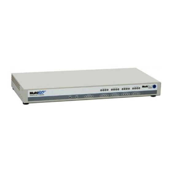
Overview MultiVOIP User Guide T1 Front Panel LEDs The MVP2400, MVP2410, and MVP24-48 all use a common main circuit board or motherboard. Consequently the LED indicators are the same for all. Figure 1-2. MultiVOIP MVP2400 Front Panel Active LEDs. The MVP2410 front panel has two sets of identical LEDs. -
Page 13: T1 Led Descriptions
Power Indicates presence of power. Boot After power up, the Boot LED will be on for about 10 seconds while the MVP2400/2410 is booting. Receive. Lights when receiving data on Ethernet port. Transmit. Lights when transmitting data on Ethernet port. -
Page 14: Introduction To Ei Multivoips (Mvp3010 & Mvp30-60)
MultiVOIP User Guide Introduction to EI MultiVOIPs (MVP3010 & MVP30-60) We proudly present MultiTech’s E1 Digital Multi-VOIP products. The MVP3010 is a rack-mount model and the MVP30-60 is an add-on expansion card that doubles the capacity of the MVP3010 without adding another chassis. - Page 15 MultiVOIP User Guide Overview H.323 Version 2). The fourth version of the H.323 standard improves system resource usage (esp. logical port or socket usage) by handling call signaling more compactly and allowing use of the low-overhead UDP protocol instead of the error-correcting TCP protocol where possible.
-
Page 16: E1 Front Panel Leds
Overview MultiVOIP User Guide E1 Front Panel LEDs Because the MVP3010 and MVP30-60 both use a common main circuit card or motherboard, the LED indicators are the same for both. Figure 1-4. MultiVOIP MVP3010 Chassis Active LEDs. The MVP3010 front panel has two sets of identical LEDs. In the MVP3010 as shipped (that is, without an expansion card), the left-hand set of LEDs is functional whereas the right-hand set is not. - Page 17 MultiVOIP User Guide Overview MVP3010 Front Panel LED Definitions (cont’d) T1. Not supported. E1. When lit, indicates presence of E1 connection. PRI. On if E1 line is of ISDN-Primary-Rate type. Online. This LED is on when frame synchronization has been established on the T1/E1 link.
-
Page 18: Introduction To Analog Multivoips (Mvp-210/410/810 & Mvp428)
Overview MultiVOIP User Guide Introduction to Analog MultiVOIPs (MVP-210/410/810 & MVP428) VOIP: The Free Ride. We proudly present Multi-Tech's MVP- 210/410/810 generation of MultiVOIP Voice-over-IP Gateways. They allow voice/fax communication to be transmitted at no additional expense over your existing IP network, which has ordinarily been data- only. - Page 19 MultiVOIP User Guide Overview H.323 specifications also bring to voip telephony many special features common to conventional telephony. H.323 features of this kind that have been implemented into the MuliVOIP include Call Hold, Call Waiting, Call Identification, Call Forwarding (from the H.450 standard), and Call Transfer (H.450.2 from H.323 Version 2).
-
Page 20: Analog Multivoip Front Panel Leds
Overview MultiVOIP User Guide Analog MultiVOIP Front Panel LEDs LED Types. The MultiVOIPs have two types of LEDs on their front panels: (1) general operation LED indicators (for power, booting, and ethernet functions), and (2) channel operation LED indicators which describe the data traffic and performance in each VOIP data channel. -
Page 21: Analog Multivoip Led Descriptions
MultiVOIP User Guide Overview Analog MultiVOIP LED Descriptions MVP-210/410/810 Front Panel LED Definitions DESCRIPTION LED NAME General Operation LEDs (one set on each MultiVOIP model) Power Indicates presence of power. Boot After power up, the Boot LED will be on briefly while the MultiVOIP is booting. -
Page 22: Computer Requirements
Overview MultiVOIP User Guide Computer Requirements The computer on which the MultiVOIP’s configuration program is installed must meet these requirements: must be IBM-compatible PC with MS Windows operating system; must have an available COM port for connection to the MultiVOIP. However, this PC does not need to be connected to the MultiVOIP permanently. -
Page 23: Specifications
MultiVOIP User Guide Overview Specifications Specs for Digital T1 MultiVOIP Units Digital T1 MultiVOIP Specifications Parameter MVP-2410 ……/Model w/ MVP24-48 MVP-2400 MVP-2410 Expansion Card Operating External 100-240 VAC 100-240 VAC Voltage(s) transformer: 1.2 - 0.6 A 1.2 - 0.6 A 1.6A@5v Mains 50/60 Hz... -
Page 24: Specs For Digital E1 Multivoip Units
Overview MultiVOIP User Guide Specs for Digital E1 MultiVOIP Units Digital E1 MultiVOIP Specifications Parameter MVP-3010 MVP-3010 ……/Model w/ MVP30-60 Expansion Card Operating 100-240 VAC 100-240 VAC Voltage(s) 1.2 - 0.6 A 1.2 - 0.6 A Mains 50/60 Hz 50/60 Hz Frequencies Power 17 watts... -
Page 25: Specs For Analog Multivoip Units
MultiVOIP User Guide Overview Specs for Analog MultiVOIP Units Analog MultiVOIP Specifications Parameter MVP210 MVP410 MVP810 ……/Model MVP410 + 428 External Operating 100-240 VAC 100-240 VAC Voltage(s) transformer: 1.2 - 0.6 A 1.2 - 0.6 A 3A @5V Mains 50/60 Hz 50/60 Hz 50/60 Hz Frequencies... -
Page 26: Installation At A Glance
Site: www.adobe.com/prodindex/acrobat/readstep.html This MultiVOIP User Guide is also available on Multi-Tech’s Web site http://www.multitech.com Viewing and printing a user guide from the Web also requires that you have the Acrobat Reader loaded on your system. To select the MultiVOIP User Guide from the Multi-Tech Systems home page, click Documents and then click MultiVOIP Family in the product list drop-down window. -
Page 27: Chapter 2: Quick Start Instructions
Chapter 2: Quick Start Instructions... -
Page 28: Introduction
Quick Start Instructions MultiVOIP User Guide Introduction This chapter gets the MultiVOIP up and running quickly. The details we’ve skipped to make this brief can be found elsewhere in the manual (see Table of Contents and Index). MultiVOIP Startup Tasks Task Summary Collecting Phone/IP... -
Page 29: Phone/Ip Details *Absolutely Needed* Before Starting The Installation
Gateway Domain Name Server (DNS) Info (not implemented; for future use) Gather Telephone Information T1 Phone Parameters Info needed to operate: MVP2400 Ask phone company or MVP2410 PBX maintainer. T1 Telephony Parameters: Record for this VOIP Site Which frame format is used? -
Page 30: Gather Telephone Information
Quick Start Instructions MultiVOIP User Guide Phone/IP Details *Absolutely Needed* (cont’d) Gather Telephone Information E1 Phone Parameters Info needed to operate: MVP3010 Ask phone company or PBX maintainer. E1 Telephony Parameters: Record for this VOIP Site Which frame format is used? _____ Double Frame MultiFrame w/ CRC4... -
Page 31: Obtain Email Address For Voip (For Email Call Log Reporting)
MultiVOIP User Guide Quick Start Instructions Phone/IP Details Often Needed/Wanted Obtain Email Address for VOIP (for email call log reporting) required if log reports of VOIP call traffic Optional are to be sent by email SMTP Parameters Preparation Task: To: I.T. Department Ask Mail Server re: email account for VOIP administrator to set up... -
Page 32: Placement
Quick Start Instructions MultiVOIP User Guide Placement Mount your MultiVOIP in a safe and convenient location where cables for your network and phone system are accessible. Rack-mounting instructions are in Chapter 3: Mechanical Installation & Cabling. The Command/Control Computer (Specs & Settings) The computer used for command and control of the MultiVOIP (a) must be an IBM-compatible PC, (b) must use a Microsoft operating system,... -
Page 33: Quick Hookups
MultiVOIP User Guide Quick Start Instructions Quick Hookups Hookup for MVP2410 & MVP3010 T1/E1 MultiVOIP Hookup (MVP-2410/3010) Grounding Screw Cabling to your IP network. RJ-45 connector. Cabling to computer running T1/E1/PRI cabling to your PBX, MultiVOIP software. and/or to the PSTN. RJ-45 to serial connector (DB9). - Page 34 Quick Start Instructions MultiVOIP User Guide Hookup for MVP2400 DIGITAL VOICE ETHERNET COMMAND Power Connection TRUNK 10/100 POWER RS232 Command Port Connection PSTN Telephony Connection Network Connection Hookup for MVP210 E&M RS232 E&M FXS/FXO FXS/FXO ETHERNET 10/100 COMMAND POWER...
-
Page 35: Load Multivoip Control Software Onto Pc
MultiVOIP User Guide Quick Start Instructions Load MultiVOIP Control Software onto PC For more details, see Chapter 4: Software Installation. 1. MultiVOIP must be properly cabled. Power must be turned on. 2. Insert MultiVOIP CD into drive. Allow 10-20 seconds for Autorun to start. -
Page 36: Phone/Ip Starter Configuration
Quick Start Instructions MultiVOIP User Guide Phone/IP Starter Configuration Full details here: MVP2400 Chapter 5: Technical Configuration for MVP2410 Digital T1/E1 MultiVOIPs MVP3010 MVP210 Chapter 6: Technical Configuration for MVP410 Analog MultiVOIPs MVP810 1. Open MultiVOIP program: Start | MultiVOIP xxx | Configuration. - Page 37 MultiVOIP User Guide Quick Start Instructions 5. Go to Configuration | Voice/Fax. Select Coder | “Automatic.” At the right-hand side of the dialog box, click Default. If you know any specific parameter values that will apply to your system, enter them. Click Copy Channel.
- Page 38 Quick Start Instructions MultiVOIP User Guide Phone/IP Starter Configuration (continued) 9. (continued) Whenever email log messages are sent out, they must have a standard Subject line. Something like “Phone Logs for Voip N” is useful. If you have more than one MultiVoip unit in the building, you’ll need a unique identifier for each one (select a useful name or number for “N”).
-
Page 39: Phonebook Starter Configuration (With Remote Voip)
MultiVOIP User Guide Quick Start Instructions Phonebook Starter Configuration (with remote voip) To do this part of the quick setup, you need to know of another voip that you can call to conduct a test. It should be at a remote location, typically somewhere outside of your building. - Page 40 Quick Start Instructions MultiVOIP User Guide 4. Suppose you want to call a phone number outside of your building using a phone station that is an extension from your PBX system (if present). What digits must you dial? Often a “9” or “8” must be dialed to “get an outside line”...
- Page 41 MultiVOIP User Guide Quick Start Instructions 5. In the “Destination Pattern” field of the Add/Edit Outbound Phonebook screen, enter the digits from step 4 followed by the digits from step 3. North America, Euro, National Call Long-Distance Example Example Seattle-Chicago system. London/Birming.
- Page 42 Quick Start Instructions MultiVOIP User Guide 6. Tally up the number of digits that must be dialed to reach the remote voip site (including prefix digits of all types). Enter this number in the “Total Digits” field. North America, Euro, National Call Long-Distance Example Example Seattle-Chicago system.
-
Page 43: Inbound Phonebook
MultiVOIP User Guide Quick Start Instructions field in the Outbound Phonebook. This precludes the problem of having to make two inbound phonebook entries at remote voips, one to account for situations where “8” is used as the PBX access digit, and another for when “9”... - Page 44 Quick Start Instructions MultiVOIP User Guide 4. In the “Add Prefix” field, enter any digits that must be dialed from your local voip to gain access to the PSTN. North America, Euro, National Call Long-Distance Example Example Seattle-Chicago system. London/Birming. system. On Seattle PBX, “9”...
- Page 45 MultiVOIP User Guide Quick Start Instructions 6. In the “Description” field, it is useful to describe the ultimate destination of the calls. For example, in a New York City voip system, “incoming calls to Manhattan office,” might describe a phonebook entry, as might the descriptor “incoming calls to NYC local calling area.”...
-
Page 46: Phonebook Tips
Quick Start Instructions MultiVOIP User Guide Phonebook Tips Preparing the phonebook for your voip system is a complex task that, at first, seems quite daunting. These tips may make the task easier. . You will not Use Dialing Patterns, Not Complete Phone Numbers generally enter complete phone numbers in the voip phonebook. - Page 47 MultiVOIP User Guide Quick Start Instructions . There are digits (PSTN access codes) that must be access codes dialed to gain access to an operator, to access the publicly switched ‘long-distance’ calling system(North America), to access the publicly switched ‘national’ calling system (Europe and elsewhere), or to access the publicly switched ‘international’...
- Page 48 Quick Start Instructions MultiVOIP User Guide Using a Comma Detail Commas are used in telephone dialing strings to indicate a pause = 1-second pause to allow a dial tone to appear (common on PBX and key in many PBX systems systems).
-
Page 49: Phonebook Example
MultiVOIP User Guide Quick Start Instructions Phonebook Example One Common Situation Boise Office Area: 208 Voip Example. This company has offices in three PBX System. Main Number: different cities. The PBX units all operate alike. 333-2700 PSTN Notably, they all give access to outside lines using “9.”... - Page 50 Quick Start Instructions MultiVOIP User Guide Boise Office Area: 208 Boise Voip Boise Voip PBX System. Inbound Phonebook Outbound Phonebook Main Number: Prefix to Prefix Description Destin. Total Prefix to Prefix Description 333-2700 to Add Incoming Calls Digits Remove to Add Addr Outgoing Calls Remove...
- Page 51 MultiVOIP User Guide Quick Start Instructions Sample Phonebooks Enlarged Boise Voip Boise Voip Inbound Phonebook Outbound Phonebook Prefix Description Total Prefix to Prefix Description Prefix to Destin. to Add Incoming Calls Digits Remove to Add Addr Outgoing Calls Remove Pattern 1208 Incoming calls 91505...
- Page 52 Quick Start Instructions MultiVOIP User Guide Phonebook Worksheet Voip Location/ID:____________________________ Inbound Phonebook Outbound Phonebook Prefix Description Total Prefix to Prefix Description Prefix to Destin. to Add Incoming Calls Digits Remove to Add Addr Outgoing Calls Remove Pattern Other Details: Voip Location/ID:____________________________ Inbound Phonebook Outbound Phonebook Prefix...
- Page 53 MultiVOIP User Guide Quick Start Instructions Enlarged Phonebook Worksheet...
-
Page 54: Connectivity Test
Quick Start Instructions MultiVOIP User Guide Connectivity Test The procedures “Phone/IP Starter Configuration” and “Phonebook Starter Configuration” must be completed before you can do this procedure. 1. These connections must be made: Connections for digital MultiVOIPs for analog MultiVOIPs (MVP-2400/2410/3010 (MVP-210/410/810) MultiVOIP to local PBX MultiVOIP to local phone... - Page 55 MultiVOIP User Guide Quick Start Instructions 6. Use HyperTerminal to receive and record console messages from the MultiVOIP unit. To do so, set up HyperTerminal as follows (setup shown is for Windows NT4; details will differ slightly in other MS operating systems): In the upper toolbar of the HyperTerminal screen, click on the Properties button.
- Page 56 Quick Start Instructions MultiVOIP User Guide 8. Read console messages recorded on HyperTerminal. Console Messages from Originating VOIP. The voip unit that originates the call will send back messages like that shown below. [00026975] CAS[0] : RX : ABCD = 1, 1, 1, 1,Pstn State[1] TimeStamp : 26975 [00027190] CAS[0] : TX : ABCD = 1, 1, 1, 1 [00027190] PSTN: cas seizure detected on 0...
- Page 57 MultiVOIP User Guide Quick Start Instructions Console Messages from Terminating VOIP. The voip unit connected to the phone where the call is answered will send back messages like that shown below. [00170860] H323[0]: New incoming call [00170860] PSTNIF : Placing call on channel 0 Outbound digit 7175662 [00170885] CAS[0] : TX : ABCD = 1, 1, 1, 1 [00171095] H323IF [0]: MasterSlaveStatus=Master...
-
Page 58: Troubleshooting
1. Ping both MultiVOIP units to confirm connectivity to the network. 2. Verify the telephone connections. A. For MVP2400, MVP2410, or MVP3010. Check cabling. Are connections well seated? To correct receptacle? Is the ONL LED on? (If on, ONL indicates that the MultiVOIP is online on the network.) -
Page 59: Chapter 3: Mechanical Installation And Cabling
Chapter 3: Mechanical Installation and Cabling... -
Page 60: Introduction
Mechanical Installation & Cabling MultiVOIP User Guide Introduction The MultiVOIP models MVP210 and MVP2400 are table-top units and can be handled easily by one person. However, the MVP410, MVP810, MVP2410, and MVP3010 are somewhat heavier units. When these units are to be installed into a rack, two able-bodied persons should participate. -
Page 61: Unpacking Your Multivoip
Study the particular illustration below that is appropriate to the model you have purchased. If any box contents are missing, contact MultiTech Tech Support at 1-800-972-2439. Unpacking the MVP2410/3010 Figure 3-1: Unpacking the MVP2410/3010... -
Page 62: Unpacking The Mvp2400
Mechanical Installation & Cabling MultiVOIP User Guide Unpacking the MVP2400 Voice/Fax over IP Networks Quick Start Guide Figure 3-2: Unpacking the MVP2400... -
Page 63: Unpacking The Mvp410/810
MultiVOIP User Guide Mechanical Installation & Cabling Unpacking the MVP410/810 Quick Start Voice/Fax over IP Networks Guide Voice/Fax 5 Voice/Fax 6 Voice/Fax 7 Voice/Fax 8 RC V Power Boot Ethernet Voice/Fax 1 Voice/Fax 2 Voice/Fax 3 Voice/Fax 4 RC V Figure 3-3: Unpacking the MVP410/810... -
Page 64: Unpacking The Mvp210
Mechanical Installation & Cabling MultiVOIP User Guide Unpacking the MVP210 Voice/Fax over IP Networks Quick Start Guide Figure 3-4: Unpacking the MVP210... -
Page 65: Rack Mounting Instructions For Mvp2410/3010 & Mvp410/810
MultiVOIP User Guide Mechanical Installation & Cabling Rack Mounting Instructions for MVP2410/3010 & MVP410/810 The MultiVOIPs can be mounted in an industry-standard EIA 19-inch rack enclosure, as shown in Figure 2-5. Figure 3-5: Rack-Mounting (MVP2410/3010 or MVP410/810) -
Page 66: Safety Recommendations For Rack Installations
Mechanical Installation & Cabling MultiVOIP User Guide Safety Recommendations for Rack Installations Ensure proper installation of the unit in a closed or multi-unit enclosure by following the recommended installation as defined by the enclosure manufacturer. Do not place the unit directly on top of other equipment or place other equipment directly on top of the unit. -
Page 67: 19-Inch Rack Enclosure Mounting Procedure
MultiVOIP User Guide Mechanical Installation & Cabling 19-Inch Rack Enclosure Mounting Procedure Attaching the MultiVOIP to a rack-rail of an EIA 19-inch rack enclosure will certainly require two persons. Essentially, the technicians must attach the brackets to the MultiVOIP chassis with the screws provided, as shown in Figure 3-6, and then secure unit to rack rails by the brackets, as shown in Figure 3-7. -
Page 68: Cabling
Mechanical Installation & Cabling MultiVOIP User Guide Cabling Cabling Procedure for MVP2410/3010 Cabling your MultiVOIP entails making the proper connections for power, command port, phone system (T1/E1 line connected to PBX or telco office), and Ethernet network. Figure 3-8 shows the back panel connectors and the associated cable connections. -
Page 69: Cabling Procedure For Mvp2400
PSTN Telephony Connection Network Connection Figure 3-9: Cabling for MVP2400 2. Connect the MultiVOIP to the PC (the computer that will hold the MultiVOIP software) using the RJ-45 to DB9 (female) cable provided with your unit. Plug the RJ-45 end of the cable into the Command port of the MultiVOIP and connect the other end (the DB9 connector) to the PC serial port you are using (typically COM1 or COM2). -
Page 70: Cabling Procedure For Mvp410/810
Mechanical Installation & Cabling MultiVOIP User Guide 3. Connect a network cable to the Ethernet connector on the back of the MultiVOIP. Connect the other end of the cable to your network. 4. Turn on power to the MultiVOIP by setting the power switch on the right side panel to the ON position. - Page 71 MultiVOIP User Guide Mechanical Installation & Cabling 3. Connect a network cable to the ETHERNET 10BASET connector on the back of the MultiVOIP. Connect the other end of the cable to your network. 4. If you are connecting a station device such as an analog telephone, a fax machine, or a Key Telephone System (KTS) (FXS interface), or a PBX extension (FXO interface) to your MultiVOIP, connect one end of an RJ-11 phone cord to the Channel 1 FXS/FXO connector on the back...
-
Page 72: Cabling Procedure For Mvp210
Mechanical Installation & Cabling MultiVOIP User Guide Cabling Procedure for MVP210 Cabling involves connecting the MultiVOIP to your LAN and telephone equipment. 1. Connect the power cord supplied with your MultiVOIP to the power connector on the back of the MultiVOIP and a live AC outlet as shown in Figure 3-11. - Page 73 MultiVOIP User Guide Mechanical Installation & Cabling will define the interface in the Interface dialog box in the software when you configure the unit. If you are connecting an E&M trunk from a telephone switch to your MultiVOIP, connect one end of an RJ-45 phone cord to the Channel 1 E&M connector on the back of the MultiVOIP and the other end to the trunk.
-
Page 74: Chapter 4: Software Installation
Chapter 4: Software Installation... -
Page 75: Introduction
MultiVOIP User Guide Software Installation Introduction Configuring software for your MultiVOIP entails three tasks: (1) loading the software onto the PC (this is “Software Installation and is discussed in this chapter), (2) setting values for telephony and IP parameters that will fit your system (this is “Technical Configuration”... - Page 76 Software Installation MultiVOIP User Guide 2. Insert the MultiVOIP CD into your CD-ROM drive. The CD should start automatically. It may take 10 to 20 seconds for the Multi-Tech CD installation window to display. If the Multi-Tech Installation CD window does not display automatically, click My Computer, then right click the CD ROM drive icon, click Open, and then click the Autorun icon.
- Page 77 MultiVOIP User Guide Software Installation 4. A ‘welcome’ screen appears. Press Enter or click Next to continue.
- Page 78 Software Installation MultiVOIP User Guide 5. Follow the on-screen instructions to install your MultiVOIP software. The first screen asks you to choose the folder location of the files of the MultiVOIP software. Choose a location and click Next.
- Page 79 MultiVOIP User Guide Software Installation 6. At the next screen, you must select a program folder location for the MultiVOIP software program icon. Click Next. Transient progress screens will appear while files are being copied.
- Page 80 Software Installation MultiVOIP User Guide 7. On the next screen you can select the COM port that the command PC will use when communicating with the MultiVoip unit. After software installation, the COM port can be re-set in the MultiVoip Software (from the sidebar menu, select Connection | Settings to access the COM Port Setup screen or use the keyboard shortcut Ctrl + G).
- Page 81 MultiVOIP User Guide Software Installation 8. A completion screen will appear. Click Finish. 9. When setup of the MultiVOIP software is complete, you will be prompted to run the MultiVOIP software to configure the VOIP. Software installation is complete at this point. You may proceed with Technical Configuration now or not, at your convenience.
-
Page 82: Un-Installing The Multivoip Configuration Software
Software Installation MultiVOIP User Guide Un-Installing the MultiVOIP Configuration Software 1. To un-install the MultiVOIP configuration software, go to Start | Programs and locate the entry for the MultiVOIP program. Select Uninstall. - Page 83 MultiVOIP User Guide Software Installation 2. Two confirmation screens will appear. Click Yes and OK when you are certain you want to continue with the uninstallation process. 3. A special warning message similar to that shown below may appear concerning the MultiVOIP software’s “.bin” file. Click Yes.
- Page 84 Software Installation MultiVOIP User Guide 4. A completion screen will appear. Click Finish.
-
Page 86: Chapter 5: Technical Configuration For Digital T1/E1 Multivoips (Mvp2400, Mvp2410, Mvp3010)
Chapter 5: Technical Configuration for Digital T1/E1 MultiVOIPs (MVP2400, MVP2410, MVP3010) -
Page 87: Configuring The Digital T1/E1 Multivoip
MultiVOIP User Guide Technical Configuration (Digital Voips) Configuring the Digital T1/E1 MultiVOIP There are two ways in which the MultiVOIP must be configured before operation: technical configuration and phonebook configuration. Technical Configuration. First, the MultiVOIP must be configured to operate with technical parameter settings that will match the equipment with which it interfaces. - Page 88 MultiVOIP configuration program. The MultiVoipManager program is on the MultiVOIP Product CD. Updates, when applicable, may be posted at on the MultiTech FTP site. To download, go to ftp://ftp.multitech.com/MultiVoip/. Web Browser Interface. The MultiVOIP web browser GUI gives access to the same commands and configuration parameters as are available in the MultiVOIP Windows GUI except for logging functions.
-
Page 89: Local Configuration
MultiVOIP User Guide Technical Configuration (Digital) Local Configuration This manual describes local configuration only. For information on remote configuration and management, see the MultiVoipManager documentation. Pre-Requisites To complete the configuration of the MultiVOIP unit, you must know several things about the overall system. Before configuring your MultiVOIP Gateway unit, you must know the values for several IP and T1/E1 parameters that describe the IP network system and telephony system (PBX or telco central office... -
Page 90: T1 Telephony Parameters (For Mvp2400 & Mvp2410)
MultiVOIP User Guide Technical Configuration (Digital Voips) T1 Telephony Parameters (for MVP2400 & MVP2410) The following parameters must be known about the PBX or telco central office equipment to which the T1 MultiVOIP will connect: T1 Phone Parameters Info needed to operate:... -
Page 91: E1 Telephony Parameters (For Mvp3010)
MultiVOIP User Guide Technical Configuration (Digital) E1 Telephony Parameters (for MVP3010) The following parameters must be known about the PBX or telco central office equipment to which the E1 MultiVOIP will connect: E1 Phone Parameters Info needed to operate: MVP3010 Ask phone company or PBX maintainer. -
Page 92: Smtp Parameters (For Email Call Log Reporting)
MultiVOIP User Guide Technical Configuration (Digital Voips) SMTP Parameters (for email call log reporting) required if log reports of VOIP call traffic Optional are to be sent by email SMTP Parameters Preparation Task: To: I.T. Department Ask Mail Server re: email account for VOIP administrator to set up email account (with password) for the... -
Page 93: Local Configuration Procedure (Summary)
MultiVOIP User Guide Technical Configuration (Digital) Local Configuration Procedure (Summary) After the MultiVOIP configuration software has been installed in the ‘Command’ PC (which is connected to the MultiVOIP unit), several steps must be taken to configure the MultiVOIP to function in its specific setting. -
Page 94: Local Configuration Procedure (Detailed)
MultiVOIP User Guide Technical Configuration (Digital Voips) Local Configuration Procedure (Detailed) You can begin the configuration process as a continuation of the MultiVOIP software installation. You can establish your configuration or modify it at any time by launching the MultiVOIP program from the Windows Start menu. - Page 95 MultiVOIP User Guide Technical Configuration (Digital) 3. Confirm Connection. If the MultiVOIP is set for an available COM port and is correctly cabled to the PC, the MultiVOIP main screen will appear. (If the main screen appears grayed out and seems inaccessible, go to step 4.)
- Page 96 MultiVOIP User Guide Technical Configuration (Digital Voips) In the lower left corner of the screen, the connection status of the MultiVOIP will be displayed. The messages in the lower left corner will change as detection occurs. The message “MultiVOIP Found” confirms that the MultiVOIP is in contact with the MultiVOIP configuration program.
- Page 97 MultiVOIP User Guide Technical Configuration (Digital) 4. Solving Common Connection Problems. A. Fixing a COM Port Problem. If the MultiVOIP main screen appears but is grayed out and seems inaccessible, the COM port that was specified for its communication with the PC is unavailable and must be changed.
- Page 98 MultiVOIP User Guide Technical Configuration (Digital Voips) 4B. Fixing a Cabling Problem. If the MultiVOIP cannot be located by the computer, two error messages will appear (saying “Multi-VOIP Not Found” and “Phone Database Not Read”). In this case, the MultiVOIP is simply disconnected from the network. For instructions on MultiVOIP cable connections, see the “Cabling”...
- Page 99 MultiVOIP User Guide Technical Configuration (Digital) 6. Set IP Parameters. This dialog box can be reached by pulldown menu, toolbar icon, keyboard shortcut, or sidebar. Accessing “IP Parameters” Pulldown Icon Shortcut Sidebar Ctrl + Alt + I...
- Page 100 MultiVOIP User Guide Technical Configuration (Digital Voips) In each field, enter the values that fit your particular network.
- Page 101 MultiVOIP User Guide Technical Configuration (Digital) The IP Parameters fields are described in the table below. IP Parameter Definitions Field Name Values Description Enable Diffserv is used for QoS Diffserv (quality of service). When enabled, we configure the TOS (Type of Service) bits in the IP header so routers supporting Diffserv can...
- Page 102 MultiVOIP User Guide Technical Configuration (Digital Voips) 7. Enable Web Browser GUI (Optional). After an IP address for the MultiVOIP unit has been established, you can choose to do any further configuration of the unit (a) by using the MultiVOIP web browser GUI, or (b) by continuing to use the MultiVOIP Windows GUI.
- Page 103 MultiVOIP User Guide Technical Configuration (Digital) 8. Set Voice/FAX Parameters. This dialog box can be reached by pulldown menu, toolbar icon, keyboard shortcut, or sidebar. Accessing “Voice/FAX Parameters” Pulldown Icon Shortcut Sidebar Ctrl + H...
- Page 104 MultiVOIP User Guide Technical Configuration (Digital Voips) In each field, enter the values that fit your particular network.
- Page 105 MultiVOIP User Guide Technical Configuration (Digital) Note that Voice/FAX parameters are applied on a channel-by-channel basis. However, once you have established a set of Voice/FAX parameters for a particular channel, you can apply this entire set of Voice/FAX parameters to another channel by using the Copy Channel button and its dialog box.
- Page 106 +3dB to Default value: -4 dB. Not to be High Tones -31dB & changed except under supervision of “mute” MultiTech’s Technical Support. DTMF Gain, +3dB to Default value: -7 dB. Not to be Low Tones -31dB & changed except under supervision of “mute”...
- Page 107 MultiVOIP User Guide Technical Configuration (Digital) Voice/Fax Parameter Definitions (cont’d) Field Name Values Description DTMF Parameters Duration 60 – 3000 When DTMF: Out of Band is (DTMF) selected, this setting determines how long each DTMF digit ‘sounds’ or is held. Default = 100 ms. DTMF Out of When DTMF Out of Band is selected...
- Page 108 MultiVOIP User Guide Technical Configuration (Digital Voips) Voice/Fax Parameter Definitions (cont’d) Coder Parameters Coder Manual or Determines whether selection of Auto- coder is manual or automatic. matic When Automatic is selected, the local and remote voice channels will negotiate the voice coder to be used by selecting the highest bandwidth coder supported by both sides without exceeding the Max...
- Page 109 MultiVOIP User Guide Technical Configuration (Digital) Voice/Fax Parameter Definitions (cont’d) Field Name Values Description Advanced Features Silence Determines whether silence Compression compression is enabled (checked) for this voice channel. With Silence Compression enabled, the MultiVOIP will not transmit voice packets when silence is detected, thereby reducing the amount of network bandwidth that is being used by the voice channel.
- Page 110 MultiVOIP User Guide Technical Configuration (Digital Voips) Voice/Fax Parameter Definitions (cont’d) Field Name Values Description Dynamic Jitter Dynamic Dynamic Jitter defines a minimum Jitter Buffer and a maximum jitter value for voice communications. When receiving voice packets from a remote , varying delays MultiVOIP between packets may occur due to...
- Page 111 MultiVOIP User Guide Technical Configuration (Digital) Voice/Fax Parameter Definitions (cont’d) Field Name Values Description Dynamic Jitter Maximum 60 to 400 The default maximum dynamic Jitter Value jitter buffer of 300 milliseconds is the maximum delay tolerable over a high jitter network. Default = 300 msec Optimizat- 0 to 12...
- Page 112 MultiVOIP User Guide Technical Configuration (Digital Voips) Voice/Fax Parameter Definitions (cont’d) ) Field Name Values Description Auto Disconnect Automatic The Automatic Disconnection Disconnect- group provides four options which can be used singly or in any combination. Jitter Value 1-65535 The Jitter Value defines the average milli- inter-arrival packet deviation (in seconds...
- Page 113 MultiVOIP User Guide Technical Configuration (Digital) 9. Set T1/E1/ISDN Parameters. This dialog box can be reached by pulldown menu, toolbar icon, keyboard shortcut, or sidebar. Accessing “T1/E1/ISDN Parameters” Pulldown Icon Shortcut Sidebar Ctrl + T...
- Page 114 MultiVOIP User Guide Technical Configuration (Digital Voips) In each field, enter the values that fit your particular network.
- Page 115 MultiVOIP User Guide Technical Configuration (Digital) T1 Parameters. The parameters applicable to T1 and their values are shown in the figure below. These T1 Parameter fields are described in the tables that follow.
- Page 116 MultiVOIP User Guide Technical Configuration (Digital Voips) T1 Parameter Definitions Field Name Values Description T1/E1/ISDN North American standard. Long-Haul In Long-Haul Mode, the MultiVOIP Mode auto-matically recovers received signals as low as –36 dB. The maximum reachable length with 22 AWG cable is 2000 meters.
- Page 117 MultiVOIP User Guide Technical Configuration (Digital) T1 Parameter Definitions (cont’d) Field Name Values Description CAS Protocol E&M Immed Strt Channel Associated Signaling E&M Wink Start (CAS) is a method of incorporating telephony E&M Wink with signaling info into a T1 dial tone voice/data stream.
- Page 118 MultiVOIP User Guide Technical Configuration (Digital Voips) T1 Parameter Definitions (cont’d) ISDN Parameters Field Name Values Description Enable If digital connection is ISDN- ISDN-PRI PRI type, this box should be checked. When ISDN is enabled, the “CAS Protocols” field is grayed out (ISDN has its own signaling method).
-
Page 119: Pending
MultiVOIP User Guide Technical Configuration (Digital) T1 Parameter Definitions (cont’d) Field Name Values Description Line Build Out 0 dB, -7.5 dB, To reduce the crosstalk on -15 dB, -22.5 dB received signals, a transmit attenuator can be placed in the data path. - Page 120 MultiVOIP User Guide Technical Configuration (Digital Voips) E1 Parameters. The parameters applicable to E1 and their values are shown in the figure below. These E1 Parameter fields are described in the tables that follow.
- Page 121 MultiVOIP User Guide Technical Configuration (Digital) E1 Parameter Definitions Field Name Values Description T1/E1/ISDN European standard. Long-Haul In Long-Haul Mode, the MultiVOIP Mode auto-matically recovers received signals as low as –36 dB. The maximum reachable length with 22 AWG cable is 2000 meters. When Long-Haul Mode is disabled, signals as low as –10 dB can be received.
- Page 122 MultiVOIP User Guide Technical Configuration (Digital Voips) E1 Parameter Definitions (cont’d) Field Name Values Description CAS Protocol E&M Immed Strt Channel Associated Signaling E&M Wink Start (CAS) is a method of incorporating telephony E&M Wink with signaling info into an E1 dial tone voice/data stream.
- Page 123 MultiVOIP User Guide Technical Configuration (Digital) E1 Parameter Definitions (cont’d) ISDN Parameters Field Name Values Description Enable If digital connection is ISDN- ISDN-PRI PRI type, this box should be checked. When ISDN is enabled, the “CAS Protocols” field is grayed out (ISDN has its own signaling method).
- Page 124 MultiVOIP User Guide Technical Configuration (Digital Voips) E1 Parameter Definitions (cont’d) Field Name Values Description Line Build Out 0 dB, -7.5 dB, To reduce the crosstalk on -15 dB, -22.5 dB received signals, a transmit attenuator can be placed in the data path.
- Page 125 MultiVOIP User Guide Technical Configuration (Digital) 10. Set ISDN Parameters (if applicable). These parameters are acces- sible in the T1/E1/ISDN Parameters screen. If your T1 or E1 phone line is a Primary Rate Interface ISDN line, enable ISDN-PRI and set it for the particular implementation of ISDN that your telco uses.
- Page 126 MultiVOIP User Guide Technical Configuration (Digital Voips) 11. Set SNMP Parameters (Remote Voip Management). This dialog box can be reached by pulldown menu, keyboard shortcut, or sidebar. To make the MultiVOIP controllable by a remote PC running the MultiVoipManager software, check the “Enable SNMP Agent”...
- Page 127 MultiVOIP User Guide Technical Configuration (Digital) In each field, enter the values that fit your particular system.
- Page 128 MultiVOIP User Guide Technical Configuration (Digital Voips) The SNMP Parameter fields are described in the table below. SNMP Parameter Definitions Field Name Values Description Enable SNMP Enables the SNMP code in the MultiVOIP Agent firmware of the . This MultiVOIP must be enabled for the to communicate with and be controllable by the...
- Page 129 MultiVOIP User Guide Technical Configuration (Digital) 12. Set Regional Parameters (Phone Signaling Tones & Cadences). This dialog box can be reached by pulldown menu, keyboard shortcut, or sidebar. Accessing “Regional Parameters” Pulldown Icon Shortcut Sidebar Ctrl + R...
- Page 130 MultiVOIP User Guide Technical Configuration (Digital Voips) The Regional Parameters screen will appear. For the country selected, the standard set of frequency pairs will be listed for dial tone, busy tone, ‘unobtainable’ tone (fast busy or trunk busy), and ring tone. In each field, enter the values that fit your particular system.
- Page 131 MultiVOIP User Guide Technical Configuration (Digital) The Regional Parameters fields are described in the table below. “Regional Parameter” Definitions Field Name Values Description Country/ USA, Japan, UK, Name of a country or region that uses a certain set of tone pairs for Region Custom dial tone, ring tone, busy tone, and...
- Page 132 MultiVOIP User Guide Technical Configuration (Digital Voips) “Regional Parameter” Definitions (cont’d) Field Name Values Description Cadence n/n/n/n On/off pattern of tone durations (msec) On/Off four integer time used to denote phone ringing, values in phone busy, connection milli-seconds; unobtainable (fast busy), and dial zero value for tone (continuous and described as dial-tone...
- Page 133 MultiVOIP User Guide Technical Configuration (Digital) 13. Set Custom Tones and Cadences (optional) . The Regional Parameters dialog box has a secondary dialog box that allows you to customize DTMF tone pairs to create unique ring-tones, dial-tones, busy-tones or “unobtainable” tones (fast busy signal) for your system. This screen allows the user to specify tone-pair attributes that are not found in any of the standard national/regional telephony toning schemes.
- Page 134 MultiVOIP User Guide Technical Configuration (Digital Voips) The Custom Tone-Pair Settings fields are described in the table below. Custom Tone-Pair Settings Definitions Field Name Values Description dial tone Identifies the type of telephony Tone Pair busy tone signaling tone for which ring tone, frequencies are being specified.
- Page 135 MultiVOIP User Guide Technical Configuration (Digital) Custom Tone-Pair Settings Definitions Field Name Values Description Cadence 1 integer time On/off pattern of tone durations value in used to denote phone ringing, milli-seconds; phone busy, connection zero value for unobtainable tone (fast busy), dial-tone and dial tone (which is indicates...
- Page 136 MultiVOIP User Guide Technical Configuration (Digital Voips) 14. Set SMTP Parameters (Log Reports by Email). The SMTP Parameters screen is applicable when the VOIP administrator has chosen to receive log reports by email (this is done by selecting the “SMTP” checkbox in the Others screen and selecting “Enable SMTP” in the SMTP Parameters screen.).
- Page 137 MultiVOIP User Guide Technical Configuration (Digital) The SMTP Parameters screen is shown below. “SMTP Parameters” Definitions Field Name Values Description Enable SMTP In order to send log reports by email, this box must be checked. However, to enable SMTP functionality, you must also select “SMTP”...
- Page 138 MultiVOIP User Guide Technical Configuration (Digital Voips) ..“SMTP Parameters” Definitions (cont’d) Field Name Values Description Mail Type text or html Mail type in which log reports will be sent. Subject text User specified. Subject line that will appear for all emailed log reports for this MultiVOIP unit.
- Page 139 MultiVOIP User Guide Technical Configuration (Digital) The SMTP Parameters dialog box has a secondary dialog box, Custom Fields, that allows you to customize email log messages for the MultiVOIP. The MultiVOIP software logs data about many aspects of the call traffic going through the MultiVOIP. The Custom Fields screen lets you pick which aspects will be included in the email log reports.
- Page 140 MultiVOIP User Guide Technical Configuration (Digital Voips) “Custom Fields” Definitions (cont’d) Field Description Field Description Digits put out by Prefix When selected, the Outbound Digits MultiVOIP onto Matched phonebook prefix the T1 or E1 line. matched in processing call will be listed in log.
- Page 141 MultiVOIP User Guide Technical Configuration (Digital)
- Page 142 MultiVOIP User Guide Technical Configuration (Digital Voips) 15. Set Log Reporting Method. The Logs screen lets you choose how the VoIP administrator will receive log reports about the MultiVOIP’s performance and the phone call traffic that is passing through it. Log reports can be received in one of three ways: A.
- Page 143 MultiVOIP User Guide Technical Configuration (Digital) Select the logging option that applies to your VoIP system design. If you intend to use a SysLog Server program for logging, click in that Enable check box. The common SysLog logical port number is 514. If you intend to use the MultiVOIP web browser GUI for configuration and control of MultiVOIP units, be aware that the web browser GUI does not support logs directly.
- Page 144 MultiVOIP User Guide Technical Configuration (Digital Voips) SNMP Log messages will be delivered to the MultiVoipManager application program. SMTP Log messages will be sent to user- specified email address. SysLog Server This box must be checked if logging is to Enable be done in conjunction with a SysLog Server program.
- Page 145 MultiVOIP User Guide Technical Configuration (Digital) 16. Set Supplementary Services Parameters. This dialog box can be reached by pulldown menu, keyboard shortcut, or sidebar. Accessing “Supplementary Services Parameters” Pulldown Icon Shortcut Sidebar Ctrl + Alt +H Supplementary Services features derive from the H.450 standard, which brings to voip telephony functionality once only available with PSTN or PBX telephony.
- Page 146 MultiVOIP User Guide Technical Configuration (Digital Voips) In each field, enter the values that fit your particular network. Of the features implemented under Supplementary Services, three are very closely related: Call Transfer, Call Hold, and Call Waiting. Call Name Identification is similar but not identical to the premium PSTN feature commonly known as Caller ID.
- Page 147 MultiVOIP User Guide Technical Configuration (Digital) the channel over which the call is being originated (for example, “Calling Party - Omaha Sales Office Line 2”). If that voip channel is dedicated to a certain individual, the descriptor could say that, as well (for example “Calling Party - Harold Smith in Omaha”).
- Page 148 MultiVOIP User Guide Technical Configuration (Digital Voips) The Supplementary Services fields are described in the tables below. Supplementary Services Parameter Definitions Field Name Values Description Select The channel to be configured is 1-2 (210); Channel selected here. 1-4 (410); 1-8 (810) Call Select to enable the Call Transfer Transfer...
- Page 149 MultiVOIP User Guide Technical Configuration (Digital) Supplementary Services Definitions (cont’d) Field Name Values Description Call Hold Select to enable Call Hold function in Enable voip unit. Call Hold allows one party to maintain an idle (non-talking) connection with another party while receiving another call (Call Waiting), while initiating another call (Call Transfer), or while performing some...
- Page 150 MultiVOIP User Guide Technical Configuration (Digital Voips) Supplementary Services Definitions (cont’d) Field Name Values Description Call Name Enables CNI function. Call Name Identification is not the same as Caller Identification Enable ID. When enabled on a given voip unit currently being controlled by the MultiVOIP GUI (the ‘home voip’), Call Name Identification sends an identifier and status information to...
- Page 151 MultiVOIP User Guide Technical Configuration (Digital) Supplementary Services Definitions (cont’d) Field Name Values Description Calling If the ‘home’ voip unit is originating Party, the call and Calling Party is selected, Allowed then the identifier (from the Caller Id Name Type field) will be sent to the remote voip (CNI) unit being called.
- Page 152 MultiVOIP User Guide Technical Configuration (Digital Voips) Supplementary Services Definitions (cont’d) Field Name Values Description Alerting If the ‘home’ voip unit is receiving the Party, call and Alerting Party is selected, Allowed then the identifier (from the Caller Id Name Type field) will tell the originating remote (CNI) voip unit that the call is ringing.
- Page 153 MultiVOIP User Guide Technical Configuration (Digital) Supplementary Services Definitions (cont’d) Field Name Values Description Busy Party, If the ‘home’ voip unit is receiving a Allowed call directed toward an already Name Type engaged channel or phone station and (CNI) Busy Party is selected, then the identifier (from the Caller Id field) will tell the originating remote voip unit that the channel or called party is...
- Page 154 MultiVOIP User Guide Technical Configuration (Digital Voips) Supplementary Services Definitions (cont’d) Field Name Values Description Connected If the ‘home’ voip unit is receiving a Party, call and Connected Party is selected, Allowed then the identifier (from the Caller Id Name Type field) will tell the originating remote (CNI) voip unit that the attempted call has...
- Page 155 MultiVOIP User Guide Technical Configuration (Digital) Supplementary Services Definitions (cont’d) Field Name Values Description Caller ID This is the identifier of a specific channel of the ‘home’ voip unit. The Caller Id field typically describes a person, office, or location, for example, “Harry Smith,”...
- Page 156 MultiVOIP User Guide Technical Configuration (Digital Voips) 17. Set Baud Rate. The Connection option in the sidebar menu has a “Settings” item that includes the baud-rate setting for the COM port of the computer running the MultiVOIP software. First, it is important to note that the default COM port established by the MultiVOIP program is COM1.
- Page 157 MultiVOIP User Guide Technical Configuration (Digital) 18. View System Information screen and set updating interval (optional). This dialog box can be reached by pulldown menu, keyboard shortcut, or sidebar. Accessing the “System Information” Screen Pulldown Icon Shortcut Sidebar Ctrl + Alt +Y...
- Page 158 MultiVOIP User Guide Technical Configuration (Digital Voips) This screen presents vital system information at a glance. It’s primary use is in troubleshooting. System Information Parameter Definitions Field Name Values Description Boot Code Indicates the version of the code that nn.nn Version is used at the startup (booting) of the voip.
- Page 159 MultiVOIP User Guide Technical Configuration (Digital) The frequency with which the System Information screen is updated is determined by a setting in the Logs screen 19. Saving the MultiVOIP Configuration. When values have been set for all of the MultiVOIP’s various operating parameters, click on Save Setup in the sidebar.
- Page 160 MultiVOIP User Guide Technical Configuration (Digital Voips) 20. Creating a User Default Configuration. When a “Setup” (complete grouping of parameters) is being saved, you will be prompted about designating that setup as a “User Default” setup. A User Default setup may be useful as a baseline of site-specific values to which you can easily revert.
-
Page 161: Chapter 6: Technical Configuration For Analog Multivoips (Mvp210/410/810)
Chapter 6: Technical Configuration for Analog MultiVOIPs (MVP210/410/810) -
Page 162: Configuring The Analog Multivoip
MultiVOIP User Guide Technical Configuration (Analog) Configuring the Analog MultiVOIP There are two ways in which the MultiVOIP must be configured before operation: technical configuration and phonebook configuration. Technical Configuration. First, the MultiVOIP must be configured to operate with technical parameter settings that will match the equipment with which it interfaces. - Page 163 MultiVOIP configuration program. The MultiVoipManager program is on the MultiVOIP Product CD. Updates, when applicable, may be posted at on the MultiTech FTP site. To download, go to ftp://ftp.multitech.com/MultiVoip/. Web Browser Interface. The MultiVOIP web browser GUI gives access to the same commands and configuration parameters as are available in the MultiVOIP Windows GUI except for logging functions.
- Page 164 MultiVOIP User Guide Technical Configuration (Analog) WARNING: Do not attempt to interface the MultiVOIP unit with two control programs simultaneously (that is, by accessing the MultiVOIP configuration program via the Command Port and either the MultiVoipManager program or the web browser interface via the Ethernet Port).
-
Page 165: Local Configuration
MultiVOIP User Guide Technical Configuration (Analog) Local Configuration This manual describes local configuration only. For information on remote configuration and management, see the MultiVoipManager documentation. Pre-Requisites To complete the configuration of the MultiVOIP unit, you must know several things about the overall system. Before configuring your MultiVOIP Gateway unit, you must know the values for several IP and telephone parameters that describe the IP network system and telephony system (PBX or telco central office... -
Page 166: Analog Telephony Interface Parameters (For Mvp210/410/810)
MultiVOIP User Guide Technical Configuration (Analog) Analog Telephony Interface Parameters (for MVP210/410/810) The following parameters must be known about the PBX or telco central office equipment to which the analog MultiVOIP will connect: : Analog Phone Parameters Needed for: MVP810 Ask phone company or MVP410 telecom manager. -
Page 167: Smtp Parameters (For Email Call Log Reporting)
MultiVOIP User Guide Technical Configuration (Analog) SMTP Parameters (for email call log reporting) required if log reports of VOIP call traffic Optional are to be sent by email SMTP Parameters Preparation Task: To: I.T. Department Ask Mail Server re: email account for VOIP administrator to set up email account (with password) for the... -
Page 168: Local Configuration Procedure (Summary)
MultiVOIP User Guide Technical Configuration (Analog) Local Configuration Procedure (Summary) After the MultiVOIP configuration software has been installed in the ‘Command’ PC (which is connected to the MultiVOIP unit), several steps must be taken to configure the MultiVOIP to function in its specific setting. -
Page 169: Local Configuration Procedure (Detailed)
MultiVOIP User Guide Technical Configuration (Analog) Local Configuration Procedure (Detailed) You can begin the configuration process as a continuation of the MultiVOIP software installation. You can establish your configuration or modify it at any time by launching the MultiVOIP program from the Windows Start menu. - Page 170 MultiVOIP User Guide Technical Configuration (Analog) 3. Confirm Connection. If the MultiVOIP is set for an available COM port and is correctly cabled to the PC, the MultiVOIP main screen will appear. (If the main screen appears grayed out and seems inaccessible, go to step 4.)
- Page 171 MultiVOIP User Guide Technical Configuration (Analog) In the lower left corner of the screen, the connection status of the MultiVOIP will be displayed. The messages in the lower left corner will change as detection occurs. The message “MultiVOIP Found” confirms that the MultiVOIP is in contact with the MultiVOIP configuration program.
- Page 172 MultiVOIP User Guide Technical Configuration (Analog) 4. Solving Common Connection Problems. . A. Fixing a COM Port Problem. If the MultiVOIP main screen appears but is grayed out and seems inaccessible, the COM port that was specified for its communication with the PC is unavailable and must be changed.
- Page 173 MultiVOIP User Guide Technical Configuration (Analog) 4B. Fixing a Cabling Problem. If the MultiVOIP cannot be located by the computer, two error messages will appear (saying “Multi-VOIP Not Found” and “Phone Database Not Read”). In this case, the MultiVOIP is simply disconnected from the network. For instructions on MultiVOIP cable connections, see the Cabling section of Chapter 3.
- Page 174 MultiVOIP User Guide Technical Configuration (Analog) 6. Set IP Parameters. This dialog box can be reached by pulldown menu, toolbar icon, keyboard shortcut, or sidebar. Accessing “IP Parameters” Pulldown Icon Shortcut Sidebar Ctrl + Alt + I...
- Page 175 MultiVOIP User Guide Technical Configuration (Analog) In each field, enter the values that fit your particular network.
- Page 176 MultiVOIP User Guide Technical Configuration (Analog) The IP Parameters fields are described in the table below. IP Parameter Definitions Field Name Values Description Enable Diffserv is used for QoS Diffserv (quality of service). When enabled, we configure the TOS (Type of Service) bits in the IP header so routers supporting Diffserv can...
- Page 177 MultiVOIP User Guide Technical Configuration (Analog) 7. Enable Web Browser GUI (Optional). After an IP address for the MultiVOIP unit has been established, you can choose to do any further configuration of the unit (a) by using the MultiVOIP web browser GUI, or (b) by continuing to use the MultiVOIP Windows GUI.
- Page 178 MultiVOIP User Guide Technical Configuration (Analog) 8. Set Voice/FAX Parameters. This dialog box can be reached by pulldown menu, toolbar icon, keyboard shortcut, or sidebar. Accessing “Voice/FAX Parameters” Pulldown Icon Shortcut Sidebar Ctrl + H...
- Page 179 MultiVOIP User Guide Technical Configuration (Analog) In each field, enter the values that fit your particular network.
- Page 180 MultiVOIP User Guide Technical Configuration (Analog) Note that Voice/FAX parameters are applied on a channel-by-channel basis. However, once you have established a set of Voice/FAX parameters for a particular channel, you can apply this entire set of Voice/FAX parameters to another channel by using the Copy Channel button and its dialog box.
- Page 181 +3dB to Default value: -4 dB. Not to be High Tones -31dB & changed except under supervision of “mute” MultiTech’s Technical Support. DTMF Gain, +3dB to Default value: -7 dB. Not to be Low Tones -31dB & changed except under supervision of “mute”...
- Page 182 MultiVOIP User Guide Technical Configuration (Analog) Voice/Fax Parameter Definitions (cont’d) Field Name Values Description DTMF Parameters Duration 60 – 3000 When DTMF: Out of Band is (DTMF) selected, this setting determines how long each DTMF digit ‘sounds’ or is held. Default = 100 ms. DTMF Out of When DTMF Out of Band is...
- Page 183 MultiVOIP User Guide Technical Configuration (Analog) Voice/Fax Parameter Definitions (cont’d) Coder Parameters Coder Manual or Determines whether selection of Auto- coder is manual or automatic. matic When Automatic is selected, the local and remote voice channels will negotiate the voice coder to be used by selecting the highest bandwidth coder supported by both sides without exceeding the Max...
- Page 184 MultiVOIP User Guide Technical Configuration (Analog) Voice/Fax Parameter Definitions (cont’d) Field Name Values Description Advanced Features Silence Determines whether silence Compression compression is enabled (checked) for this voice channel. With Silence Compression enabled, the MultiVOIP will not transmit voice packets when silence is detected, thereby reducing the amount of network bandwidth that is being used by the voice channel.
- Page 185 MultiVOIP User Guide Technical Configuration (Analog) Voice/Fax Parameter Definitions (cont’d) ) Field Name Values Description Dynamic Jitter Dynamic Dynamic Jitter defines a minimum Jitter Buffer and a maximum jitter value for voice communications. When receiving voice packets from a remote , varying delays MultiVOIP between packets may occur due to...
- Page 186 MultiVOIP User Guide Technical Configuration (Analog) Voice/Fax Parameter Definitions (cont’d) Field Name Values Description Dynamic Jitter Maximum 60 to 400 The maximum dynamic jitter buffer Jitter Value of 400 milliseconds is the maximum delay tolerable over a high jitter network. Default = 300 msec Optimizat- 0 to 12...
- Page 187 MultiVOIP User Guide Technical Configuration (Analog) Voice/Fax Parameter Definitions (cont’d) ) Field Name Values Description Auto Disconnect Automatic The Automatic Disconnection Disconnect- group provides four options which can be used singly or in any combination. Jitter Value 1-65535 The Jitter Value defines the average milli- inter-arrival packet deviation (in seconds...
- Page 188 MultiVOIP User Guide Technical Configuration (Analog) 9. Set Telephony Interface Parameters. This dialog box can be reached by pulldown menu, toolbar icon, keyboard shortcut, or sidebar. Accessing Telephony Interface Parameters Pulldown Icon Shortcut Sidebar Ctrl + I...
- Page 189 MultiVOIP User Guide Technical Configuration (Analog) In each field, enter the values that fit your particular network. The kinds of parameters for which values must be chosen depend on the type of telephony supervisory signaling or interface used (FXO, E&M, etc.). We present here the various parameters grouped and organized by interface type.
- Page 190 MultiVOIP User Guide Technical Configuration (Analog) FXS Loop Start Parameters. The parameters applicable to FXS Loop Start are shown in the figure below and described in the table that follows. FXS Loop Start Interface: Parameter Definitions Field Name Values Description FXS Loop Start Enables FXS Loop Start interface type.
- Page 191 MultiVOIP User Guide Technical Configuration (Analog) FXS Loop Start Interface: Parameter Definitions Field Name Values Description Message Applicable only when Waiting Light MultiVOIP is used with Avaya Magix PBX units equipped with Merlin Messaging Centralized mail. When enabled, the Message Waiting Light feature allows the PBX to send mode- codes and message-waiting indications to another Avaya...
- Page 192 MultiVOIP User Guide Technical Configuration (Analog) FXS Ground Start Parameters (not supported). The parameters applicable to FXS Ground Start are shown in the figure below and described in the table that follows. FXS Ground Start Interface: Parameter Definitions Field Name Values Description FXS Ground...
- Page 193 MultiVOIP User Guide Technical Configuration (Analog) allows Direct Inward Dialing, such that no additional dial tone is needed on voip call. Maximum number of rings that Ring Count, integer values the MultiVOIP will issue before giving up the attempted call. When enabled, the MultiVOIP FXS Options, will interrupt loop current in...
- Page 194 MultiVOIP User Guide Technical Configuration (Analog) FXO Parameters. The parameters applicable to the FXO telephony interface type are shown in the figure below and described in the table that follows.
- Page 195 MultiVOIP User Guide Technical Configuration (Analog) FXO Interface: Parameter Definitions Field Name Values Description Interface, FXO Enables FXO functionality Dialing Options Regeneration Pulse, DTMF Determines whether digits generated and sent out will be pulse tones or DTMF. Inter Digit integer values, This is the length of time that Timer in seconds...
- Page 196 MultiVOIP User Guide Technical Configuration (Analog) FXO Interface: Parameter Definitions (cont’d) Field Name Values Description Dialing Options (cont’d) Inter Digit milliseconds The length of time between the Regeneration outputting of DTMF digits. Time Default = 100 ms. FXO Disconnect On There are three possible criteria for disconnection under FXO: current loss, tone detection, and...
- Page 197 MultiVOIP User Guide Technical Configuration (Analog) FXO Interface: Parameter Definitions (cont’d) Field Name Values Description FXO Disconnect On (cont’d) Disconnect tone pair These are DTMF tone pairs. Tone Sequence Values for first tone pair are: tone pair *, #, 0, 1-9, and A-D. Values for second tone pair are: none, 0, 1-9, A-D, *, and #.
- Page 198 MultiVOIP User Guide Technical Configuration (Analog) E&M Parameters. The parameters applicable to the E&M telephony interface type are shown in the figure below and described in the table that follows.
- Page 199 MultiVOIP User Guide Technical Configuration (Analog) E&M Interface Parameter Definitions Field Name Values Description Interface E&M enables E&M functionality Type Types 1-5. Each Refers to the type of E&M type can be 2- interface being used. wire or 4-wire. Signal Dial Tone or When Dial Tone is selected, no Wink...
- Page 200 MultiVOIP User Guide Technical Configuration (Analog) 10. Set SNMP Parameters (Remote Voip Management). This dialog box can be reached by pulldown menu, keyboard shortcut, or sidebar. To make the MultiVOIP controllable by a remote PC running the MultiVoipManager software, check the “Enable SNMP Agent”...
- Page 201 MultiVOIP User Guide Technical Configuration (Analog) In each field, enter the values that fit your particular system.
- Page 202 MultiVOIP User Guide Technical Configuration (Analog) The SNMP Parameter fields are described in the table below. SNMP Parameter Definitions Field Name Values Description Enable SNMP Enables the SNMP code in the MultiVOIP Agent firmware of the . This MultiVOIP must be enabled for the to communicate with and be controllable by the MultiVoipManager software.
- Page 203 MultiVOIP User Guide Technical Configuration (Analog) 11. Set Regional Parameters (Phone Signaling Tones & Cadences). ). This dialog box can be reached by pulldown menu, keyboard shortcut, or sidebar. Accessing “Regional Parameters” Pulldown Icon Shortcut Sidebar Ctrl + R...
- Page 204 MultiVOIP User Guide Technical Configuration (Analog) The Regional Parameters screen will appear. For the country selected, the standard set of frequency pairs will be listed for dial tone, busy tone, ‘unobtainable’ tone (fast busy or trunk busy), and ring tone. In each field, enter the values that fit your particular system.
- Page 205 MultiVOIP User Guide Technical Configuration (Analog) The Regional Parameters fields are described in the table below. “Regional Parameter” Definitions Field Name Values Description Country/ USA, Japan, UK, Name of a country or region that uses a certain set of tone pairs for Region Custom dial tone, ring tone, busy tone, and...
- Page 206 MultiVOIP User Guide Technical Configuration (Analog) “Regional Parameter” Definitions (cont’d) Field Name Values Description Cadence n/n/n/n On/off pattern of tone durations (msec) On/Off four integer time used to denote phone ringing, values in phone busy, connection milli-seconds; unobtainable (fast busy), and dial zero value for tone (“0”...
- Page 207 MultiVOIP User Guide Technical Configuration (Analog) 12. Set Custom Tones and Cadences (optional). . The Regional Parameters dialog box has a secondary dialog box that allows you to customize DTMF tone pairs to create unique ring-tonesdial-tones, busy-tones or “unobtainable” tones (fast busy signal) for your system. This screen allows the user to specify tone-pair attributes that are not found in any of the standard national/regional telephony toning schemes.
- Page 208 MultiVOIP User Guide Technical Configuration (Analog) The Custom Tone-Pair Settings fields are described in the table below. Custom Tone-Pair Settings Definitions Field Name Values Description Tone Pair dial tone, Identifies the type of telephony busy tone, signaling tone for which ring tone, frequencies are being specified.
- Page 209 MultiVOIP User Guide Technical Configuration (Analog) Custom Tone-Pair Settings Definitions Field Name Values Description Cadence 1 integer time On/off pattern of tone durations value in used to denote phone ringing, milli-seconds; phone busy, and dial tone (“0” zero value for indicates continuous tone).
- Page 210 MultiVOIP User Guide Technical Configuration (Analog) 13. Set SMTP Parameters (Log Reports by Email). The SMTP Parameters screen is applicable when the VOIP administrator has chosen to receive log reports by email (this is done by selecting the “SMTP” checkbox in the Others screen and selecting “Enable SMTP” in the SMTP Parameters screen.).
- Page 211 MultiVOIP User Guide Technical Configuration (Analog) The SMTP Parameters screen is shown below. . “SMTP Parameters” Definitions Field Name Values Description Enable SMTP In order to send log reports by email, this box must be checked. However, to enable SMTP functionality, you must also select “SMTP”...
- Page 212 MultiVOIP User Guide Technical Configuration (Analog) ..“SMTP Parameters” Definitions (cont’d) Field Name Values Description Mail Type text or html Mail type in which log reports will be sent. Subject text User specified. Subject line that will appear for all emailed log reports for this MultiVOIP unit.
- Page 213 MultiVOIP User Guide Technical Configuration (Analog) The SMTP Parameters dialog box has a secondary dialog box, Custom Fields, that allows you to customize email log messages for the MultiVOIP. The MultiVOIP software logs data about many aspects of the call traffic going through the MultiVOIP. The Custom Fields screen lets you pick which aspects will be included in the email log reports.
- Page 214 MultiVOIP User Guide Technical Configuration (Analog) “Custom Fields” Definitions (cont’d) Field Description Field Description Digits put out by Prefix When selected, the Outbound Digits MultiVOIP onto Matched phonebook prefix the phone line. matched in processing the call will be listed in log. Call Successful or Status...
- Page 215 MultiVOIP User Guide Technical Configuration (Analog)
- Page 216 MultiVOIP User Guide Technical Configuration (Analog) 14. Set Log Reporting Method. The Logs screen lets you choose how the VoIP administrator will receive log reports about the MultiVOIP’s performance and the phone call traffic that is passing through it. Log reports can be received in one of three ways: A.
- Page 217 MultiVOIP User Guide Technical Configuration (Analog) Select the logging option that applies to your VoIP system design. If you intend to use a SysLog Server program for logging, click in that Enable check box. The common SysLog logical port number is 514. If you intend to use the MultiVOIP web browser GUI for configuration and control of MultiVOIP units, be aware that the web browser GUI does not support logs directly.
- Page 218 MultiVOIP User Guide Technical Configuration (Analog) “Logs” Screen Definitions Field Name Values Description Enable Allows MultiVOIP debugging messages Console to be read via a basic terminal program Messages like HyperTerminal ™ or equivalent. Normally, this should be disabled because it uses MultiVOIP processing resources.
- Page 219 MultiVOIP User Guide Technical Configuration (Analog) 15. Set Supplementary Services Parameters. This dialog box can be reached by pulldown menu, keyboard shortcut, or sidebar. Accessing “Supplementary Services” Parameters Pulldown Icon Shortcut Sidebar Ctrl + Alt +H Supplementary Services features derive from the H.450 standard, which brings to voip telephony functionality once only available with PSTN or PBX telephony.
- Page 220 MultiVOIP User Guide Technical Configuration (Analog) In each field, enter the values that fit your particular network. Of the features implemented under Supplementary Services, three are very closely related: Call Transfer, Call Hold, and Call Waiting. Call Name Identification is similar but not identical to the premium PSTN feature commonly known as Caller ID.
- Page 221 MultiVOIP User Guide Technical Configuration (Analog) the channel over which the call is being originated (for example, “Calling Party - Omaha Sales Office Line 2”). If that voip channel is dedicated to a certain individual, the descriptor could say that, as well (for example “Calling Party - Harold Smith in Omaha”).
- Page 222 MultiVOIP User Guide Technical Configuration (Analog) The Supplementary Services fields are described in the tables below. Supplementary Services Parameter Definitions Field Name Values Description Select The channel to be configured is 1-2 (210); Channel selected here. 1-4 (410); 1-8 (810) Call Select to enable the Call Transfer Transfer...
- Page 223 MultiVOIP User Guide Technical Configuration (Analog) Supplementary Services Definitions (cont’d) Field Name Values Description Call Hold Select to enable Call Hold function in Enable voip unit. Call Hold allows one party to maintain an idle (non-talking) connection with another party while receiving another call (Call Waiting), while initiating another call (Call Transfer), or while performing some...
- Page 224 MultiVOIP User Guide Technical Configuration (Analog) Supplementary Services Definitions (cont’d) Field Name Values Description Call Name Enables CNI function. Call Name Identification is not the same as Caller Identification Enable ID. When enabled on a given voip unit currently being controlled by the MultiVOIP GUI (the ‘home voip’), Call Name Identification sends an identifier and status information to...
- Page 225 MultiVOIP User Guide Technical Configuration (Analog) Supplementary Services Definitions (cont’d) Field Name Values Description Calling If the ‘home’ voip unit is originating Party, the call and Calling Party is selected, Allowed then the identifier (from the Caller Id Name Type field) will be sent to the remote voip (CNI) unit being called.
- Page 226 MultiVOIP User Guide Technical Configuration (Analog) Supplementary Services Definitions (cont’d) Field Name Values Description Alerting If the ‘home’ voip unit is receiving the Party, call and Alerting Party is selected, Allowed then the identifier (from the Caller Id Name Type field) will tell the originating remote (CNI) voip unit that the call is ringing.
- Page 227 MultiVOIP User Guide Technical Configuration (Analog) Supplementary Services Definitions (cont’d) Field Name Values Description Busy Party, If the ‘home’ voip unit is receiving a Allowed call directed toward an already Name Type engaged channel or phone station and (CNI) Busy Party is selected, then the identifier (from the Caller Id field) will tell the originating remote voip unit that the channel or called party is...
- Page 228 MultiVOIP User Guide Technical Configuration (Analog) Supplementary Services Definitions (cont’d) Field Name Values Description Connected If the ‘home’ voip unit is receiving a Party, call and Connected Party is selected, Allowed then the identifier (from the Caller Id Name Type field) will tell the originating remote (CNI) voip unit that the attempted call has...
- Page 229 MultiVOIP User Guide Technical Configuration (Analog) Supplementary Services Definitions (cont’d) Field Name Values Description Caller ID This is the identifier of a specific channel of the ‘home’ voip unit. The Caller Id field typically describes a person, office, or location, for example, “Harry Smith,”...
- Page 230 MultiVOIP User Guide Technical Configuration (Analog) 16. Set Baud Rate. The Connection option in the sidebar menu has a “Settings” item that includes the baud-rate setting for the COM port of the computer running the MultiVOIP software. First, it is important to note that the default COM port established by the MultiVOIP program is COM1.
- Page 231 MultiVOIP User Guide Technical Configuration (Analog) 17. View System Information screen and set updating interval (optional). This dialog box can be reached by pulldown menu, keyboard shortcut, or sidebar. Accessing “System Information” Screen Pulldown Icon Shortcut Sidebar Ctrl + Alt +Y...
- Page 232 MultiVOIP User Guide Technical Configuration (Analog) This screen presents vital system information at a glance. It’s primary use is in troubleshooting. System Information Parameter Definitions Field Name Values Description Boot Code Indicates the version of the code that nn.nn Version is used at the startup (booting) of the voip.
- Page 233 MultiVOIP User Guide Technical Configuration (Analog) The frequency with which the System Information screen is updated is determined by a setting in the Logs screen 18. Saving the MultiVOIP Configuration. When values have been set for all of the MultiVOIP’s various operating parameters, click on Save Setup in the sidebar.
- Page 234 MultiVOIP User Guide Technical Configuration (Analog) 19. Creating a User Default Configuration. When a “Setup” (complete grouping of parameters) is being saved, you will be prompted about designating that setup as a “User Default” setup. A User Default setup may be useful as a baseline of site-specific values to which you can easily revert.
-
Page 235: Chapter 7: T1 Phonebook Configuration
Chapter 7: T1 Phonebook Configuration (North American Telephony Standards) -
Page 236: Configuring The Mvp2400/2410 Multivoip Phonebooks
Configuring the MVP2400/2410 MultiVOIP Phonebooks When a VoIP serves a PBX system, it’s important that the operation of the VoIP be transparent to the telephone end user. That is, the VoIP should not entail the dialing of extra digits to reach users elsewhere on the network that the VoIP serves. - Page 237 MultiVOIP User Guide T1 PhoneBook Configuration and terminating in New York City but off the company’s premises in an adjacent area code, an area code different than the company’s office but still a local call from that office (e.g., Staten Island). The first type of call requires an entry in the Outbound PhoneBook of the Miami VOIP and a coordinated entry in the Inbound phonebook of the New York VOIP.
- Page 238 E1 Phonebook Configuration MultiVOIP User Guide Phonebook configuration screens can be accessed using icons or the sidebar menu. Phonebook Icons Description Phonebook Configuration Inbound Phonebook Entries List Add Inbound Phonebook Entry Edit selected Inbound Phonebook Entry Outbound Phonebook Entries List Add Outbound Phonebook Entry Edit selected Outbound...
- Page 239 MultiVOIP User Guide T1 PhoneBook Configuration Phonebook Sidebar Menu 1. Go to the PhoneBook Configuration screen (using either the sidebar or drop-down menu).
- Page 240 E1 Phonebook Configuration MultiVOIP User Guide In consultation with your VOIP administrator, enter the Gateway Name and values for Q.931 parameters and Gatekeeper RAS parameters. Determine whether your voip system will operate with a proxy server. Determine which H.323 version 4 functions you will implement.
- Page 241 MultiVOIP User Guide T1 PhoneBook Configuration The table below describes all fields in the PhoneBook Configuration screen. PhoneBook Configuration Parameter Definitions Field Name Values Description Gateway This field allows you to specify Name a name for this MultiVOIP. When placing a call, this name is sent to the remote MultiVOIP for display in Call Progress listings, Logs, etc.
- Page 242 E1 Phonebook Configuration MultiVOIP User Guide PhoneBook Configuration Parameter Definitions (cont’d) Field Name Values Description Proxy Server Parameters Enable Proxy Allows the MultiVOIP to work in conjunction with a proxy server. Proxy Server n.n.n.n Network address of the proxy IP Address where server that the voip is using.
- Page 243 MultiVOIP User Guide T1 PhoneBook Configuration PhoneBook Configuration Parameter Definitions (cont’d) Field Name Values Description H.323 Version 4 Parameters FS (Fast Start or Fast Connect) Parallel H.245 is a Q.931 feature of H.323v2 to (FS + Tun) hasten call setup as well as ‘pre-opening’...
- Page 244 E1 Phonebook Configuration MultiVOIP User Guide 2. Select PhoneBook Modify and then select Outbound Phone Book/List Entries. Click Add.
- Page 245 T1 PhoneBook Configuration 3. The Add/Edit Outbound PhoneBook screen appears. Enter Outbound PhoneBook data for your MVP2400/2410. Note that the Advanced button gives access to the Alternate IP Routing feature, if needed. Alternate IP Routing can be implemented in a secondary...
- Page 246 E1 Phonebook Configuration MultiVOIP User Guide The fields of the Add/Edit Outbound Phone Book screen are described in the table below. Add/Edit Outbound Phone Book: Field Definitions Field Name Values Description Destination prefixes, Defines the beginning of Pattern area codes, dialing sequences for calls exchanges, that will be connected to...
- Page 247 MultiVOIP User Guide T1 PhoneBook Configuration Add/Edit Outbound Phone Book: Field Definitions (cont’d) Field Name Values Description H.323 fields Indicates whether or not Use Gatekeepr gatekeeper is used. The H.323 ID assigned to the H.323 ID destination MultiVOIP. Only valid if “Use Gatekeeper” is enabled for this entry.
- Page 248 E1 Phonebook Configuration MultiVOIP User Guide Add/Edit Outbound Phone Book: Field Definitions (cont’d) Field Name Values Description SIP Fields Use Proxy Select if proxy server is used. Transport TCP or Voip administrator must choose Protocol between UDP and TCP transmission protocols. UDP is a high-speed, low-overhead connectionless protocol where data is transmitted without...
- Page 249 MultiVOIP User Guide T1 PhoneBook Configuration Gives access to secondary Advanced button screen where an Alternate IP Route can be specified for backup or redundancy of signal paths. See discussion on next page. Clicking on the Advanced button brings up the Alternate Routing secondary screen. This feature provides an alternate path for calls if the primary IP network cannot carry the traffic.
- Page 250 E1 Phonebook Configuration MultiVOIP User Guide Alternate Routing Field Definitions Field Values Description Name Alternate n.n.n.n Alternate destination for outbound data traffic where in case of excessive delay in data transmission. Address n= 0-255 Round milliseconds The Round Trip Delay is the criterion for Trip judging when a data pathway is considered Delay...
- Page 251 MultiVOIP User Guide T1 PhoneBook Configuration 4. Select PhoneBook Modify and then select Inbound PhoneBook/List Entries.
- Page 252 E1 Phonebook Configuration MultiVOIP User Guide 5. The Add/Edit Inbound PhoneBook screen appears. Enter Inbound PhoneBook data for your MultiVOIP. The fields of the Add/Edit Inbound PhoneBook screen are described in the table below. Add/Edit Inbound Phone Book: Field Definitions Field Name Values Description...
- Page 253 MultiVOIP User Guide T1 PhoneBook Configuration Add/Edit Inbound Phone Book: Field Definitions (cont’d) Field Name Values Description Description Describes the facility or geographical location at which the call originated. Call Forward Parameters Enable Click the check-box to enable the call-forwarding feature. .
-
Page 254: T1 Phonebook Examples
Remember that the initial MVP2400/2410 setup must be done locally using the MultiVOIP program. However, after the initial configuration is complete, all of the MVP2400/2410 units in the VOIP system can be configured, re-configured, and updated from one location using the MultiVoipManager software program. - Page 255 MultiVOIP User Guide T1 PhoneBook Configuration An outline of the equipment setup in both offices is shown below. Local-Call Area Codes: 612, 651, Company HQ. Minneapolis North Sub. area 763 Digital VoIP -5174 200.2.10.3 -5173 -5172 -5171 717-5170 Network Overlay Area Code: Baltimore Sales Ofc.
- Page 256 E1 Phonebook Configuration MultiVOIP User Guide The screen below shows Outbound PhoneBook entries for the VOIP located in the company’s Baltimore facility. The entries in the Minneapolis VOIP’s Inbound PhoneBook match the Outbound PhoneBook entries of the Baltimore VOIP, as shown below.
- Page 257 MultiVOIP User Guide T1 PhoneBook Configuration To call the Minneapolis/St. Paul area, a Baltimore employee must dial eleven digits. (In this case, we are assuming that the Baltimore PBX does not require an “8” or “9” to seize an outside phone line.) If a Baltimore employee dials any phone number in the 612 area code, the call will automatically be handled by the company’s voip system.
- Page 258 E1 Phonebook Configuration MultiVOIP User Guide Similarly, the Inbound PhoneBook for the Baltimore VOIP (shown first below) generally matches the Outbound PhoneBook of the Minneapolis VOIP (shown second below). Notice the extended prefix to be removed: 14103257. This entry allows Minneapolis users to contact Baltimore co-workers as though they were in the Minneapolis facility, using numbers in the range 7000 to 7999.
- Page 259 MultiVOIP User Guide T1 PhoneBook Configuration The Outbound PhoneBook for the Minneapolis VOIP is shown below. The third destination pattern, “7” facilitates reception of co-worker calls using local-appearing-extensions only. In this case, the “Add Prefix” field value for this phonebook entry would be “1410325” .
-
Page 260: Configuring Mixed Digital/Analog Voip Systems
In addition to MVP-210/410/810 MultiVOIP units (Series II units), legacy analog VOIP units (Series I units made by MultiTech) may be included in the system, as well. When legacy VOIP units are included, the VOIP administrator must handle two styles of phonebooks in the same VOIP network. - Page 261 MultiVOIP User Guide T1 PhoneBook Configuration The Series I analog VOIP phone book resides in the “Host” VOIP unit at Site B. It applies to both of the Series I analog VOIP units. Each of the Series II analog MultiVOIPs (the MVP210 and the MVP410) requires its own inbound and outbound phonebooks.
- Page 262 E1 Phonebook Configuration MultiVOIP User Guide These seven phone books are shown below. Phone Book for Series I Analog VOIP Host Unit (Site B) VOIP Dir # IP Address Channel Comments -OR- Destination Pattern 200.2.9.8 Site B, FXS channel. 200.2.9.8 Site B, FXO channel.
-
Page 263: Reserved
Note 1. The “x” is a wildcard character. Note 2. By specifying “Channel 0,” we instruct the MVP2400/2410 to choose any available data channel to carry the call. Note 3. Note that Site F key system has only 30 extensions (x7400-7429). - Page 264 E1 Phonebook Configuration MultiVOIP User Guide Outbound Phone Book for MVP2400 Digital VOIP (Site D) Destin. Remove Comment Pattern Prefix Prefix Address 200.2.9.7 To originate calls to Site A (Bismarck). 1507 1507 101# 200.2.9.8 To originate calls to Rochester local Note 3.
- Page 265 MultiVOIP User Guide T1 PhoneBook Configuration Inbound Phonebook for MVP2400/2410 Digital VOIP (Site D) Remove Channel Comment Prefix Prefix Number 1615 Allows phone users at remote Note 4. voip sites to call non-toll Note 5. numbers within the Site D area code (615;...
- Page 266 E1 Phonebook Configuration MultiVOIP User Guide Outbound Phone Book for MVP410 Analog VOIP (Site F) Destin. Remove Comment Pattern Prefix Prefix Address 200.2.9.7 To originate calls to Site A (Bismarck). 1507 1507 101# 200.2.9.8 To originate calls to any PSTN Note 3.
- Page 267 MultiVOIP User Guide T1 PhoneBook Configuration Inbound Phonebook for MVP410 Analog VOIP (Site F) Remove Channel Comment Prefix Prefix Number 1402 Access to Lincoln local PSTN by users at remote VOIP locations via FXO port at Site F. 1402 Gives remote voip users access 263740 to extension of key phone 1402...
- Page 268 E1 Phonebook Configuration MultiVOIP User Guide Outbound Phone Book for MVP210 Analog VOIP (Site E) Destin. Remove Comment Pattern Prefix Prefix Address 200.2.9.7 To originate calls to Site A. 1507 1507 101# 200.2.9.8 To originate calls to any PSTN Note 3. phone in Rochester area using the FXO...
- Page 269 MultiVOIP User Guide T1 PhoneBook Configuration Inbound Phonebook for MVP210 Analog VOIP (Site E) Remove Channel Comment Prefix Prefix Number...
-
Page 270: Call Completion Summaries
E1 Phonebook Configuration MultiVOIP User Guide Call Completion Summaries Site A calling Site C, Method 1 Dial 101. Hear dial-tone from Site B. Dial 7175662. Await completion. Talk. Site A calling Site C, Method 2 Dial 101#7175662 Await completion. Talk. Note: Some analog VOIP gateways will allow completion by Method 2. - Page 271 507 into the VOIP network, but it may not be desirable to do so.) The MVP2400/2410 removes the prefix “1507” and adds the prefix “101#” for compatibility with the analog MultiVOIP’s phonebook scheme.
- Page 272 E1 Phonebook Configuration MultiVOIP User Guide Site D calling Site F A voip call from Pierre PBX to extension 7424 on the key telephone system in Lincoln, Nebraska. A. The required entry in the Pierre Outbound Phonebook to facilitate origination of the call, would be 1402263742. The call would be directed to the Lincoln voip’s IP address, 200.2.9.5.
-
Page 273: Variations In Pbx Characteristics
Variations in PBX Characteristics The exact dialing strings needed in the Outbound and Inbound Phonebooks of the MVP2400/2410 will depend on the capabilities of the PBX. Some PBXs require trunk access codes (like an “8” or “9” to access an outside line or to access the VOIP network). Other PBXs can automatically distinguish between intra-PBX calls, PSTN calls, and VOIP calls. -
Page 274: Chapter 8: E1 Phonebook Configuration
E1 Phonebook Configuration MultiVOIP User Guide Chapter 8: E1 Phonebook Configuration (European Telephony Standards) -
Page 275: Mvp3010 Inbound And Outbound Multivoip Phonebooks
MultiVOIP User Guide T1 PhoneBook Configuration MVP3010 Inbound and Outbound MultiVOIP Phonebooks Important The MultiVOIP’s Outbound phonebook Definition: lists the phone stations it can call; its Inbound phonebook describes the dialing sequences that can be used to call that MultiVOIP and how those calls will be directed. -
Page 276: Free Calls: One Voip Site To Another
E1 Phonebook Configuration MultiVOIP User Guide Free Calls: One VOIP Site to Another The most direct use of the VOIP system is making calls between the offices where the VOIPs are located. Consider, for example, the Wren Clothing Company. This company has VOIP-equipped offices in London, Paris, and Amsterdam, each served by its own PBX. -
Page 277: Local Rate Calls: Within Local Calling Area Of Remote Voip
MultiVOIP User Guide T1 PhoneBook Configuration Local Rate Calls: Within Local Calling Area of Remote VOIP In the second use of the VOIP system, the local calling area of each VOIP location becomes accessible to all of the VOIP system’s users. As a result, international calls can be made at local calling rates. - Page 278 E1 Phonebook Configuration MultiVOIP User Guide Similarly, the VOIP system allows Wren Clothing employees in London and Amsterdam to call anywhere in Paris at local rates; it allows Wren Clothing employees in Paris and London to call anywhere in Amsterdam at local rates. United Kingdom Wren Clothing Co.
-
Page 279: National Rate Calls: Within Nation Of Remote Voip Site
MultiVOIP User Guide T1 PhoneBook Configuration National Rate Calls: Within Nation of Remote VOIP Site In the third use of the VOIP system, the national calling area of each VOIP location becomes accessible to all of the VOIP system’s users. As a result, international calls can be made at national calling rates. -
Page 280: Inbound Versus Outbound Phonebooks
E1 Phonebook Configuration MultiVOIP User Guide Similarly, the VOIP system allows Wren Clothing employees in London and Amsterdam to call anywhere in France at French national rates; it allows Wren Clothing employees in Paris and Amsterdam to call anywhere in the United Kingdom at its national rates. United Kingdom Wren Clothing Co. - Page 281 MultiVOIP User Guide T1 PhoneBook Configuration In order for any VOIP phone call to be made, there must be both an Inbound Phonebook entry and an Outbound Phonebook entry that describe the end-to-end connection. The phone station originating the call must be connected to the VOIP system. The Outbound Phonebook for that VOIP unit must have a destination pattern entry that includes the ‘called’...
- Page 282 E1 Phonebook Configuration MultiVOIP User Guide Phonebook configuration screens can be accessed using icons or the sidebar menu. Phonebook Icons Description Phonebook Configuration Inbound Phonebook Entries List Add Inbound Phonebook Entry Edit selected Inbound Phonebook Entry Outbound Phonebook Entries List Add Outbound Phonebook Entry Edit selected Outbound...
- Page 283 MultiVOIP User Guide T1 PhoneBook Configuration Phonebook Sidebar Menu...
-
Page 284: Phonebook Configuration Procedure
E1 Phonebook Configuration MultiVOIP User Guide Phonebook Configuration Procedure 1. Go to the PhoneBook Configuration screen (using either the sidebar menu, drop-down menu, or icon). In consultation with your VOIP administrator, enter the Gateway Name and values for Q.931 parameters and Gatekeeper RAS parameters. - Page 285 MultiVOIP User Guide T1 PhoneBook Configuration The table below describes all fields in the PhoneBook Configuration screen. PhoneBook Configuration Parameter Definitions Field Name Values Description Gateway This field allows you to specify a name for Name this MultiVOIP. When placing a call, this name is sent to the remote MVP3000 for display in Call Progress listings, Logs, etc.
- Page 286 E1 Phonebook Configuration MultiVOIP User Guide PhoneBook Configuration Parameter Definitions (cont’d) Field Name Values Description Proxy Server Parameters Enable Proxy Proxy Server n.n.n.n Network address of the proxy IP Address where server that the voip is using. n=0-255 Port Number Logical port number for proxy communications.
- Page 287 MultiVOIP User Guide T1 PhoneBook Configuration PhoneBook Configuration Parameter Definitions (cont’d) Field Name Values Description H.323 Version 4 Parameters FS (Fast Start or Fast Connect) Parallel H.245 is a Q.931 feature of H.323v2 to (FS + Tun) hasten call setup as well as ‘pre-opening’...
- Page 288 E1 Phonebook Configuration MultiVOIP User Guide 2. Select PhoneBook Modify and then select Outbound Phone Book/List Entries. Click Add.
- Page 289 MultiVOIP User Guide T1 PhoneBook Configuration 3. The Add/Edit Outbound PhoneBook screen appears. Enter Outbound PhoneBook data for your MVP3010. Note that the Advanced button gives access to the Alternate IP Routing feature, if needed. Alternate IP Routing can be implemented in a secondary screen (as described after the primary screen field definitions below).
- Page 290 E1 Phonebook Configuration MultiVOIP User Guide The fields of the Add/Edit Outbound Phone Book screen are described in the table below. Add/Edit Outbound Phone Book: Field Definitions Field Name Values Description Destination prefixes, Defines the beginning of Pattern area codes, dialing sequences for calls exchanges, that will be connected to...
- Page 291 MultiVOIP User Guide T1 PhoneBook Configuration Add/Edit Outbound Phone Book: Field Definitions (cont’d) Field Name Values Description H.323 fields Indicates whether or not Use Gatekeepr gatekeeper is used. The H.323 ID assigned to the H.323 ID destination MultiVOIP. Only valid if “Use Gatekeeper” is enabled for this entry.
- Page 292 E1 Phonebook Configuration MultiVOIP User Guide Add/Edit Outbound Phone Book: Field Definitions (cont’d) Field Name Values Description SIP Fields Use Proxy Select if proxy server is used. Transport TCP or Voip administrator must choose Protocol between UDP and TCP transmission protocols. UDP is a high-speed, low-overhead connectionless protocol where data is transmitted without...
- Page 293 MultiVOIP User Guide T1 PhoneBook Configuration Gives access to secondary Advanced button screen where an Alternate IP Route can be specified for backup or redundancy of signal paths. See discussion on next page. Clicking on the Advanced button brings up the Alternate Routing secondary screen. This feature provides an alternate path for calls if the primary IP network cannot carry the traffic.
- Page 294 E1 Phonebook Configuration MultiVOIP User Guide Alternate Routing Field Definitions Field Values Description Name Alternate n.n.n.n Alternate destination for outbound data traffic where in case of excessive delay in data transmission. Address n= 0-255 Round milliseconds The Round Trip Delay is the criterion for Trip judging when a data pathway is considered Delay...
- Page 295 MultiVOIP User Guide T1 PhoneBook Configuration 4. Select PhoneBook Modify and then select Inbound PhoneBook/List Entries.
- Page 296 E1 Phonebook Configuration MultiVOIP User Guide 5. The Add/Edit Inbound PhoneBook screen appears. Enter Inbound PhoneBook data for your MVP3010. The fields of the Add/Edit Inbound PhoneBook screen are described in the table below. Add/Edit Inbound Phone Book: Field Definitions Field Values Description...
- Page 297 MultiVOIP User Guide T1 PhoneBook Configuration Add/Edit Inbound Phone Book: Field Definitions (cont’d) Field Name Values Description Description Describes the facility or geographical location at which the call originated. Call Forward Parameters Enable Click the check-box to enable the call-forwarding feature. .
-
Page 298: E1 Phonebook Examples
E1 Phonebook Configuration MultiVOIP User Guide 6. When your Outbound and Inbound PhoneBook entries are completed, click on Save Setup in the sidebar menu to save your configuration. You can change your configuration at any time as needed for your system. - Page 299 MultiVOIP User Guide T1 PhoneBook Configuration France Country Code: 33 Lille Paris: Area 01 Reims Rouen Nantes Strasbourg Lyon Bordeaux Toulouse Marseille...
- Page 300 E1 Phonebook Configuration MultiVOIP User Guide The Netherlands Country Code: 31 Groningen Leeuwarden Texel 0222 Den Helder 0223 038 Zwolle 0299 Purmerend Beverwijk 0251 Haarlem 023 020 Amsterdam Aalsmeer0297 0294 Weesp Enschede The Hague Arnhem Rotterdam 0118 Middelburg Eindhoven Maastricht...
- Page 301 MultiVOIP User Guide T1 PhoneBook Configuration An outline of the equipment setup in these three offices is shown below. Wren Clothing Co. London Office Country Code: +44 Area Code: 0208 Digital VoIP -5174 200.2.10.3 -5173 -5172 -5171 Network 979-5170 Wren Clothing Co. Paris Office Country Code: +33 Area Code: 01...
- Page 302 E1 Phonebook Configuration MultiVOIP User Guide The screen below shows Outbound PhoneBook entries for the VOIP located in the company’s London facility The Inbound PhoneBook for the London VOIP is shown below. NOTE: Commas are allowed in the Inbound Phonebook, but not in the Outbound Phonebook.
- Page 303 MultiVOIP User Guide T1 PhoneBook Configuration The screen below shows Outbound PhoneBook entries for the VOIP located in the company’s Paris facility. The Inbound PhoneBook for the Paris VOIP is shown below.
- Page 304 E1 Phonebook Configuration MultiVOIP User Guide The screen below shows Outbound PhoneBook entries for the VOIP in the company’s Amsterdam facility. The Inbound PhoneBook for the Amsterdam VOIP is shown below.
-
Page 305: Configuring Digital & Analog Voips In Same System
In addition to MVP-210/410/810 MultiVOIP units (Series II units), legacy analog VOIP units (Series I units made by MultiTech) may be included in the system, as well. When legacy VOIP units are included, the VOIP administrator must handle two styles of phonebooks in the same VOIP network. - Page 306 E1 Phonebook Configuration MultiVOIP User Guide The Series I analog VOIP phone book resides in the “Host” VOIP unit at Site B. It applies to both of the Series I analog VOIP units. Each of the Series II analog MultiVOIPs (the MVP210 and the MVP410) requires its own inbound and outbound phonebooks.
- Page 307 MultiVOIP User Guide T1 PhoneBook Configuration These seven phone books are shown below. Phone Book for Analog VOIP Host Unit (Site B) VOIP Dir # IP Address Channel Comments -OR- Destination Pattern 200.2.9.8 Site B, FXS channel. (Reading, UK) 200.2.9.8 Site B, FXO channel.
-
Page 308: Reserved
E1 Phonebook Configuration MultiVOIP User Guide 0208 200.2.9.9 Gives remote voip users (Note 2.) access to phone numbers xxxx in 0208 area code (Outer London) for which calls are local from Site D (Inner London). Note 1. The “x” is a wildcard character. Note 2. - Page 309 MultiVOIP User Guide T1 PhoneBook Configuration The Outbound PhoneBook of the MVP3010 is shown below. Outbound Phone Book for MVP3010 Digital VOIP (Site D) Destin. Remov Comment Pattern Prefix Address Prefix 200.2.9.7 To originate calls to Site A (Birmingham). 901189 901189 101# 200.2.9.8...
- Page 310 E1 Phonebook Configuration MultiVOIP User Guide The Inbound PhoneBook of the MVP3010 is shown below. Inbound Phone Book for MVP3010 Digital VOIP (Site D) Remove Channel Comments Prefix Prefix Number 0207 Allows phone users at remote voip sites Note 4. to call local numbers (those within the Note 5.
- Page 311 MultiVOIP User Guide T1 PhoneBook Configuration Outbound Phone Book for MVP410 Analog VOIP (Site F) Destin. Remove Comment Pattern Prefix Prefix Address 200.2.9.7 To originate calls to Site A (Birmingham). 01189 0118 101# 200.2.9.8 To originate calls to any PSTN Note 3.
- Page 312 E1 Phonebook Configuration MultiVOIP User Guide Inbound Phonebook for MVP410 Analog VOIP (Site F) Remove Channel Comment Prefix Prefix Number 01822 Calls to Tavistock local PSTN through FXO port (Port #4) at Site F. 0182 Gives remote voip users, access to extensions of key phone system atTavistock office.
- Page 313 MultiVOIP User Guide T1 PhoneBook Configuration Outbound Phone Book for MVP210 Analog VOIP (Site E) Destin. Remove Comment Pattern Prefix Prefix Address 200.2.9.7 To originate calls to Site A (Birmingham). 01189 0118 101# 200.2.9.8 To originate calls to any PSTN Note 3.
-
Page 314: Call Completion Summaries
E1 Phonebook Configuration MultiVOIP User Guide Inbound Phonebook for MVP210 Analog VOIP (Site E) Remove Channel Comment Prefix Prefix Number Call Completion Summaries Site A calling Site C, Method 1 Dial 101. Hear dial-tone from Site B. Dial 9435632. Await completion. Talk. Site A calling Site C, Method 2 Dial 101#9435632 Await completion. - Page 315 MultiVOIP User Guide T1 PhoneBook Configuration Site D calling Site C 1. Dial 901189435632. 2. “9” gets outside line. On some PBXs, an “8” may be used to direct calls to the VOIP, while “9” directs calls to the PSTN. However, some PBX units can be programmed to identify the destination patterns of all calls to be directed to the VOIP.
- Page 316 E1 Phonebook Configuration MultiVOIP User Guide Site D calling Site F A voip call from Inner London PBX to extension 7424 on the key telephone system in Tavistock, UK. A. The required entry in the London Outbound Phonebook to facilitate origination of the call, would be 90182263742.
-
Page 317: Variations In Pbx Characteristics
MultiVOIP User Guide T1 PhoneBook Configuration Site F calling Site D A voip call from a Tavistock key extension to extension 3117 on the PBX in Inner London. A. The required entry in the Tavistock Outbound Phonebook to facilitate origination of the call, would be “3”. The string 02073988 is added, preceding the “3”. -
Page 318: International Telephony Numbering Plan Resources
E1 Phonebook Configuration MultiVOIP User Guide International Telephony Numbering Plan Resources Due to the expansion of telephone number capacity to accommodate pagers, fax machines, wireless telephony, and other new phone technologies, numbering plans have been changing worldwide. Many new area codes have been established; new service categories have been established (for example, to accommodate GSM, personal numbering, corporate numbering, etc.). - Page 319 MultiVOIP User Guide T1 PhoneBook Configuration Description http://kropla.com/phones.htm Guide to international use of modems. http://www.numberplan.org/ National and international numbering plans based on direct input from regulators worldwide. Includes lists of telecom carriers per country. http://www.eto.dk/ European Telecommunications Office. Primarily concerned with mobile/wireless radiotelephony, GSM, etc.
-
Page 320: Chapter 9: Analog Phonebook Configuration
Chapter 9: Analog Phonebook Configuration... - Page 321 MultiVOIP User Guide Analog Phonebook Configuration Phonebooks for Series II analog MultiVOIP units (MVP210, MVP410, and MVP810) are, in principle, configured the same as phonebooks for digital MultiVOIP products that would operate in the same environment (under either North American or European telephony standards, T1 or E1).
-
Page 322: Chapter 10: Operation And Maintenance
Operation and Maintenance MultiVOIP User Guide Chapter 10: Operation and Maintenance... -
Page 323: Operation And Maintenance
MultiVOIP User Guide Operation and Maintenance Operation and Maintenance Although most Operation and Maintenance functions of the software are in the Statistics group of screens, an important summary appears in the System Information of the Configuration screen group. System Information screen This screen presents vital system information at a glance. - Page 324 Operation and Maintenance MultiVOIP User Guide The frequency with which the System Information screen is updated is determined by a setting in the Logs screen...
-
Page 325: Statistics Screens
MultiVOIP User Guide Operation and Maintenance Statistics Screens Ongoing operation of the MultiVOIP, whether it is in a MultiVOIP/PBX setting or MultiVOIP/telco-office setting, can be monitored for performance using the Statistics functions of the MultiVOIP software. About Call Progress Accessing Call-Progress Statistics Channel Icons (Main Screen Lower Left) Channel icons are green when data traffic is present, red when idle. - Page 326 Operation and Maintenance MultiVOIP User Guide The Call Progress Details Screen...
- Page 327 MultiVOIP User Guide Operation and Maintenance Call Progress Details: Field Definitions Field Name Values Description Channel Number of data channel or time slot on which the call is carried. This is the channel for which call- progress details are being viewed. Call Details Duration Hours:...
- Page 328 Operation and Maintenance MultiVOIP User Guide Call Progress Details: Field Definitions (cont’d) From – To Details Description Gateway alphanumeric Identifier for the VOIP gateway Name string that handled this call. IP Address x.x.x.x, IP address from which the call where x has a was received.
- Page 329 MultiVOIP User Guide Operation and Maintenance Call Progress Details: Field Definitions (cont’d) Field Name Values Description Supplementary Services Status Call on Hold alphanumeric Describes held call by its IP address source, location/gateway identifier, and hold duration. Location/gateway identifiers comes from Gateway Name field in Phone Book Configuration screen of remote voip.
- Page 330 Operation and Maintenance MultiVOIP User Guide Call Progress Details: Field Definitions (cont’d) Field Name Values Description Supplementary Services Status Caller ID There are four This field shows the identifier and values: status of a remote voip (which has “Calling Party Call Name Identification enabled) + identifier”;...
-
Page 331: About Logs
MultiVOIP User Guide Operation and Maintenance About Logs Accessing “Statistics: Logs” Pulldown Icon Shortcut Sidebar Alt + L The Logs Screen... - Page 332 Operation and Maintenance MultiVOIP User Guide Logs Screen Details: Field Definitions Field Name Values Description Event # column 1 or higher All calls are assigned an event number in chronological order, with the most recent call having the highest event number. Start Date,Time dd:mm:yyyy The starting time of the call...
- Page 333 MultiVOIP User Guide Operation and Maintenance Logs Screen Details: Field Definitions (cont’d) Field Name Values Description Call Details (cont’d) Packets loss integer value The number of voice packets (lost) from this call that were lost after being received from the IP network.
-
Page 334: About Reports
Operation and Maintenance MultiVOIP User Guide Logs Screen Details: Field Definitions (cont’d) Supplementary Services Info Call Transferred phone number Number of party called in string transfer. Call Forwarded phone number Number of party called in string forwarding. CT Ph# phone number Call Transfer phone number. -
Page 335: About Ip Statistics
MultiVOIP User Guide Operation and Maintenance About IP Statistics Accessing IP Statistics Pulldown Icon Shortcut Sidebar Alt + I IP Statistics Screen... - Page 336 Operation and Maintenance MultiVOIP User Guide IP Statistics: Field Definitions Field Values Description Name UDP versus TCP . (User Datagram Protocol versus Transmission Control Protocol). UDP provides unguaranteed, connectionless transmission of data across an IP network. By contrast, TCP provides reliable, connection-oriented transmission of data.
- Page 337 MultiVOIP User Guide Operation and Maintenance IP Statistics: Field Definitions (cont’d) Field Values Description Name Total Packets Sum of data packets of all types. (cont’d) Received integer Total number of error-laden packets with value received by this VOIP gateway since the Errors last “clearing”...
- Page 338 Operation and Maintenance MultiVOIP User Guide IP Statistics: Field Definitions (cont’d) RTP Packets Voice signals are transmitted in Realtime Transport Protocol packets. RTP packets are a type or subset of UDP packets. Transmit integer Number of RTP packets transmitted by value this VOIP gateway since the last “clearing”...
-
Page 339: About T1/E1 Statistics
MultiVOIP User Guide Operation and Maintenance About T1/E1 Statistics Accessing T1 Statistics Pulldown Icon Shortcut Sidebar Alt + T The T1 and E1 Statistics screens are only accessible and applicable for the MVP2400, MVP2410, and MVP3010. - Page 340 Operation and Maintenance MultiVOIP User Guide T1 Statistics Screen...
- Page 341 MultiVOIP User Guide Operation and Maintenance T1 Statistics: Field Definitions Field Values Description Name Red Alarm Integer tally of The alarm condition declared when a alarms device receives no signal or cannot counted since synchronize to the signal being received. A last reset.
- Page 342 Operation and Maintenance MultiVOIP User Guide T1 Statistics: Field Definitions (cont’d) Field Values Description Name Yellow Tally since last The alarm signal sent by a remote T1/E1 Alarm reset. device to indicate that it sees no receive signal or cannot synchronize on the receive signal.
- Page 343 MultiVOIP User Guide Operation and Maintenance T1 Statistics: Field Definitions (cont’d) Field Values Description Name Two successive pulses of the same Bipolar Integer tally of polarity have been received and these Violation violation count pulses are not part of zero substitution. since last reset.
- Page 344 Operation and Maintenance MultiVOIP User Guide E1 Statistics Screen E1 Statistics: Field Definitions Field Values Description Name Red Alarm Integer tally of The alarm condition declared when a alarms device receives no signal or cannot counted since synchronize to the signal being received. A last reset.
- Page 345 MultiVOIP User Guide Operation and Maintenance E1 Statistics: Field Definitions (cont’d) Field Values Description Name Detected alarm indication signal in Receive timeslot 16 according to ITU-T G.775. Timeslot 16 Indicates the incoming time slot 16 Alarm contains less than 4 zeros in each of Indication two consecutive time slot 16 Signal...
- Page 346 Operation and Maintenance MultiVOIP User Guide E1 Statistics: Field Definitions (cont’d) Field Values Description Name Receive The framing pattern '0000' in 2 Timeslot 16 consecutive CAS multiframes were not Loss of found or in all time slot 16 of the previous MultiFrame multiframe all bits were reset.
-
Page 347: Multivoip Program Menu Items
MultiVOIP User Guide Operation and Maintenance MultiVoip Program Menu Items After the MultiVoip program is installed on the PC, it can be launched from the Programs group of the Windows Start menu ( Start | Programs | MultiVOIP ____ | … ). In this section, we describe the software functions available on this menu. - Page 348 MultiVOIP unit. When new versions of the MultiVoip software become available, they will be posted on MultiTech’s web or FTP sites. Although transferring updated program files from the MultiTech web/FTP site to the user’s PC can generally be considered a download (from the perspective of the PC), this type of download cannot be initiated from the MultiVoip software’s Program menu command set.
-
Page 349: Date And Time Setup
PC before it can be downloaded from that PC to the MultiVOIP. Note that the structure of the MultiTech web/FTP site may change without notice. However, firmware updates can generally be found using standard web techniques. For example, you can access updated... - Page 350 Operation and Maintenance MultiVOIP User Guide If you conduct a search, for example, on the word “MultiVoip,” you will be directed to a list of firmware that can be downloaded. If you choose Support, you can select “MultiVoip” in the Product Support menu and then click on Firmware to find MultiVOIP resources.
- Page 351 MultiVOIP User Guide Operation and Maintenance Once the updated firmware has been located, it can be downloaded from the web/ftp site using normal PC/Windows procedures. While the next 3 screens below pertain to the MVP3010, similar screens will appear for any MultiVOIP model described in this manual.
- Page 352 Operation and Maintenance MultiVOIP User Guide Generally, the firmware file will be a self-extracting compressed file (with .zip extension), which must be expanded (decompressed, or “unzipped”) on the user’s PC in a user-specified directory.
-
Page 353: Implementing A Software Upgrade
MultiVOIP User Guide Operation and Maintenance Implementing a Software Upgrade Beginning with the 4.03/6.03 software release, MultiVOIP software can be upgraded locally using a single command at the MultiVOIP Windows GUI, namely Upgrade Software. This command downloads firmware (including the H.323 stack), and factory default settings from the controller PC to the MultiVOIP unit. -
Page 354: Downloading Firmware
PC’s MultiVOIP directory into the nonvolatile flash memory of the MultiVOIP. Download Factory Defaults sets all configuration parameters to the standard default values that are loaded at the MultiTech factory. Upgrade Software implements both the Download Firmware command and the Download Factory Defaults command. - Page 355 MultiVOIP User Guide Operation and Maintenance 3. If a password has been established, the Password Verification screen will appear. Type in the password and click OK. 4. The MultiVOIP ___- Firmware screen appears saying “MultiVOIP [model number] is up. Reboot to Download Firmware?” Click OK to download the firmware.
- Page 356 Operation and Maintenance MultiVOIP User Guide 5. The program will locate the firmware “.bin” file in the MultiVOIP directory. Highlight the correct (newest) “.bin” file and click Open. 6. Progress bars will appear at the bottom of the screen during the file transfer.
-
Page 357: Downloading Cas Protocol
MultiVOIP User Guide Operation and Maintenance Downloading CAS Protocol 1. The MultiVoip Configuration program must be off when invoking the Download CAS Protocol command. If it is on, the command will not work. 2. To invoke the Download H.323 PDL command, go to Start | Programs | MVP____ x.xx | Download H.323 PDL. - Page 358 Operation and Maintenance MultiVOIP User Guide 3. If a password has been established, the Password Verification screen will appear. Type in password and click OK. 4. The MultiVOIP ____- Firmware screen appears saying “MultiVOIP [model number] is up. Reboot to Download Firmware?” Click OK to download the CAS Protocol file(s) to the MultiVOIP.
- Page 359 MultiVOIP User Guide Operation and Maintenance 5. The program will locate the CAS protocol file in the MultiVOIP directory. Highlight the correct (newest) file and click Open. 6. Progress bars will appear at the bottom of the screen during the file transfer.
-
Page 360: Downloading Factory Defaults
Operation and Maintenance MultiVOIP User Guide Downloading Factory Defaults 1. The MultiVoip Configuration program must be off when invoking the Download Factory Defaults command. If it is on, the command will not work. 2.To invoke the Download Factory Defaults command, go to Start | Programs | MVP____ x.xx | Download Factory Defaults. - Page 361 MultiVOIP User Guide Operation and Maintenance 4. The MVP____- Firmware screen appears saying “MultiVOIP [model number] is up. Reboot to Download Firmware?” Click OK to download the factory defaults. The “Boot” LED on the MultiVOIP will light up and remain lit during the file transfer process.
-
Page 362: Setting And Downloading User Defaults
Operation and Maintenance MultiVOIP User Guide Setting and Downloading User Defaults The Download User Defaults commandallows you to maintain a known working configuration that is specific to your VOIP system. You can then experiment with alterations or improvements to the configurations confident that a working configuration can be restored if necessary. - Page 363 MultiVOIP User Guide Operation and Maintenance 4. Progress bars will appear during the file transfer process. 5. When the file transfer process is complete, the Dialog-- IP Parameters screen will appear. 6. Set the IP values per your particular VOIP system. Click OK. Progress bars will appear as the MultiVOIP reboots itself.
-
Page 364: Setting A Password (Windows Gui)
NOTE: Record your user name and password in a safe place. If the password is lost, forgotten, or unretrievable, the user must contact MultiTech Tech Support in order to resume use of the MultiVOIP unit. 1. The MultiVoip configuration program must be off when invoking the Set Password command. - Page 365 NOTE: Be sure to write down your password in a convenient but secure place. If the password is forgotten, contact MultiTech Technical Support for advice. Click OK. 5. A message will appear indicating that a password has been set successfully.
- Page 366 Operation and Maintenance MultiVOIP User Guide 6. After the password has been set, the user will be required to enter the password to gain access to the web browser GUI and any part of the MultiVOIP software listed in the Program group menu. User Name and Password are both needed for access to the FTP Server residing in the MultiVOIP.
-
Page 367: Setting A Password (Web Browser Gui)
MultiVOIP web browser GUI. NOTE: Record your user name and password in a safe place. If the password is lost, forgotten, or unretrievable, the user must contact MultiTech Tech Support in order to resume use of the MultiVOIP web browser GUI. -
Page 368: Un-Installing The Multivoip Software
Operation and Maintenance MultiVOIP User Guide Un-Installing the MultiVOIP Software 1. To un-install the MultiVOIP configuration software, go to Start | Programs and locate the MultiVOIP entry. Select Uninstall MVP____ vx.xx (versions may vary). 2. Two confirmation screens will appear. Click Yes and OK when you are certain you want to continue with the uninstallation process. - Page 369 MultiVOIP User Guide Operation and Maintenance 3. A special warning message similar to that shown below may appear for the MultiVOIP software’s “.bin” file. Click Yes. 4. A completion screen will appear. Click Finish.
-
Page 370: Upgrading Software
Operation and Maintenance MultiVOIP User Guide Upgrading Software As noted earlier (see the section Implementing a Software Upgrade above), the Upgrade Software command transfers, from the controller PC to the MultiVOIP unit, firmware (including the H323 stack) and factory default configuration settings. As such, Upgrade Software implements the functions of both Download Firmware and Download Factory Defaults in a single command. -
Page 371: Ftp Server File Transfers ("Downloads")
Operation and Maintenance FTP Server File Transfers (“Downloads”) With the 4.03/6.03 software release, MultiTech has built an FTP server into the MultiVOIP unit. Therefore, file transfers from the controller PC to the voip unit can be done using an FTP client program or even using a browser (e.g., Internet Explorer or Netscape, used in conjunction with... - Page 372 Operation and Maintenance MultiVOIP User Guide To transfer files using the FTP server functionality in the MultiVOIP, follow these directions. 1. Establish Network Connection and IP Addresses. Both the controller PC and the MultiVOIP unit(s) must be connected to the same IP network.
- Page 373 FTP file transmissions in response to a single command (the transfers may occur serially however). Although MultiTech does not provide an FTP client program with the MultiVOIP software or endorse any particular FTP client program, we remind our readers that adequate FTP programs are readily available under retail, shareware and freeware licenses.
- Page 374 Operation and Maintenance MultiVOIP User Guide 5. Identify Files to be Updated. Determine which files you want to update. Six types of files can be updated using the FTP feature. In some cases, the file to be transferred will have “Ftp” as the part of its filename just before the suffix (or extension).
- Page 375 MultiVOIP User Guide Operation and Maintenance 6. Contact MultiVOIP FTP Server. You must make contact with the FTP Server in the voip using either a web browser or FTP client program. Enter the IP address of the MultiVOIP’s FTP Server. If you are using a browser, the address must be preceded by “ftp://”...
-
Page 376: Pending
Operation and Maintenance MultiVOIP User Guide 7. Log In. Use the User Name and password established in item #2 above. The login screens will differ depending on whether the FTP file transfer is to be done with a web browser (see first screen below) or with an FTP client program (see second screen below). - Page 377 MultiVOIP User Guide Operation and Maintenance 8. Invoke Download. Downloading can be done with a web browser or with an FTP client program. 8A. Download with Web Browser. 8A1. In the local Windows browser, locate the directory holding the MultiVOIP program files. The default location will be C:\Program Files \Multi-Tech Systems \MultiVOIP xxxx yyyy (where x and y represent MultiVOIP model numbers and software version...
- Page 378 Operation and Maintenance MultiVOIP User Guide You may be asked to confirm the overwriting of files on the MultiVOIP. Do so. File transfer between PC and voip will look like transfer within voip directories.
- Page 379 MultiVOIP User Guide Operation and Maintenance 8B. Download with FTP Client Program. 8B1. In the local directory browser of the FTP client program, locate the directory holding the MultiVOIP program files. The default location will be C:\Program Files \Multi-Tech Systems \MultiVOIP xxxx yyyy (where x and y represent MultiVOIP model numbers and software version numbers).
- Page 380 Operation and Maintenance MultiVOIP User Guide Some FTP client programs are more graphically oriented (see previous screen), while others (like the “WS-FTP” client) are more text oriented. 9. Verify Transfer. The files transferred will appear in the directory of the MultiVOIP. 10.
-
Page 381: Web Browser Interface
MultiVOIP User Guide Operation and Maintenance Web Browser Interface Beginning with the 4.03/6.03 software release, you can control the MultiVOIP unit with a graphic user interface (GUI) based on the common web browser platform. Qualifying browsers are InternetExplorer6 and Netscape6. MultiVOIP Web Browser GUI Overview Remote configuration and control Function... - Page 382 Operation and Maintenance MultiVOIP User Guide The initial configuration step of assigning the voip unit an IP address must still be done locally using the Windows GUI. However, all additional configuration can be done via the web GUI. The content and organization of the web GUI is directly parallel to the Windows GUI.
- Page 383 MultiVOIP User Guide Operation and Maintenance The graphic layout of the web GUI is also somewhat larger-scale than that of the Windows GUI. For that reason, it’s helpful to use as large of a video monitor as possible. The primary advantage of the web GUI is remote access for control and configuration.
- Page 384 Operation and Maintenance MultiVOIP User Guide During the installation, you must specify which browser you’ll use in the Select Browsers screen. When installation is complete, the Java program becomes accessible in your Start | Programs menu (Java resources are readily available via the web).
- Page 385 MultiVOIP User Guide Operation and Maintenance After the Java program has been installed, you can access the MultiVOIP using the web browser GUI. Close the MultiVOIP Windows GUI. Start the web browser. Enter the IP address of the MultiVOIP unit. Enter a password when prompted. (A password is needed here only if password has been set for the local Windows GUI or for the MultiVOIP’s FTP Server function.
-
Page 386: Syslog Server Functions
MultiTech Systems does not endorse any particular SysLog client program. SysLog client programs by qualified providers should suffice for use with MultiVOIP units. Kiwi’s brief description of their SysLog program is as follows: “Kiwi Syslog Daemon is a freeware Syslog... - Page 387 MultiVOIP User Guide Operation and Maintenance Before a SysLog client program is used, the SysLog functionality must be enabled within the MultiVOIP in the Logs menu under Configuration. The IP Address used will be that of the MultiVOIP itself. In the Port field, entered by default, is the standard (‘well-known’) logical port, 514.
- Page 388 Operation and Maintenance MultiVOIP User Guide Configuring the SysLog Client Program. Configure the SysLog client program for your own needs. In various SysLog client programs, you can define where log messages will be saved/archived, opt for interaction with an SNMP system (like MultiVoipManager), set the content and format of log messages, determine disk space allocation limits for log messages, and establish a hierarchy for the seriousness of messages (normal, alert, critical, emergency, etc.).
-
Page 389: Chapter 11: Warranty, Service, And Tech Support
Chapter 11: Warranty, Service, and Tech Support... -
Page 390: Limited Warranty
Warranty, Service, & Tech Support MultiVOIP User Guide Limited Warranty Multi-Tech Systems, Inc. (“MTS”) warrants that its products will be free from defects in material or workmanship for a period of two years from the date of purchase, or if proof of purchase is not provided, two years from date of shipment. - Page 391 Technical Support department at (800) 972-2439 or email tsupport@multitech.com. Please direct your questions regarding repair expediting, receiving, shipping, billing, etc., to our Repair Accounting department at (800) 328-9717 or (763) 717-5631, or email mtsrepair@multitech.com.
-
Page 392: Technical Support
Tech Support via the following: Contacting Technical Support Country By E-mail By telephone France support@multitech.fr (33) 1-64 61 09 India support@ (91) 124-340778 multitechindia.com U.K. support@ (44) 118 959 7774 multitech.co.uk... -
Page 393: Chapter 12: Regulatory Information
Chapter 12: Regulatory Information... -
Page 394: Emc, Safety, And R&Tte Directive Compliance
Regulatory Information MultiVOIP User Guide EMC, Safety, and R&TTE Directive Compliance The CE mark is affixed to this product to confirm compliance with the following European Community Directives: Council Directive 89/336/EEC of 3 May 1989 on the approximation of the laws of Member States relating to electromagnetic compatibility, Council Directive 73/23/EEC of 19 February 1973 on the harmonization of the laws of Member States relating to electrical equipment designed for use... -
Page 395: Industry Canada
MultiVOIP User Guide Regulatory Information Warning: Changes or modifications to this unit not expressly approved by the party responsible for compliance could void the user’s authority to operate the equipment. Industry Canada This Class A digital apparatus meets all requirements of the Canadian Interference-Causing Equipment Regulations. -
Page 396: Canadian Limitations Notice
Multi-Tech Systems or its licensees. Unauthorized repairs void registration and warranty. 8. Manufacturer: Multi-Tech Systems, Inc. Trade name: MultiVOIP Model number: MVP2400 FCC registration number: US: AU7DDNAN46050 Modular jack (USOC): RJ-48C Service center in USA: Multi-Tech Systems, Inc. 2205 Woodale Drive... -
Page 397: Appendix A: Expansion Card Installation (Mvp24-48 & Mvp30-60)
Appendix A: Expansion Card Installation (MVP24-48 & MVP30-60) -
Page 398: Installation
T1/E1 Expansion Cards MultiVOIP User Guide Installation Both the MVP2410 and the MVP3010 use the same mechanical chassis. This chassis accommodates a second MultiVOIP circuit card or motherboard module. The add-on module for the MVP2410 is the MVP24-48 product; the add-on module for the MVP3010 is the MVP30- 60 product. - Page 399 MultiVOIP User Guide T1/E1 Expansion Cards Power Cable Molex Connector Figure A-2: MVP2410/3010 Chassis (top/rear view) 4. While keeping the power cable out of the way, fit the MVP24-48 or MVP30-60 card into the grooves of the expansion slot. Push it in far enough to allow connection of the power cable to the receptacle on the vertical plate of the expansion card.
-
Page 400: Operation
T1/E1 Expansion Cards MultiVOIP User Guide Operation The MVP2410/3010 front panel has two sets of identical LEDs. In the MVP2410/3010 without an expansion card, only the left-hand set of LEDs is functional. However, when the MultiVOIP unit has been upgraded with an MVP24-48 or MVP30-60 expansion card, the right- hand set of LEDs will also become active. -
Page 401: Appendix B: Cable Pinouts
Appendix B: Cable Pinouts... -
Page 402: Ppendix B: Cable Inouts
Cable Pinouts MultiVOIP User Guide Appendix B: Cable Pinouts Command Cable RJ-45 Connector End-to-End Pin Info RJ-45 DB9F PIN NO. PIN NO. CLEAR TO SEND To DTE To Command Port Connector Device TRANSMIT DATA (e.g., PC) RECEIVE DATA SIGNAL GROUND RJ-45 connector plugs into Command Port of MultiVOIP. -
Page 403: T1/E1 Connector
MultiVOIP User Guide Cable Pinouts T1/E1 Connector T1/E1 Connector Receive Pair (from line) Transmit Pair (to line) Voice/Fax Channel Connectors Pin Functions (E&M Interface) Descr Function Input Output 4-Wire Output 4-Wire Input, 2-Wire Input 4-Wire Input, 2-Wire Input 4-Wire Output Signal Ground (Output) Signal Battery (Output) - Page 404 Cable Pinouts MultiVOIP User Guide Pin Functions (FXS/FXO Interface) FXS Pin Description FXO Pin Description Ring Ring...
-
Page 405: Appendix C: Tcp/Udp Port Assignments
MultiVOIP User Guide TCP/UDP Port Assignments Appendix C: TCP/UDP Port Assignments... -
Page 406: Well Known Port Numbers
TCP/UDP Port Assignments MultiVOIP User Guide Well Known Port Numbers The following description of port number assignments for Internet Protocol (IP) communication is taken from the Internet Assigned Numbers Authority (IANA) web site (dubyadubyadubya.iana.org). “The Well Known Ports are assigned by the IANA and on most systems can only be used by system (or root) processes or by programs executed by privileged... -
Page 407: Appendix D: Installation Instructions For Mvp428 Upgrade Card
Appendix D: Installation Instructions for MVP428 Upgrade Card... - Page 408 MVP428 Upgrade Installation MultiVOIP User Guide Installation Instructions for MVP428 Upgrade Card In this procedure, you will install an additional circuit board into the MVP410, converting it from a 4-channel voip to an 8-channel voip. Summary (A) Attach four standoffs to main circuit card. (B) Mate the 60-pin connectors (male connector on main circuit card;...
- Page 409 MultiVOIP User Guide MVP428 Upgrade Installation 3. Using a Phillips driver, remove the three screws that secure the main circuit board and back panel assembly to the chassis. NOTE: Follow standard ESD precautions to protect the circuit board from static electricity damage.
- Page 410 MVP428 Upgrade Installation MultiVOIP User Guide 8. On the phone-jack side of the circuit card, three screws attach the circuit card to the back panel. Two of these screws are adjacent to the four phone- jack pairs. Remove these two screws. Screw locations (2) at phone-jack edge of board.
- Page 411 MultiVOIP User Guide MVP428 Upgrade Installation 11. Locate the male 60-pin vertical connector near the LED edge of the main circuit card. Check that pins are straight and evenly spaced. If not, then correct for straightness and spacing. Locate the 60-pin female connector on the upgrade circuit card.
- Page 412 Index MultiVOIP User Guide Index...
-
Page 413: Index
MultiVOIP User Guide Index INDEX T1/E1 ........126 accessing Supplementary Services abbreviated dialing, inter-office screen analog........219 E1..........276 T1/E1 ........145 T1..........237 accessing System Information screen access codes, PBX ......42 analog........231 access codes, types PBX ..........47 T1/E1 ........157 accessing T1 Statistics screen ..339 PSTN .......... - Page 414 Index MultiVOIP User Guide Add Prefix......... 252 Add/Edit Outbound Phonebook screen Channel Number ....... 252 E1 ..........289 Description (callee location) ..253 T1 ..........245 Enable (Call Forwarding) ..253 add-on module (analog, 4-to-8 Forward Address/Number..253 channel), installation ....408 Forward Condition....253 add-on module (T1/E1) Remove Prefix ......
- Page 415 MultiVOIP User Guide Index T1..........245 analog........182 Alternate Routing field definitions T1/E1 ........107 E1..........294 baud rate, setting T1..........250 analog........230 Alternate Routing field definitions T1/E1 ........156 (E1) Bipolar Violation (E1 stats) field ..346 Alternate IP Address....294 Bipolar Violation (T1 stats) field ..343 Round Trip Delay .....
- Page 416 MultiVOIP User Guide analog models ....... 33, 34 Call Forward Parameters (inbound E1 models ........33 phonebook) MVP210........34 E1 ..........297 MVP2400........34 T1 ..........253 MVP2410........33 Call Forwarded To MVP3010........33 logs (statistics) field ....334 MVP410........33 Call Hold (analog)......220 MVP810........
- Page 417 MultiVOIP User Guide Index Gateway Name...... 328 Canadian Class A requirements ..395 IP Address......328 Canadian Limitations Notice Options........328 (regulatory)........396 Silence Compression..... 328 CAS Protocol field Forward Error Correction ..328 E1 ..........122 Status ........330 T1 ..........117 Call Control Status....330 CAS Protocols, downloading ..357 Call Signalling Port field CAS vs.
- Page 418 Index MultiVOIP User Guide Coder field T1/E1 ........128 analog........183 Community Name 1 (SNMP) field T1/E1 ........108 analog........202 Coder Parameters field group T1/E1 ........128 analog........183 compatibility, Fast Start T1/E1 ........108 E1 ..........285 COL LED T1 ..........241 analog models ......21 compatibility, H.450 with H.323, not COM port with SIP...
- Page 419 MultiVOIP User Guide Index user..........362 country configuration, starter ISDN type and......125 phone/IP........36 switch type and ISDN ....125 configuration, technical Country (ISDN) field saving.......... 38 E1/ISDN........123 configuration, user default country codes ........46 analog........234 Country field (ISDN) T1/E1 ........160 T1/ISDN........118 Configuring MultiVOIP phonebooks, Country/Region (tone schemes) field...
- Page 420 Index MultiVOIP User Guide Duration ........213 Custom Tone-Pair Settings definitions From Gateway Number .... 214 analog........ 208, 209 From IP Address ....... 214 T1/E1 ........ 134, 135 Outbound Digits......214 Custom Tone-Pair Settings fields Packets Lost ......213 (analog) Packets Received ......
- Page 421 MultiVOIP User Guide Index analog........234 T1/E1 ........133 T1/E1 ........160 default values, software ....360 and FXO interface .....195 delay, packets FXS Ground Start......192 analog........185 FXS Loop Start ......191 T1/E1 ........110 digits in phonebook delay, versus voice quality specialized codes......47 analog........
- Page 422 Index MultiVOIP User Guide DTMF frequency chart ....197 uses of .........71 DTMF Gain (High Tones) field E&M Interface Parameter fields analog........181 Interface ........199 T1/E1 ........106 Pass Through......199 DTMF Gain (Low Tones) field Signal ........199 analog........181 Type ..........199 T1/E1 ........
- Page 423 MultiVOIP User Guide Index E1/ISDN Parameter fields T1/E1 ........148 Country ........123 Enable Call Waiting Enable ISDN-PRI ..... 123 analog........223 Operator ........123 T1/E1 ........149 Terminal Network..... 123 Enable Caller Name Identification Echo Cancellation field analog........224 analog........184 T1/E1 ........150 T1/E1 ........
- Page 424 Index MultiVOIP User Guide MultiVOIP Not Found ....98 analog........182 Phone Database Not Read... 98 T1/E1 ........107 ESF and CRC frame format (T1).. 116 fax machine ethernet cable pinout..... 402 connecting to analog voip Ethernet interface (MVP210) .......73 analog.......... 18 connecting to analog voip (MVP- Ethernet LEDs (analog) 410/810) ........71...
- Page 425 Silence Detection ......197 front panel Silence Timer ......197 analog models ......21 FXO interface(MVP-410/810) E1..........16 uses of .........71 MVP2400........13 FXO Parameter fields Current Loss......196 MVP2410........13 MVP3010........16 Flash Hook ........196 T1..........13 FXO Current Detect Timer ..196 FTP client program .......
- Page 426 Index MultiVOIP User Guide FXS Ground Start Interface parameter Gateway Name (call progress) field definitions ......... 192 ..........328 FXS Ground Start Parameter fields Gateway Name (callee, statistics, Inter Digit Timer....... 192 logs) field ........333 Message Waiting Light ..... 192 Gateway Name (caller, statistics, logs) FXS Ground Start Parameters..
- Page 427 T1 telephony details ....90 Hold Sequence (T1/E1) ....146 voip email account ......31 hookup info sources (analog models) MVP210........34 SMTP details......167 MVP2400........34 voip email account ....167 MVP2410........33 info sources (T1/E1 models) MVP3010........33 SMTP details.......92 MVP410........33 voip email account ......92...
- Page 428 Index MultiVOIP User Guide log reports by email (analog IP Address (callee, statistics, logs) models) ......... 167 field ...........333 log reports by email (T1/E1 IP Address (caller, statistics, logs) models) ........92 field ...........333 software (detailed) ...... 75 IP Address (Gatekeeper) field T1 prerequisites.....
- Page 429 Logs (Statistics) screen .....332 Received with errors (RTP Packets) LED definitions ..........338 analog models ......21 Received with errors (TCP Packets) E1 ..........16 ..........337 MVP2400........13 Received with errors (Total MVP2410........13 Packets)......... 337 MVP3010........16 Received with errors (UDP T1 ..........13 Packets)......... 337 LED definitions (analog) Transmitted (RTCP Packets) ..
- Page 430 Index MultiVOIP User Guide COL ..........13 detailed, T1/E1 ......94 IC ..........13 summary, analog .......168 LC ..........13 summary, T1/E1......93 LNK ..........13 local exchange numbers ....47 LS..........13 local voip configuration (analog) ..163 ONL ..........13 local voip configuration (T1/E1)..87 Power ..........
- Page 431 MultiVOIP User Guide Index Call Transferred to ....334 Turn Off Logs ......218 CT Ph#........334 Logs screen parameters (T1/E1) Duration ........332 Enable Console Messages ..143 Event # ........332 GUI ...........143 From (gateway)......332 IP Address (SysLog Server)..143 Gateway Name (callee).....
- Page 432 Index MultiVOIP User Guide mains frequency T1/E1 ........110 analog models ......25 Mode (call progress) field .....327 E1 models ........24 Mode (Fax) field T1 models ........23 analog........182 management (analog) T1/E1 ........107 local ..........19 Mode (statistics, logs) field ...332 remote (SNMP)......
- Page 433 T1 models ........11 Online Statistics Updation Interval MVP210 field (Logs) grounding........73 analog........218 unpacking........64 T1/E1 ........144 MVP2400 operating system ......22 cabling procedure......69 operating temperature ..... 66 unpacking........62 operating voltage MVP2410 analog models ......25 cabling procedure......68 T1 models......
-
Page 434: Patents
Index MultiVOIP User Guide E1..........288 tips about........46 T1..........244 PBX characteristics, variations in outbound phonebook example E1 ..........317 quick ........... 39 T1 ..........273 outbound vs. inbound phonebooks PBX interaction E1..........280 analog models ......18 T1..........236 E1 models........14 Output Gain field T1 models........10 analog........ - Page 435 MultiVOIP User Guide Index phonebook Gateway Name......241 FTP remote file transfers ..371 Gateway Prefix......241 phonebook configuration H.245 Tunneling .......242 starter .......... 39 H.323 ID ........241 phonebook configuration (analog)162, IP Address (Gatekeeper) Name.241 Parallel H.245 (Tunneling with Fast phonebook configuration (remote) 371 Start)........243 phonebook configuration (T1/E1) ..
- Page 436 Index MultiVOIP User Guide phonebooks, objectives & for technical configuration (T1/E1) considerations ..........89 T1..........236 prerequisites for installation Phonebooks, objectives & E1 info.........30 considerations IP info..........29 E1..........275 T1 info.........29 phonebooks, sample......51 physical mounting, quick....32 ISDN implementations....125 pinging and connectivity....58 product CD........26 pinout use in software installation..
- Page 437 MultiVOIP User Guide Index safety........60, 66 Regeneration (dialing, FXO) field 195 rack mounting instructions....65 Regional Parameter definitions rack mounting procedure ....67 analog........ 205, 206 rack, equipment T1/E1 ........ 131, 132 weight capacity of....... 66 Regional Parameter fields (analog) rack-mountable voip models...
- Page 438 Index MultiVOIP User Guide Retrieve Sequence (analog) ..220 T1 ..........10 Retrieve Sequence (T1/E1)... 146 second dial tone RFC768......... 406 and comma use......48 RFC793......... 406 Select All (SMTP logs) field ring cadences, custom analog........213 analog........ 207, 209 T1/E1 ........139 T1/E1 ........ 133, 135 Select Channel field Ring Count (FXO) field....
- Page 439 MultiVOIP User Guide Index Set Voice/FAX Parameters SIP incompatibility with H.450 analog........178 Supplementary Services T1/E1 ........103 analog........19, 219 setting IP parameters E1 ..........15 analog........174 T1 ..........11 T1/E1 .......... 99 T1/E1 ........145 setting password......364 SIP Port Number field web browser GUI......
- Page 440 Index MultiVOIP User Guide Reply-To Address ..... 138 software Subject ........138 control .........35 SMTP parameters, accessing uninstalling (detailed) ....82 analog........210 updates (analog) ......163 T1/E1 ........136 updates (T1/E1)......88 SMTP parameters,setting software (MultiVOIP) analog........210 uninstalling........368 T1/E1 ........136 software configuration SMTP port, standard summary........75...
- Page 441 MultiVOIP User Guide Index Status Freeze Signalling Active (E1 Enable Call Transfer ....148 stats) field........345 Enable Call Waiting ....149 Status Freeze Signalling Active (T1 Enable Caller Name Identification stats) field........341 ..........150 Subject (email logs) field Hold Sequence ......149 analog........
- Page 442 Index MultiVOIP User Guide Retrieve Sequence..... 149 System Information screen Transfer Sequence..... 148 for op & maint......323 Supplementary Services Parameter System Information screen, accessing fields (T1/E1) analog........231 Alerting Party......152 T1/E1 ........157 Allowed Name Types151, 152, System Information update interval, 153, 154 setting Busy Party.........
- Page 443 MultiVOIP User Guide Index T1/E1/ISDN Parameters screen, operating ........66 accessing ........113 Terminal Network field T1/E1/ISDN parameters, setting... 113 E1/ISDN........123 T1/ISDN Parameter definitions ..118 T1/ISDN........118 T1/ISDN Parameter fields terminal/network settings, voip and Country ........118 Enable ISDN-PRI ..... 118 E1/ISDN........123 Operator ........
- Page 444 Index MultiVOIP User Guide Transmit Line Open (E1 stats) field E1 ..........287 ..........346 T1 ..........243 Transmit Line Open (T1 stats) field UDP/TCP compared ..........342 E1 ..........292 Transmit Line Short (E1 stats) field IP Statistics context ....336 ..........345 T1 ..........248 Transmit Line Short (T1 stats) field unconditional forwarding...
- Page 445 MultiVOIP User Guide Index E1..........291 T1/E1 ........111 T1..........247 Voice/FAX connector pinout ..403 Use Proxy (SIP) field Voice/FAX Parameter definitions E1..........292 analog........ 186, 187 T1..........248 T1/E1 ........ 111, 112 user default configuration, creating Voice/FAX Parameter Definitions analog........234 analog..
- Page 446 Index MultiVOIP User Guide DTMF Gain (Low Tones)..106 voip software (T1/E1) DTMF In/Out of Band ....106 host PC ........88 Duration (DTMF) ..... 106 voip system example, conceptual (E1) Dynamic Jitter Buffer ....110 calls to remote PSTN ....277 Echo Cancellation .....
- Page 447 MultiVOIP User Guide Index analog models ......25 T1 ..........248 E1 models ........24 well-known port, SNMP T1 models ........23 analog........202 weight loading T1/E1 ........128 in rack ......... 66 wink signaling (E&M) ....199 weight of unit Wink Timer (E&M) field ....199 lifting precaution......
- Page 449 S000249C...
Need help?
Do you have a question about the MultiVOIP MVP2400 and is the answer not in the manual?
Questions and answers