SEW-Eurodrive CM3C63 Operating Instructions Manual
Synchronous servomotors medium inertia
Hide thumbs
Also See for CM3C63:
- Operating instructions manual (92 pages) ,
- Addendum to the operating instructions (52 pages) ,
- Addendum to the operating instructions (60 pages)

Related Manuals for SEW-Eurodrive CM3C63


Summary of Contents for SEW-Eurodrive CM3C63
- Page 1 *26870517_1123* Drive Technology \ Drive Automation \ System Integration \ Services Operating Instructions Synchronous Servomotors (Medium Inertia) CM3C63 – 100 Edition 11/2023 26870517/EN...
- Page 2 SEW-EURODRIVE—Driving the world...
-
Page 3: Table Of Contents
Connecting the motor and the encoder system via plug connector SM./SB./SH.. 28 Connecting the two-cable technology ................ 30 Connecting single-cable technology ................ 42 Connection with terminal box.................. 50 Prefabricated cables for two-cable technology ............. 61 5.10 Prefabricated cables for single-cable technology ............ 70 Operating Instructions – CM3C63 – 100... - Page 4 Characteristic safety values of BK.. brakes .............. 102 Characteristic safety values of BZ.. brakes.............. 102 Malfunctions .......................... 103 General information .................... 103 Malfunctions in the motor.................... 103 Brake malfunctions ..................... 104 Encoder malfunctions .................... 105 Service ........................... 107 10.1 SEW-EURODRIVE service.................. 107 Waste disposal ........................ 108 Operating Instructions – CM3C63 – 100...
-
Page 5: General Information
Structure of section-related safety notes Section-related safety notes do not apply to a specific action but to several actions pertaining to one subject. The hazard symbols used either indicate a general hazard or a specific hazard. Operating Instructions – CM3C63 – 100... -
Page 6: Decimal Separator In Numerical Values
SIGNAL WORD! Type and source of danger. Possible consequence(s) if disre- garded. Measure(s) to prevent danger. Decimal separator in numerical values In this document, a period is used to indicate the decimal separator. Example: 30.5 kg Operating Instructions – CM3C63 – 100... -
Page 7: Rights To Claim Under Limited Warranty
The product names mentioned in this documentation are trademarks or registered trademarks of the respective titleholders. Copyright notice © 2023 SEW‑EURODRIVE. All rights reserved. Copyright law prohibits the unautho- rized reproduction, modification, distribution and use of this document – in whole or in part. Operating Instructions – CM3C63 – 100... -
Page 8: Safety Notes
All system-specific specifications and regulations Ensure that systems in which the product is installed are equipped with additional monitoring and protection devices. Observe the applicable safety regulations and leg- islation governing technical work equipment and accident prevention regulations. Operating Instructions – CM3C63 – 100... -
Page 9: Target Group
Use in areas exposed to harmful oils, acids, gases, vapors, dust, and radiation. ® Synchronous servomotors in design without encoder and with the ELSM control mode must not be used in lifting applications. This control mode is permitted only for applications of horizontal materials handling. Operating Instructions – CM3C63 – 100... -
Page 10: Magnetic Fields
If you store the product for a longer time (independent of packaging and ambient conditions), observe the chapter "Startup after storage" (→ 2 83). • Ensure that the product is not subject to mechanical impact. • Do not transport or store the product on the fan guard. Operating Instructions – CM3C63 – 100... -
Page 11: Installation/Assembly
Do not touch open live components (e.g. male contacts of the plug connector, ter- minals). • Secure all open live components with a touch guard. • Secure the output shaft against rotation when working without touch guard. Operating Instructions – CM3C63 – 100... -
Page 12: Warning Notes On The Motor
BK.. brake. Check the polarity when replacing the brake. 17123852 Warning of hot surfaces. The attached safety notes can become dirty or illegible over time. Always make sure that safety and operating notes are legible. Replace damaged labels. Operating Instructions – CM3C63 – 100... -
Page 13: Startup/Operation
Risk of burns: The surface temperature of the product can exceed 60 °C during opera- tion. Do not touch the product during operation. Let the product cool down before touching it. 2.12 Inspection/maintenance Use only genuine spare parts in accordance with the valid spare parts list. Operating Instructions – CM3C63 – 100... -
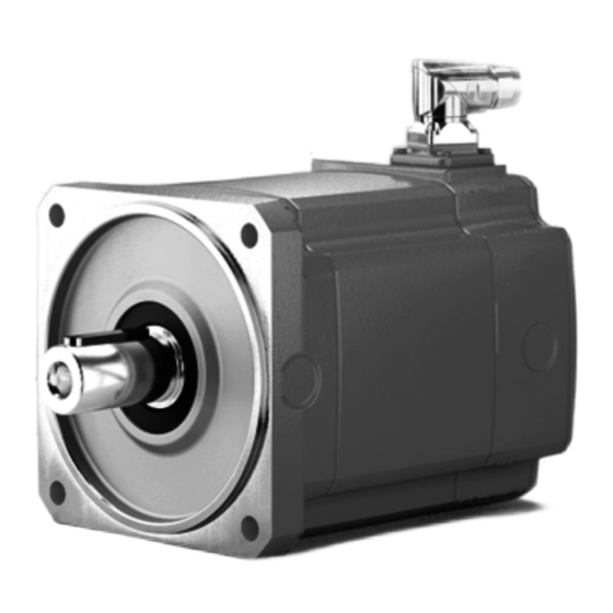
Page 14: Motor Structure
Structure of the motor without brake The following figure shows an overview of the motor components: 28956583947 [1] Output shaft with key [4] Housing [2] Flange [5] Power plug connector [3] Eyebolt [6] Signal plug connector Operating Instructions – CM3C63 – 100... -
Page 15: Nameplate And Type Designation
• Mass • Maximum permitted current • Ambient temperature • Thermal class • System voltage, voltage of the supplying inverter • Nominal braking torque • TENV (Totally Enclosed Non-Ventilated) • Mounting location (plant code) Operating Instructions – CM3C63 – 100... - Page 16 UR mark to confirm that UL (Underwriters Laboratory) is informed about the registered components; register number by UL: E337323 CSA mark to confirm the market conformity of the Canadian Standard As- sociation (CSA). Operating Instructions – CM3C63 – 100...
- Page 17 3.2.3 Type designation This table shows an example type designation: CM3C80L-60A-K/PK/RH1M/SMB CM3C Product family Size and length of the motor Rated speed and system voltage Shaft design Temperature sensor /RH1M Encoder /SMB Plug connector Operating Instructions – CM3C63 – 100...
-
Page 18: Drive Designs And Options
/BZ..D for operation on direct DC voltage supply Manual brake release of BZ.., BZ..D, and BZ..Z brake Automatic re-engaging 1) Optionally available as safety brake. 3.3.3 Temperature sensor/temperature detection Designation Option Pt1000 temperature sensor Operating Instructions – CM3C63 – 100... - Page 19 High Class 1), 2) ® /AK0J Multi-turn encoder, HIPERFACE High Class 1), 2) /AH1Q Multi-turn encoder, DRIVE-CLiQ High Class 1) Optionally available as safety encoder. 2) Available on request. 3.3.5 Designation Option Forced cooling fan Operating Instructions – CM3C63 – 100...
-
Page 20: Functional Safety
In the addendum to the operating instructions "Safety encoders and safety brakes for synchronous servomotors CMP, CMPZ, and CM3C.." the characteristic safety values for determining the safety level of systems and machines are specified in chapter "Characteristic safety values". Operating Instructions – CM3C63 – 100... -
Page 21: Mechanical Installation
Make sure that the drive is designed according to the ambient condi- tions. Functional safety If the drive has the FS logo on the nameplate, observe the information on mechanical installation in the corresponding addendum to the operating instructions. Operating Instructions – CM3C63 – 100... -
Page 22: Motor Installation Notes
Make sure that the customer's counter-bearing is unobstructed and can move freely. • Ensure that the cooling air supply to the motor is unobstructed. • Make sure that no warm exhaust air from other devices is drawn in. Operating Instructions – CM3C63 – 100... -
Page 23: Installation Tolerances
Motor mounting to MD adapter The following note only applies to motors in compact mounting with the MD adapter. These motors have the identification letter "D" for the shaft design in their type desig- nation (e.g. CM3C71M-30A-D/PK/RH1M/SMB). Operating Instructions – CM3C63 – 100... - Page 24 Gear units with the MD adapter may only be operated with CM3C.. servomotors with shaft design D. On CM3C.. servomotors, a label is attached that indicates that CM3C.. servomotors with MD adapter must never be operated without a gear unit. 40191921291 Operating Instructions – CM3C63 – 100...
-
Page 25: Electrical Installation
Severe or fatal injuries. • Do not touch the male contacts in the power plug connector. • Install a touch guard at the power plug connector if no mating connector is plugged in. Operating Instructions – CM3C63 – 100... -
Page 26: Additional Regulations
Observe the operating instructions of the frequency inverter. Additional regulations The generally applicable installation regulations for low-voltage electric equipment (such as DIN IEC 60364, DIN EN 50110) must be complied with when setting up elec- trical machinery. Operating Instructions – CM3C63 – 100... -
Page 27: Wiring Notes
3. If you have any questions regarding the handling of the control input, contact SEW‑EURODRIVE. Operating Instructions – CM3C63 – 100... -
Page 28: Connecting The Motor And The Encoder System Via Plug Connector Sm./Sb./Sh
As standard, the electric motors are supplied with the SM./SB. plug connector system in two-cable technology. In the basic version, SEW-EURODRIVE delivers electric motors with a connector on the motor end and without mating connector. The encoder system is connected using a separate 12-pin round plug connector (M23). - Page 29 M: Motor B: Brakemotor H: Hybrid design (power rating and signals) 1: Connector size 1 (1.5 – 4 mm B: Connector size 1.5 (6 – 16 mm C: Connector size Cross section 1: 1.5 mm 2: 2.5 mm 4: 4 mm 6: 6 mm 10: 10 mm 16: 16 mm 25: 25 mm 35: 35 mm Operating Instructions – CM3C63 – 100...
-
Page 30: Connecting The Two-Cable Technology
"Radial" connector position The different plug connectors of the individual motor sizes are available in the follow- ing designs: Plug connector Connector position SM1/SB1 SMB/SBB Radial Adjustable Steplessly adjustable positions Available – Not available Operating Instructions – CM3C63 – 100... - Page 31 Brake 15 Protective earth Protective earth Protective earth Motor phase U Motor phase U Motor phase U Motor phase W Motor phase W Motor phase W Motor phase V Motor phase V Motor phase V Operating Instructions – CM3C63 – 100...
- Page 32 SEW‑EURODRIVE. BK (3) GNYE GNYE BK (1) BK (2) 9007228536929291 BZ../BZ..D brake (optional) Connection to rectifier from SEW‑EURODRIVE in accordance with operating instructions. For BZ..D, there is no port 14 (contact B). Operating Instructions – CM3C63 – 100...
- Page 33 Connect the shield to the metal housing of the connector. The color code corresponds to the cables from SEW‑EURODRIVE. BK (1) BK (3) GNYE GNYE 29282190731 BK.. brake (optional) Connection to SEW rectifier according to operating instructions. Operating Instructions – CM3C63 – 100...
- Page 34 SEW‑EURODRIVE. BK (1) BK (3) BK (2) GNYE GNYE 29282193163 BZ../BZ..D brake (optional) Connection to rectifier from SEW‑EURODRIVE according to operating instructions. For BZ..D, there is no port 14 (contact 1). Operating Instructions – CM3C63 – 100...
- Page 35 CMP.. and CM3C motors. Due to the installation design, the color coding of the cores might vary. Pin assignment BNVT RDWH R1 (reference +) BKWH R2 (reference -) WHBK S4 (sine -) S1 (cosine +) S3 (cosine -) S2 (sine +) 18014427791655691 Operating Instructions – CM3C63 – 100...
- Page 36 Pin assignment of the brake control with /BK.. or /BZ..D brake BMV brake controller DC 24 V DC 24 V 9007212241295115 Connection 1, 2 Power supply Connection 3, 4 Signal (inverter) Braking contactor BS or BZ.D 24 V 12986690059 Operating Instructions – CM3C63 – 100...
- Page 37 The brake must be protected against overvoltages in the following cases, e.g. by means of a varistor protection circuit: • for operation with third-party inverters, • for brakes that are not supplied directly from inverters from SEW-EURODRIVE. Operating Instructions – CM3C63 – 100...
- Page 38 Cut-off in the DC and AC circuits / rapid application of the brake with SB1, SBB when using a BZ.. brake BMP brake rectifier when using a BZ.. brake Cut-off in the DC and AC circuits / rapid application of the brake / integrated voltage relay with SBB. Operating Instructions – CM3C63 – 100...
- Page 39 Cut-off in the DC and AC circuits / rapid application of the brake / integrated voltage relay / DC 24 V control input integrated with SBB. 24 V 24 V 9007202156720139 Connection 1, 2 Power supply Connection 3, 4 Signal (inverter) Operating Instructions – CM3C63 – 100...
- Page 40 Cut-off in the DC and AC circuits / rapid application of the brake / DC 24 V control in- put integrated with SBB. 24 V 24 V 24 V 24 V 2901984523 Connection 1, 2 Power supply Connection 3, 4 Signal (inverter) Operating Instructions – CM3C63 – 100...
- Page 41 Electrical installation Connecting the two-cable technology BSG brake control unit when using BZ.. brake For DC 24 V supply with SBB. 24 V 24 V 2901987211 Operating Instructions – CM3C63 – 100...
-
Page 42: Connecting Single-Cable Technology
The right-angle SD1/SDB plug connectors can be rotated to achieve the required posi- tions: 18014430805019019 5.7.1 8790995467 [A] View A [B] View B [C] Customer connector with socket contacts [D] Flange socket with pin contacts installed at the factory Operating Instructions – CM3C63 – 100... - Page 43 The pin assignment of the plug connector depicts the contact end of the connections. Function Motor connection for motors in encoderless design Connection type M23, male, male thread, TE Connectivity – Intercontec products, series 723, SEW-EURODRIVE insert, SpeedTec equipment, coding ring: without, protected against contact Pin assignment 34609095051...
- Page 44 The pin assignment of the plug connector depicts the contact end of the connections. Function Motor connection for motors in encoderless design Connection type M40, male, male thread, TE Connectivity – Intercontec products, series 740, SEW-EURODRIVE insert, SpeedTec equipment, coding ring: without, protected against contact Pin assignment Motor assignment...
- Page 45 EMC interference suppression of the 24 V supply. For brakes with external DC supply of more than 24 V and without BMV, a 300 V varistor must be used. Operating Instructions – CM3C63 – 100...
- Page 46 DBØØ modular NOTICE Damage to the BK../BZ..D brake. Possible damage to property. • It is essential that you observe the correct polarity of the BK../BZ..D brake supply. Check the polarity when replacing the brake. Operating Instructions – CM3C63 – 100...
- Page 47 Cut-off in the DC and AC circuits / rapid application of the brake with SH1, SHB. SHB [A] BMP brake rectifier Cut-off in the DC and AC circuits / rapid application of the brake / integrated voltage relay with SH1 and SHB. SHB [A] Operating Instructions – CM3C63 – 100...
- Page 48 / DC 24 V control input integrated / LED ready for operation display with SH1 and SHB. BMKB BMKB 24 V 24 V 34756329995 Connection 1, 2 Power supply Connection 3, 4 Signal (inverter) Operating Instructions – CM3C63 – 100...
- Page 49 Cut-off in the DC and AC circuits / rapid application of the brake / DC 24 V control in- put integrated with SH1, SHB. 24 V 24 V 24 V 24 V 34756352523 Connection 1, 2 Power supply Connection 3, 4 Signal (inverter) Operating Instructions – CM3C63 – 100...
-
Page 50: Connection With Terminal Box
® or individual signal cables (e.g. with MOVILINK DDI) must be insulated by the cable jacket or insulating tubing up to the connection to the terminal strip. Please ensure that the insulation cannot slip. Operating Instructions – CM3C63 – 100... - Page 51 R, B, L and T are rotated accordingly. 270° 0° 180° 90° 32761029643 The cable entry position is specified with X, 1, 2, 3. As standard, the terminal box is delivered in 270° design with cable entry "X". 9007228568864651 Operating Instructions – CM3C63 – 100...
- Page 52 Electrical installation Connection with terminal box As depicted below, only terminal box position "X" is available for motor size CM3C63. Cable entry is possible from 3 sides. 9007228568088587 Observe that the terminal box position is defined when ordering the motor. The termi- nal box must not be turned afterwards.
- Page 53 Electrical installation Connection with terminal box 5.8.3 Terminal assignment of terminal box KK CM3C63 9007229916482315 Terminal [1] Connection Line phase U Line phase V Supply system Line phase W Protective earth Brake control connection Terminal [2] BMV.. BS24 BME.., BMP.., BMH.., BMK.., BST.., SBM..
- Page 54 Motor protection Motor protection The connection diagram and signal logics of the RH1M resolver are identical for CMP.. and CM3C.. motors. Due to the installation design, the color coding of the cores might vary. Operating Instructions – CM3C63 – 100...
- Page 55 If the system complies with the specifications for direct brake control, then a BK.. brake can also be controlled directly via the brake output of a servo inverter by SEW‑EURODRIVE. BMV brake control unit – CM3C63 24 V 24 V...
- Page 56 Pin assignment of the brake control with BZ.. brake BME.. brake rectifier Cut-off in the AC circuit / normal application of the brake. 2901990923 Cut-off in the DC and AC circuit / quick application of the brake. 2901992587 Operating Instructions – CM3C63 – 100...
- Page 57 Electrical installation Connection with terminal box BMP.. brake rectifier Cut-off in the DC and AC circuits / rapid application of the brake / integrated voltage relay. 2901995275 Operating Instructions – CM3C63 – 100...
- Page 58 Electrical installation Connection with terminal box BMH.. brake rectifier Cut-off in the AC circuit / normal application of the brake. 2901997963 Cut-off in the DC and AC circuit / quick application of the brake. 2901999627 Operating Instructions – CM3C63 – 100...
- Page 59 Cut-off in the DC and AC circuits / rapid application of the brake / integrated voltage relay. 24 V 2902002315 Connection 1, 2 Power supply Connection 3, 4 Signal (inverter) BSG.. brake control unit For DC voltage supply with DC 24 V. 24 V 2902005003 Operating Instructions – CM3C63 – 100...
- Page 60 ≤ 16 mm Design 3 Ring cable lug Small connection ac- cessories enclosed in 6.0 Nm ≤ 25 mm Design 3 Ring cable lug Premounted connection pieces 10.0 Nm ≤ 50 mm Design 3 Ring cable lug Premounted connection pieces Operating Instructions – CM3C63 – 100...
-
Page 61: Prefabricated Cables For Two-Cable Technology
Part number of the cable SEW‑EURODRIVE does not offer prefabricated cables for encoders EH0E, AH0E, EH1E and AH1E with EnDat 2.2. Refer to chapter "Technical data of the encoders" for information on the available connectors. Operating Instructions – CM3C63 – 100... - Page 62 Brakemotor cable ../SB.. for /BK and /BZD brakes (→ 2 66) Brakemotor cable ../SB.. for /BZ brakes (→ 2 65) Brakemotor extension cable ../SB.. for /BK, /BZD and /BZ brakes (→ 2 66) For further information on the cables, refer to chapter "Configuring the permitted cable length". Operating Instructions – CM3C63 – 100...
- Page 63 Motor connec- Black U/L1 Not prefabricated tion phase U Green/yellow GNYE – Not prefabricated PE connection Motor connec- Black W/L3 Not prefabricated tion phase W Motor connec- Black V/L2 Not prefabricated tion phase V Operating Instructions – CM3C63 – 100...
- Page 64 – – – – Brake connec- Brake Black BK (1) Not prefabricated tion + Brake connec- – Brake Black BK (3) Not prefabricated tion - Motor connec- Black U/L1 Not prefabricated tion phase U Operating Instructions – CM3C63 – 100...
- Page 65 Motor connec- Black U/L1 Not prefabricated tion phase U Green/yellow GNYE – Not prefabricated PE connection Motor connec- Black W/L3 Not prefabricated tion phase W Motor connec- Black V/L2 Not prefabricated tion phase V Operating Instructions – CM3C63 – 100...
- Page 66 4 × 6 mm + 3 × 1.5 mm – 28125509 brakes SBB / M40 SMB / M40 4 × 10 mm + 3 × 1.5 mm – 28125517 SpeedTec SpeedTec 4 × 16 mm + 3 × 1.5 mm – 28125525 Operating Instructions – CM3C63 – 100...
- Page 67 All prefabricated encoder cables with connectors on the motor side are designed in SpeedTec. ® X15: MOVIDRIVE modular/system/technology basic device The encoders and resolver can be connected only to X15 at the D-Sub --> X.. ® MOVIDRIVE modular/system/technology basic device. X17: CES11A multi-encoder card Operating Instructions – CM3C63 – 100...
- Page 68 Conductor color Contact Signal Conductor color Contact IEC 60757 S1 (COS +) S3 (COS -) Blue S2 (SIN +) Yellow S4 (SIN -) Green Data - Violet Data + Black Gray-pink/pink GYPK/PK Red-blue/gray RDBU/GY Brown White Operating Instructions – CM3C63 – 100...
- Page 69 13356267 RUN ERR RUN ERR 28125665 13356291 28125673 13356305 28125746 CM3C.. /SM.. CM3C.. /SB.. 28125754 /AK0H CM3C.. /KK /AK0H 9007232138205835 All prefabricated encoder cables with connectors on the motor side are designed in SpeedTec. Operating Instructions – CM3C63 – 100...
-
Page 70: Prefabricated Cables For Single-Cable Technology
+ 3 × 1 mm + 18191312 Motor cable/ – 4 × 0.34 mm Open end brakemotor cable 4 × 6 mm + 3 × 1.5 mm + 18191320 – 4 × 0.34 mm SHB / M40 4 × 10 mm + 18191339 SpeedTec 3 × 1.5 mm + – 4 × 0.34 mm Operating Instructions – CM3C63 – 100... - Page 71 Not prefabricated Brake connec- tion + Brake - Black Not prefabricated Brake connec- tion - Yellow/green GNYE – Not prefabricated PE connection White – Not prefabricated Motor protection Blue – Not prefabricated Motor protection Operating Instructions – CM3C63 – 100...
- Page 72 18191371 – 4 × 0.34 mm SHB / M40 SHB / M40 4 × 10 mm + 18191398 SpeedTec SpeedTec 3 × 1.5 mm + – 4 × 0.34 mm For further information on the cables, refer to chapter "Configuring the permitted cable length". Operating Instructions – CM3C63 – 100...
-
Page 73: Assembling The Cables
Cable crimping diameter signal mating con- nector SpeedTec 16447115 0.14 – 1 6 – 10 The complete connector service pack always includes the following parts: • Feedback connector • Insulation inserts • Socket contacts Operating Instructions – CM3C63 – 100... -
Page 74: Options
Motor overheating due to inadequate thermal motor protection. Motor damage • In addition to a temperature sensor activate a current monitoring device (I t, rms current monitoring) and a motor model for thermal protection, as installed in servo systems by SEW‑EURODRIVE. Operating Instructions – CM3C63 – 100... - Page 75 The temperature sensor is unipolar which means that interchanging the incoming cables does not change the measurement result. Typical characteristic curve of Pt1000 2000 1800 1600 1400 1200 R / Ω 1000 T / °C 9007216765187979 Operating Instructions – CM3C63 – 100...
- Page 76 [1] Shield connected to the metal housing of the connector. Color code according to SEW‑EURODRIVE cable [2] PK (RD/BK) Pin assignment of the plug connector lower part [B] Contact Color code Connection – – – – S1 (cosine +) Operating Instructions – CM3C63 – 100...
- Page 77 Connections CMP50 and CMP63 2900869771 Assignment Connection Core identification (BK/WH) Black with white lettering U, V, W Power Protective earth (GN/YE) Green/yellow Assignment Core identification Brake control connection (YE) Yellow (RD) Red Brake (YE) Yellow (BU) Blue Operating Instructions – CM3C63 – 100...
- Page 78 Reference sin + Sine DATA sin - DATA – – Ground – – Supply voltage PK+/TF PK+/TF Motor protection Motor protection PK-/TF PK-/TF Terminal assignment of terminal box KKS CMP71 – CMP112 [PE] 40862798731 Operating Instructions – CM3C63 – 100...
- Page 79 1 g. Electrical connection CAUTION Starting up the fan when it is not installed. Risk of injury due to rotating parts. • The fan may only be taken into operation after installation. Operating Instructions – CM3C63 – 100...
- Page 80 The VR forced cooling fan is only available for DC 24 V voltage. • DC 24 V ± 20% • Plug connector connection • Maximum connection cross section 2 × 1 mm • Cable gland Pg7 with inner diameter 7 mm DC 24 V 2903419147 Connector contact Connection 24 V + Operating Instructions – CM3C63 – 100...
-
Page 81: Startup
If you have a pacemaker or any other active medical implant, keep a distance > 500 mm between the body part with the active medical implant and the motor. • Inform people with active medical implants about the dangers. Operating Instructions – CM3C63 – 100... - Page 82 Only operate the brake as holding brake. • The brake may only be applied when the speed is ≤ 20 min . For greater speeds, contact SEW‑EURODRIVE. • Emergency stops from higher motor speeds are permitted. Operating Instructions – CM3C63 – 100...
-
Page 83: Before Startup
INFORMATION If the insulation resistance is too low, the motor has absorbed moisture. SEW‑EURODRIVE recommends to send the motor back to SEW‑EURODRIVE to- gether with a description of the fault. Operating Instructions – CM3C63 – 100... - Page 84 Startup Startup after storage The following figure shows the minimum insulation resistance depending on the tem- perature. R/MΩ T/°C 9007202147046283 Resistance temperature point (RT point) Operating Instructions – CM3C63 – 100...
-
Page 85: Inspection/Maintenance
Otherwise, the warranty will become void. CAUTION The surfaces on the drive can be very hot during operation. Risk of burns. • Let the motor cool down sufficiently before you start working on it. Operating Instructions – CM3C63 – 100... -
Page 86: Maintenance Intervals
High mass moments of inertia due to the motion of the drive, e.g. in mobile drives or drives subject to high impact and vibration load • Application-related generative torques or torsional vibrations • External environmental factors, such as moisture, high degree of UV exposure, low ambient temperatures, etc. Operating Instructions – CM3C63 – 100... -
Page 87: Notes On The Bk
If the working air gap exceeds the maximum permitted value, the brake lining carrier or the brake must be replaced by SEW‑EURODRIVE or another qualified workshop. Operating Instructions – CM3C63 – 100... - Page 88 7. Loosen the cap screws [1052] 8. Carefully remove the entire magnet body [54] together with the pressure plate [49] - pay attention to the brake cable! 9. Remove the brake lining carrier [5] Operating Instructions – CM3C63 – 100...
- Page 89 Forced cooling fan [28] Closing caps Encoder/resolver [49] Pressure plate Plug connector [50/265] Brake springs Terminal box [54] Magnet body Retaining screws of the pressure plate [304] Cover Manual brake release [1052] Cap screw Operating Instructions – CM3C63 – 100...
- Page 90 Installation, graphic in chapter "Retrofitting manual brake release" 16. No manual brake release available: • Attach the closing caps [28] 17. Calibrate the encoder or resolver [2] 18. Mount cover [304] 19. If present, install the forced cooling fan [1]. Operating Instructions – CM3C63 – 100...
- Page 91 Installation, graphic in chapter "Retrofitting manual brake release" 13. No manual brake release available: • Attach the closing caps [28] 14. Calibrate the encoder or resolver [2] 15. Mount cover [304] 16. If present, install the forced cooling fan [1] Operating Instructions – CM3C63 – 100...
- Page 92 Measuring the working air gap for brakes without manual brake release WARNING! Risk of injury! De-energize the motor and brake and safeguard the drive against unintentional power-up. 2. If installed, remove the forced cooling fan. 3. Remove the signal connector. Operating Instructions – CM3C63 – 100...
- Page 93 9. Remove the studs from the holes of the manual brake release [3]. 10. Important! Check the Litz wires [1] [2] for possible damages. 11. Important! Check of the encoder connector is correctly inserted into the encoder [4]. Operating Instructions – CM3C63 – 100...
- Page 94 The working air gap cannot be adjusted. 8. Remove the studs from the holes of the manual brake release [3]. 9. Install the encoder cover. Tighten the screws with a tightening torque of 6.8 Nm. Operating Instructions – CM3C63 – 100...
-
Page 95: Cleaning
Clean the servomotor regularly, depending on the operating and ambient conditions. Connection cable Check the connection cable for damage at regular intervals. Replace if necessary. Operating Instructions – CM3C63 – 100... -
Page 96: Technical Data
CM3C80 CM3C100 Brake Static braking torque 4,100°C Dynamic braking torque 10.7 23.8 23.8 33.6 Nominal brake voltage (rating range) DC V 24 (21.6 – 26.4) Nominal holding current DC A 0.80 0.94 0.94 Operating Instructions – CM3C63 – 100... - Page 97 Nominal power brake coil in W 19.2 22.5 22.5 Coil resistance R at 20 °C in Ω = 24 (21.6 – 26.4) VDC Minimum static braking torque (holding torque) at 100 °C 4, 100 °C Coil resistance at 20 °C Nominal voltage (rated voltage range) Operating Instructions – CM3C63 – 100...
-
Page 98: Technical Data For The Bz
Nominal DC brake voltage Nominal DC holding current I (Rating range) (21.6 – 26.4) 0.92 1.15 1) The brake voltage DC 24 V requires a high current and is possible only with a limited cable length. Operating Instructions – CM3C63 – 100... - Page 99 Permitted braking work per braking in 5.35 10.2 per,N case of emergency stop Permitted braking work until 43000 46000 insp maintenance Permitted mechanical speed 7200 5400 max,0 Permitted brake application speed in 6000 4500 max,1 case of emergency stop Operating Instructions – CM3C63 – 100...
- Page 100 – – (380 – 431) – – – (432 – 484) – 1263 – 1171 – (484 – 542) Accelerator coil resistance at 20 °C Coil section resistance at 20 °C Nominal voltage (rated voltage range) Operating Instructions – CM3C63 – 100...
- Page 101 The values are based on the assumption that you operate the lever at the up- per end. 4810849419 Brake Motor Actuating force F BZ05, BZ05D CM3C63 BZ1, BZ1D CM3C71 BZ3, BZ3D CM3C80 BZ5, BZ5D CM3C100 Operating Instructions – CM3C63 – 100...
-
Page 102: Characteristic Safety Values Of Bk.. Brakes
BZ3, BZ3D 12 × 10 BZ5, BZ5D 9 × 10 SEW‑EURODRIVE offers BZ.. brakes also as safety brakes. For more information, consult the addendum to the operating instructions "Safety encoders and safety brakes – CM3C.. servomotors – Functional safety". Operating Instructions – CM3C63 – 100... -
Page 103: Malfunctions
Motor is buzzing and Drive blocked. Check drive. has high current con- Brake does not release. See chapter "Brake malfunctions" (→ 2 104). sumption Malfunction on the encoder cable Check the encoder cable. Inverter set incorrectly. Check the inverter. Operating Instructions – CM3C63 – 100... -
Page 104: Brake Malfunctions
Brake parameters set incorrectly in the Check brake release and application times. near the brake inverter. Brake does not ap- Maximum permitted working air gap ex- Contact SEW-EURODRIVE. ceeded because brake lining worn Motor/brake replacement by down. SEW‑EURODRIVE. Operating Instructions – CM3C63 – 100... -
Page 105: Encoder Malfunctions
Noise/squeaking Brake parameters set incorrectly in the Check brake release and application times. near the brake inverter. Encoder malfunctions Faults on the encoder are output on the inverter with an appropriate error message. Operating Instructions – CM3C63 – 100... - Page 106 For more information on errors and maintenance, refer to the document "Built-In En- coders and Add-On Encoders, DR.., DRN.., DRU.., EDR.., EDRN.. AC Motors – Inte- grated, Cone Shaft, Spread Shaft, Plug-In Shaft, Hollow Shaft, Encoder Mounting Ad- apters". Operating Instructions – CM3C63 – 100...
-
Page 107: Service
Information on the nameplate (e.g. type designation, serial number, part number, product key, purchase order number) • Brief description of the application • Fault message on the status display • Type of fault • Accompanying circumstances • Unusual events preceding the problems Operating Instructions – CM3C63 – 100... - Page 108 WEEE Directive. Dispose of the product and its accessories according to the national regulations of your country. For further information, contact the responsible SEW‑EURODRIVE branch or an au- thorized partner of SEW‑EURODRIVE. Operating Instructions – CM3C63 – 100...
- Page 112 SEW-EURODRIVE—Driving the world SEW-EURODRIVE GmbH & Co KG Ernst-Blickle-Str. 42 76646 BRUCHSAL GERMANY Tel. +49 7251 75-0 Fax +49 7251 75-1970 sew@sew-eurodrive.com www.sew-eurodrive.com...
Need help?
Do you have a question about the CM3C63 and is the answer not in the manual?
Questions and answers